Main malfunctions and features of replacing fuel pipes in a Chevrolet Niva
The engine power system ensures an uninterrupted supply of fuel from the gas tank to the running car engine. One of the elements of the supply system is fuel pipes, flexible hoses, fuel supply and removal lines, as well as main fuel pipes.
Replacing fuel pipes on a Chevrolet Niva is not the easiest task. While replacing flexible hoses is quite simple, repairing or replacing steel tubes is a labor-intensive process. It is complicated by limited access - work can be carried out under the bottom of the car, so replacement may require a lift or inspection hole. An additional complication is that the fuel supply system is always under pressure, so before carrying out work it is necessary to remove all gasoline from the system.
The power supply system includes elements of the following systems:
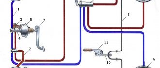
– a fuel supply system, including a fuel tank 4 (Fig. 1), an electric fuel pump 2, pipelines 5, 6 and 13, hoses 12, a fuel rail 8 with injectors 7 and a fuel pressure regulator 9, as well as a fuel filter 11;
Rice. 1. Fuel supply system
– air supply system, including air filter 1 (Fig. 2), air supply pipe 2, throttle assembly 3;
– a fuel vapor recovery system, which includes an adsorber 4 and connecting pipelines.
A fundamental feature of the VAZ-2123 engine power system is the absence of a carburetor, which combines the functions of mixture formation and dosing of the air-fuel mixture into the engine cylinders.
In the distributed injection system installed on this engine, these functions are separated
– the injectors carry out dosed injection of fuel into the intake pipe, and the supply of air required at each moment of engine operation is carried out by a system consisting of a throttle unit and an idle speed regulator.
The fuel injection system and ignition system are controlled by an electronic engine control unit, which continuously monitors, using appropriate sensors, the amount of engine load, vehicle speed, thermal state of the engine, and the optimal combustion process in the engine cylinders.
This control method makes it possible to ensure the optimal composition of the combustible mixture at each specific moment of engine operation, which allows you to obtain maximum power with the lowest possible fuel consumption and low exhaust gas toxicity.
The power supply system is an integral part of the engine control system.
Rice. 2. Location of power system elements in the engine compartment of a car up to 2009
Figure 3: Location of elements of the fuel system of a car produced after 2009
Fuel tank 4 - (see Fig. 1) welded, stamped, secured in the luggage compartment with bolts and nuts. An electric fuel pump is installed at the top of the fuel tank, combined with a fuel level sensor.
From the pump, fuel is supplied to the fuel filter installed in the engine compartment (on later models it is installed on the bottom), and from there it enters the engine fuel rail, mounted on the engine intake pipe.
From the fuel rail, fuel is injected by injectors into the intake pipe.
Excess fuel is drained into the fuel tank through a fuel pressure regulator mounted at the rear end of the fuel rail.
Fuel pump 2 – electrically driven, two-stage, rotary type, installed in the fuel tank, which reduces the possibility of vapor locks forming, since fuel is supplied under pressure and not under vacuum. It supplies fuel at a pressure of more than 284 kPa.
Fuel filter 11 is built into the supply line between the electric fuel pump and the fuel rail and is installed in the engine compartment on the front panel of the body.
Since 2009, the fuel filter has been installed on the bottom of the car closer to the right rear arch and covered with a plastic protective cover.
The filter is non-separable, has a steel body with a paper filter element.
The 8 injector ramp is a hollow bar with injectors and a fuel pressure regulator installed on it.
The injector ramp is fixed to the intake pipe. At the rear end of the ramp there is a valve for controlling fuel pressure, closed with a screw plug.
Injectors 7 are attached to the ramp from which fuel is supplied to them, and with their nozzles they enter the holes of the inlet pipe.
In the openings of the ramp and inlet pipe, the injectors are sealed with rubber O-rings.
The injector is an electromechanical valve in which the shut-off valve needle is pressed against the seat by a spring.
When an electrical impulse is applied from the control unit to the electromagnet winding, the needle rises and opens the nozzle hole, through which fuel is supplied to the engine inlet pipe. The amount of fuel injected by the injector depends on the duration of the electrical pulse.
Fuel pressure regulator 9 - installed on the fuel rail and is designed to maintain a constant pressure difference between the air pressure in the intake pipe and the fuel pressure in the rail.
Rice. 3. Fuel pressure regulator
The regulator consists of valve 5 (Fig. 3) with diaphragm 4, pressed by a spring to the seat in the regulator body. When the engine is running, the regulator maintains the pressure in the injector rail in the range of 284–325 kPa.
The regulator diaphragm is affected by fuel pressure on one side, and pressure (vacuum) in the intake pipe on the other.
When the pressure in the intake pipe decreases (the throttle valve closes), the regulator valve opens at lower fuel pressure, allowing excess fuel to flow through the return line back into the tank.
The fuel pressure in the rail decreases. As the pressure in the intake pipe increases (when the throttle valve opens), the regulator valve opens at a higher fuel pressure and the fuel pressure in the rail increases.
Air filter 1 - (see Fig. 2) is installed in the front part of the engine compartment on rubber supports. The filter element is paper, flat, with a large filter surface area.
The filter is connected to the throttle assembly by a corrugated air supply pipe, consisting of two parts.
A mass air flow sensor is installed between the pipe and the filter.
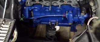
Throttle assembly 3 - (Fig. 5) is fixed to the receiver. It controls the amount of air entering the intake pipe.
The flow of air into the engine is controlled by a throttle valve connected to the accelerator pedal drive. The throttle pipe includes throttle position sensor 4 (Fig. 5) and idle speed regulator 5.
In the flow part of the throttle pipe (in front of the throttle valve and behind it) there are vacuum sampling holes necessary for the operation of the crankcase ventilation system and the adsorber of the gasoline vapor recovery system.
Rice. 5. Throttle assembly
Idle speed regulator 5 - (see Fig. 5) regulates the crankshaft speed during idle mode, controlling the amount of air supplied bypassing the closed throttle valve.
It consists of a two-pole stepper motor and a cone valve connected to it.
The valve extends or retracts based on signals from the controller.
When the regulator needle is fully extended (which corresponds to 0 steps), the valve completely blocks the air passage.
When the needle moves in, an air flow is provided that is proportional to the number of steps the needle moves away from the seat.
Adsorber for fuel vapor recovery system: 1 – adsorber; 2 – solenoid valve for purge of the adsorber; 3 – connecting hoses.
The fuel vapor recovery system uses the method of vapor absorption by carbon adsorber 4 (see Fig. 6).
It is installed in the engine compartment and connected by pipelines to the fuel tank and throttle pipe.
On the canister cover there is a solenoid valve for purge the canister (on new models, the canister purge valve is installed on the rear of the receiver), which switches the operating modes of the system based on signals from the engine control unit.
When the engine is not running, the solenoid valve is closed and gasoline vapors from the fuel tank flow through the pipeline to the adsorber, where they are absorbed by granular activated carbon.
When the engine is running, the adsorber is purged with air and the vapors are sucked off to the throttle body and then into the intake pipe for combustion during the operating process.
The controller controls the purge of the adsorber, including the solenoid valve located on the adsorber cover.
When voltage is applied to the valve, it opens, releasing vapor into the intake pipe. The valve is controlled using the pulse width modulation method.
The valve turns on and off at a frequency of 16 times per second (16 Hz). The higher the air flow, the longer the duration of the valve activation pulses.
The controller turns on the canister purge valve when all of the following conditions are met:
– coolant temperature above 75 °C;
– vehicle speed exceeds 10 km/h.
Once the valve is turned on, the speed criterion changes. The valve will only turn off when the speed decreases to 7 km/h;
– throttle opening exceeds 4%. This factor does not matter in the future if it does not exceed 99%.
When the throttle valve is fully opened, the controller turns off the canister purge valve.
Malfunctions of the fuel vapor recovery system lead to unstable idling, engine stalling, increased toxicity of exhaust gases and deterioration of the vehicle's driving characteristics.
The following system malfunctions are possible:
– malfunction of the purge solenoid valve;
– damage to the adsorber;
– overflow of the adsorber, which takes up more than 60 g of fuel (the weight of the new adsorber is no more than 1.1 kg);
– Damaged or incorrectly connected hoses.
Design and principle of operation
The Chevrolet Niva fuel system consists of several elements, which include fuel lines of various devices and purposes:
- metal pipe for supplying gasoline to the fuel rail;
- steel pipe for discharging gasoline from the ramp;
- flexible high pressure hoses connected to the fuel filter;
- steel pipelines coming from the gas tank and located under the bottom of the car.
Steel pipelines extend from the fuel tank and are responsible for the supply and removal of gasoline. The gasoline supply pipe is connected to the fuel filter using a flexible rubberized or nylon hose. Gasoline passes through a fuel filter, which cleans gasoline from foreign impurities. On the other side of the filter comes another rubberized hose that connects to the fuel supply pipeline to the ramp.
If excess gasoline enters the ramp, it is removed from it through a steel fuel outlet pipe. Its end is connected to a flexible hose that leads to a fuel line for returning gasoline back to the gas tank. In this way, excess gasoline not used by the engine is returned to the gas tank.
Operating principle of RTD
The valve design and operating principle depend on the type of fuel system of a particular vehicle. There are 3 ways to supply gasoline from the tank to the injectors:
- The pump together with the regulator is installed inside the tank; fuel is supplied to the engine through one line.
- Gasoline is supplied through one tube and returned through another. The fuel system check valve is located on the distribution rail.
- The circuit without a mechanical regulator provides for electronic control of the fuel pump directly. The system contains a special sensor that registers pressure; the pump performance is regulated by the controller.
Symptoms of a problem
Understanding that fuel pipes need replacing is quite simple. If, when examining the underbody of the car, it is clear that the metal tubes are rusted, then they need to be replaced. Damage to the highways is also indicated by gasoline leaks remaining at the parking lot. Another sign of a malfunction is the smell of gasoline in the car interior.
The pipelines of the gasoline supply system to the engine cylinders may have various malfunctions.
- The most common failure is loosening or destruction of the O-rings at the joints of hoses and pipelines. O-rings are classic consumables, so they quickly fail.
- The integrity of the fasteners themselves may also be compromised. In this case, a violation of the connection leads to a gasoline leak.
- Rubber or nylon hoses last for several years. A hose rupture also compromises the integrity of the system.
- Steel fuel supply pipes can last for many years. Their main enemy is rust - under its influence, leaks can form in pipelines.
The reasons for wear of the connecting elements of the fuel system are the effects of rust (relevant for main gas pipelines), chemical or physical effects, or simple wear.
Gasoline vapor recovery system
Gasoline vapor recovery system
Valve operation mode
| a. Filler plug B. Control valve C. Thermal pneumatic valve | d. Absorber tank e. Channel R |
| Temperature | Increased vacuum in the tank | There is high pressure in the tank | Above 54°C | Below 35°C | ||
| Thermo-pneumatic valve condition | – | – | Open | Closed | ||
| Throttle position | – | – | The flap connects channel P to the intake manifold | The flap closes channel P | – | |
| Tank control valves | 1 | Closed | Open | – | – | – |
| 2 | Open | Closed | – | – | – | |
| 3 | Open | Closed | – | – | – | |
| Filler neck check valve | – | – | – | – | – | |
| Gasoline vapor removal mode | Purge the fuel tank | Vapors from the tank are absorbed in the tank | Vapors from the tank with the absorber are directed to the intake manifold | Vapors from the tank are absorbed in the tank |
This system is designed to capture gasoline vapors in the fuel tank, throttle body and intake manifold, thereby preventing them from escaping into the atmosphere as hydrocarbons. The system consists of a tank with an absorber (activated carbon), pipelines connecting the absorber to the fuel tank, a thermal pneumatic valve and a control valve. When the engine is not running, gasoline vapors enter the absorber from the tank and throttle chamber, where they are absorbed. When the engine starts, the tank with the absorber is purged with a flow of air sucked in by the engine, the vapors are carried away by this flow and are burned in the combustion chamber. The tank is equipped with three ball valves assembled in a single housing. Depending on the operating mode of the engine and the pressure in the fuel tank, ball valves connect or disconnect the tank with a thermopneumatic valve (which is connected in series with the throttle valve chamber). Examination
| EXECUTION ORDER |
| 1. Malfunctions in the system such as failure of the control valve, damage to the absorber tank, delamination or cracking of hoses, or incorrect connection of hoses lead to unstable idling and deterioration of engine traction qualities. Check the condition of the tank filler plug gasket (see subsection 5.7). |
| 2. An obvious loss of gasoline or the smell of gasoline in the cabin can be caused by leaking gasoline lines, cracks or other damage to the absorber tank, failure of the control valve, as well as disconnection, improper connection, pinching, chafing, or mechanical damage to the connecting hoses. |
| 3. Check the condition of each hose connected to the tank, examining the entire length of the hose. Replace the hose if necessary. |
| 4. Check for gasoline leaks at the bottom of the tank. If there is a leak, replace the tank and check the condition of the hoses and the correctness of their connections. |
| 5. Inspect the tank. If cracks or mechanical damage are detected, replace the tank. |
| 6. Check the cleanliness of the filter and the serviceability of the control valve. Apply air under slight pressure into the tank vent tube. Air should flow freely from other tubes. Otherwise, replace the tank. |
| 7. Check the operation of the thermal pneumatic valve. With the engine completely cooled, apply air to channel A using a hand pump. The thermopneumatic valve should not allow air to pass through. Warm up the engine to a temperature of at least 55° C. The valve should now allow air to pass through. Otherwise, replace the thermal pneumatic valve. |
Replacing the activated carbon tank
| EXECUTION ORDER |
| 1. Disconnect the hoses from the tank, having previously marked them. |
| 2. Unscrew the fastening bolts, move the tank along with the bracket down, disconnect the hoses from the control valve and remove the tank from the car. |
| 3. Installation is performed in reverse order. |
What elements make sense to repair?
O-rings, clamps and flexible hoses are typical consumables. Their service life is short, and repairs are impractical. Connecting hoses cost within a few hundred rubles, connecting elements are even cheaper, so it is much easier to replace them with new ones.
Steel pipelines are a completely different matter. The Chevrolet Niva user manual states that the damaged part of the fuel line can be repaired. Repairs are made by replacing the damaged area with a reinforced hose. The decision on the feasibility of repair is made based on measuring the length of the damaged section of the gas pipeline.
Features of DIY replacement
Before you begin replacing or repairing fuel lines, you must relieve the pressure in the gasoline supply system to the engine. To do this you will have to perform the following steps.
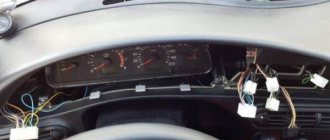
- It is necessary to de-energize the fuel pump, which supplies gasoline to the engine injectors. The fuel pump power relay is located in the passenger compartment on the driver's side. When you remove the front dashboard cover, a block consisting of four relays opens. The fuel pump relay is the third in a row.
- After turning off the fuel pump, you need to “burn” the fuel remaining in the system. To do this, you need to start the engine and leave it running until it stalls due to lack of gasoline.
- For a final check, try to start the engine again by turning the starter for a few seconds.
Then they proceed to dismantling and replacing faulty elements of the fuel system. Before this, you need to de-energize the car by disconnecting the negative terminal of the battery.
Removal of flexible hoses is carried out from the engine compartment.
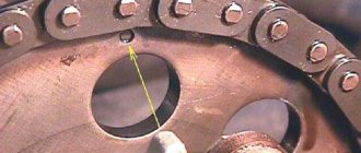
- The location where the hoses are attached to the inlet tube is indicated by a yellow warning mark. You need to remove the hose from the tube by disconnecting the plastic clip and pulling the hose in the opposite direction.
- The second end of the hose is connected to the fuel filter with a fastening nut. You can unscrew it with a 10 key.
- After inspecting the fastening points, they begin installing a new hose. It is attached in a similar way - the end connected to the fuel line is attached to the fixing nut, the other end is attached to the plastic retainer.
In the same way, change the hose connecting the outlet tube and the fuel line of the gas tank.
Replacing metal elements may require the use of a lift or inspection pit. The fuel lines are located underneath the vehicle, so you will need a flashlight to inspect for damage.
Chevrolet Niva fuel system
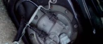
Lifting and turning the Niva VAZ fuel pump module, carefully so as not to damage it, remove the float of the fuel level indicator sensor from the hole in the tank. Having removed the pressure plate from the fuel module cover, we drain the remaining fuel in the module into a previously prepared container.
The connection between the fuel module cover and the tank is sealed with a rubber ring. To prevent objects from falling into the fuel tank, cover its neck with a piece of cardboard. We disassemble the fuel pump on a workbench.
power system Niva Chevrolet • Chevrolet Niva
Using a screwdriver, we remove the mounting bracket for the pressure regulator Niva Chevrolet fuel system. Using pliers, remove the regulator from the module cover socket. Remove the two rubber sealing rings of the regulator. Install the fuel pressure regulator in reverse order. We replace the regulator O-rings with new ones.
Before installing the regulator O-rings, apply a thin layer of engine oil to the O-rings. To replace the fuel level sensor or the Chevy Niva fuel pump, do not remove the fuel pressure regulator. From the Niva Chevrolet fuel system side of the module cover, use a screwdriver to press the fixing plate of the common wire block and disconnect the wire block from the cover connector. By pressing the latch, disconnect the wiring block from the fuel pump.
To remove the fuel level indicator sensor, press out the two sensor clamps and slide the sensor along the housing toward the cover.
Remove the fuel level indicator sensor with wire blocks. Install the fuel level indicator sensor in the reverse order.
When replacing the fuel pump, it is better to remove the fuel level indicator sensor to avoid damage. Use a screwdriver to pry up the drain tube and disconnect it from the module body.
By pressing the four latches of the pump holder, remove the cover of the fuel module assembled with the holder and the fuel pump. Remove the spring from the guide post of the cover. Using a screwdriver, remove the strainer.
The electric fuel pump module should be removed carefully to prevent deformation of the fuel level lever and, as a result, incorrect fuel level readings. Removing the strainer 1. Drain the remaining fuel from the intake chamber of the electric fuel pump module into a specially prepared container. Disconnect the internal block on the cover of the electric fuel pump module by carefully unscrewing the block retainer.
Remove the fuel intake chamber stroke limiter by carefully loosening the ring using a flat-head screwdriver. Disconnect the jet pump from the intake chamber. Disconnect the fasteners of the electric fuel pump mounting bracket.
Niva Chevrolet fuel system Disconnect the chamber and the bracket with the electric fuel pump to provide access to the strainer. The controller controls the operation of the injectors. The injectors are sealed in the ramp and in the intake pipe with rubber rings and fixed to the ramp with metal clips.
At the injector outlet there is a nozzle with four holes through which fuel is injected under pressure. If the injector winding is broken or shorted, it should be replaced.
Chevrolet Niva fuel system. Relay for controlling the fuel supply system to the Chevrolet Niva engine
If the injectors are clogged, they can be washed without dismantling at a special service station. Air is supplied to the engine throttle body through the air intake, air filter, mass air flow sensor and corrugated rubber hoses.
The air filter is installed in the front left part of the engine compartment on three rubber support holders.
https://avtoshkolak.ru/remont/niva-shevrole-toplivnaya-sistema-neispravnosti.html https://inter-foto-press.ru/chevrolet/sistema-podachi-topliva-dvigatelya-shevrole-niva.html
Design and principle of operation
The Chevy Niva power system includes the following elements:
- A fuel tank in which gasoline is stored. Hoses are connected to the tank to remove air and gasoline vapors into the adsorber. To prevent fuel from spilling when the machine rolls over, a gravity valve is installed in the drainage system.
- A fuel pump and a gasoline level sensor are built into the tank. The commutator motor provides sufficient pressure in the system to operate the injectors. The Chevrolet Niva uses a vortex-type submersible pump with an energy consumption of 6 amperes.
- A pressure regulator to which fuel is supplied through a reinforced fuel line.
- Fuel rail and injectors that dose gasoline injection.
- Coarse and fine filters. They are installed after the fuel pump and in each of the injectors.
In addition to the listed elements, the system includes a throttle assembly, which regulates the air supply to the cylinders. An electromagnetic valve is installed between it and the adsorber. It controls the flow of gasoline vapor into the intake manifold.
Two types of fuel pressure regulators
On Chevrolet Niva cars until 2009, the RTD was installed on the fuel rail. A pressure fuel line from a fuel pump was connected to the RTD housing. Excess fuel was returned to the gas tank through the drain pipeline, in common parlance “return”. Also, a vacuum supply tube from the intake manifold was connected to a separate housing pipe.
Cars produced after 2009 are equipped with a fuel module, which contains a coarse fuel filter, a turbine electric fuel pump with a control relay, a fuel level sensor and a fuel pressure regulator. Thus, the modern RTD has turned into a conventional overflow valve, which has simplified its design and increased the reliability of the power system as a whole. The function of determining the required instant amount of fuel was taken over by the ECU unit, summing up the readings of the throttle position and mass air flow sensors and controlling the injectors. In the electronic part of the ECU there has been a transition from a processor (controller) of type “7.0” to “7.9.7”.
Important! Controllers "7.0" and "7.9.7" are not interchangeable.
RTD malfunctions are usually caused by the fact that the spring acting on the valve “sags”; its force gradually decreases as a result of prolonged variable loads. The valve no longer fits so tightly to the seat, as a result, a significant portion of the fuel enters the “return”, the pressure in the ramp decreases even with a short stop of the engine. When you press the throttle pedal, the engine does not have enough fuel, which causes “dips” instead of increasing speed, especially during acceleration and transient conditions.
About malfunctions
Characteristic signs of a faulty RTD:
- Unstable operation of the engine at idle, the engine starts with difficulty and the first minutes after starting it “troubles”;
- Due to the unevenly enriched fuel-air mixture entering the cylinders, the crankshaft speed “floats” at idle;
- The engine “does not pull” and “stalls”, that is, it does not develop its former power and loses throttle response;
- When driving, jerks and twitches are felt, slow reactions to pressing the throttle pedal;
- Fuel consumption increases, the content of CO and CH in the exhaust gases increases.
Basic faults
Problems with fuel supply to the cylinders primarily affect engine performance. This manifests itself as follows:
- The engine does not start or is difficult to start.
- The engine is running unsteadily.
- There are “failures” in operation when pressing the accelerator.
- Power decreases, fuel consumption increases.
- Deposits appear on the spark plugs, preventing spark formation.
- The smell of gasoline appears when driving or parking.
- The Check Engine light is on on the dashboard.
- Traces of gasoline leaks appear on the hoses and other parts of the fuel system.
Advice: many of the listed symptoms occur when the ignition system fails. Therefore, to localize the problem, you need to check not only the fuel supply.
Malfunctions of the Niva Chevrolet injection system
Chevrolet Niva cars use a distributed fuel injection system.
It is called distributed injection because fuel is injected into each cylinder with a separate nozzle. The fuel injection system reduces exhaust emissions while improving driving performance and fuel efficiency of the vehicle. When working with the Chevy Niva injection system, be sure to adhere to the following rules: Before removing any components of the injection control system, disconnect the wire from the “–” terminal of the battery. Do not start the engine if the battery cable terminals are not properly tightened. Never disconnect the battery from the vehicle's on-board power supply while the engine is running. When charging the battery, disconnect it from the vehicle's on-board power supply. Do not allow the electronic control unit (ECU) to heat above 65 °C in operating condition and above 80 °C in non-operating condition (for example, in a drying chamber). It is necessary to remove the ECU from the car if this temperature is exceeded. Do not disconnect or connect the wiring harness connectors from the ECU while the ignition is on. Before performing electric arc welding on a vehicle, disconnect the wires from the battery and the wire connectors from the ECU. Perform all voltage measurements with a digital voltmeter with an internal resistance of at least 10 MΩ. The electronic components used in the injection system are designed for very low voltage, so they can easily be damaged by electrostatic discharge. To prevent damage to the ECU by electrostatic discharge: do not touch the ECU connectors or electronic components on its boards with your hands; When working with the programmable read-only memory (PROM) of the control unit, do not touch the pins of the microcircuit.
Malfunctions of the Niva Chevrolet injection system sensors
a
Chevy Niva crankshaft position sensor (synchronization) - complete failure of the injection system, the engine does not start
Chevrolet Niva mass air flow sensor (air flow meter) - increased fuel consumption, significant deterioration in dynamics, problems with engine starting
Chevy Niva throttle position sensor - loss of power, jerks and dips during acceleration, unstable idle operation
Coolant temperature sensor Niva - difficulties with starting in cold weather: you have to warm up the engine, maintaining speed with the accelerator pedal, when overheating, power is significantly reduced, detonation appears
Chevrolet Niva knock sensor - the engine is very sensitive to the quality of gasoline, increased tendency to detonation
Oxygen sensor (Chevrolet Niva lambda probe) – increased fuel consumption, decreased engine power, unstable idling. Possible damage to the exhaust gas catalytic converter
Speed sensor – the system cannot self-learn to adapt to the driving style of a particular driver. The dynamic qualities of the vehicle may deteriorate in modes using maximum power (intense acceleration).