Signs that the cylinder head gasket has blown
The purpose of the cylinder head gasket is to ensure tightness and prevent gases from penetrating from the cylinders back up into the engine compartment, as well as mixing coolant, engine oil and fuel with each other.
In a situation where the cylinder head gasket is punctured, the seal of the block is compromised. The following signs will tell the car owner about this: Why the cylinder head gasket breaks. In most cases, the reason why problems arise with the cylinder head gasket is simple overheating. Because of it, the block cover may “lead”, and the plane along which the gasket adheres to two contacting surfaces will be disrupted. As a result, depressurization of the internal cavity occurs with all the ensuing consequences.
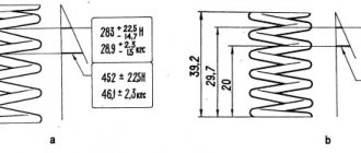
Scheme for pulling cylinder head bolts on VAZ “classics”
Also, due to overheating, the gasket can heat up to temperatures at which it changes its geometry. Naturally, in this case depressurization will also occur. This is especially true for iron-asbestos gaskets.
Another reason is a violation of the tightening torque of the bolts. Both very large and small torque values have a detrimental effect. In the first case, the gasket may collapse, especially if it is made of low-quality materials. And in the second, exhaust gases pass out without obstructing them. In this case, gases together with atmospheric air will have a detrimental effect on the gasket material, gradually destroying it.
As a rule, the tightening sequence is to tighten the central bolts first, and then the rest diagonally. In this case, twisting occurs in stages. In particular, in VAZ cars of “classic” models, the torque step is 3 kgf. That is, all bolts in the specified sequence are tightened to 3 kgf, after that they are tightened to 6 kgf, and to 9.10 kgf.
And the most obvious reason is the poor quality of the material from which the gasket is made. Everything is simple here. Try to buy products from trusted stores. When choosing, you must be guided by the “golden mean” rule. The gasket, of course, is inexpensive, so you shouldn’t overpay, nor should you buy downright cheap garbage. The main thing is that you are confident in the store where you are making a purchase.
It is also possible that the head gasket burned out simply from wear and tear of the material, because everything has its own service life.
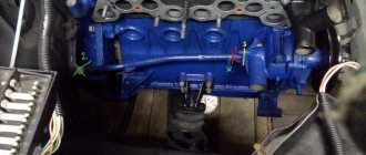
Examples of cylinder head gasket breakdown locations
Also, sometimes the reasons for the operation of the gasket are problems with disruption of the fuel combustion process (detonation, glow ignition). The cylinder head suffers greatly due to overheating. Cracks may appear in it, which will also lead to depressurization of the described systems. The head is usually made of aluminum.
Often when a gasket fails, it burns along the surround or between the cylinders. In this case, erosion of the surface of the cylinder block and the surround itself often occurs near the damage. A change in the color of the gasket material near the surround may also indicate high temperature in the combustion chamber. To eliminate the problem, it is often enough to set the correct ignition angle.
It is important for the driver to understand the difference between the concepts of “breakdown” and “burnout” of the gasket. Breakdown in this case implies significant damage to the surface of the gasket or its individual elements
In this case (and most often this is what happens), the driver is faced with a burnout. That is, minor damage occurs, which is sometimes even difficult to find on the gasket. However, they are the ones who cause the unpleasant situations listed above.
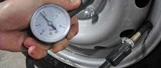
Suitability test
After removing the part, you need to check the element for clogging. Oil can carry small particles and other contaminants that can negatively affect the performance of the device in question. Their excessive accumulation causes unstable operation of the plunger rod and its jamming.
You can clean the tensioner yourself without much effort. Place the part in a tank of gasoline for several hours, rinse and dry it thoroughly.
When inspecting the case, you need to pay attention to the presence of dents, cracks and scratches. The plunger mechanism is checked in the same way.
If no visible damage is detected, check the functionality of the device.
The device is taken in one hand, and with the other we try to move the plunger rod in the frame. It should move freely without getting stuck. If movement is difficult, the washing process must be repeated. If this does not help, the part must be replaced. The element is installed in the reverse order of removal.
Replacing the cylinder head gasket Niva Chevrolet - niva chevrolet (VAZ 2123, Chevy)
niva chevrolet
repair manual
Also interesting: A unique 1977 Niva went on sale - it was rated as a new Land Cruiser Prado - read the News section in Avto.ru Magazine
| The cylinder head gasket is replaced if it is damaged. |
| The main signs of damage to the head gasket: |
| – insufficient compression (below 1 MPa (10 kgf/cm2)) in one or more cylinders; |
| – breakthrough of gases into the cooling system (seething, foaming of liquid in the radiator, rapid drop in the liquid level in the expansion tank in the absence of external leaks); |
| – coolant entering the lubrication system (emulsion on the oil level indicator, stratification of oil drained from the crankcase - especially noticeable in a transparent container); |
| – oil getting into the cooling system (oil film on the surface of the liquid in the expansion tank). |
| You will need: a torque wrench, a screwdriver, pliers, wrenches (regular and socket) “8”, “10”, “13”, “17”, E-Torx head. |
| 1. Remove the cylinder head cover (see here). |
| 2. Drain the engine cooling system (see here). |
| 3. Reduce the pressure in the power system (see here). |
| 4. Disconnect the throttle drive cable from the throttle assembly and receiver (see here). |
| 5. Remove the bearing housing together with the camshaft from the cylinder head studs (see here). |
| 6. Remove the valve drive levers, unscrew all the hydraulic mounts of the levers from the holes in the cylinder head (see ibid.) and... |
| 7. ...remove the oil supply ramp to the hydraulic mounts. |
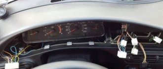
| 8. Disconnect the wiring harness connectors from the throttle position sensor,... |
| 9. ...idle air control,... |
| 10. ...coolant temperature sensor of the engine management system. |
| 11. Disconnect the injector wiring harness connector. |
| 12. Disconnect the wiring harness from the knock sensor. |
| 13. Move the motor harness to the side. |
| 14. Disconnect the wires from the spark plugs. |
| 15. Slide the protective cap and disconnect the wire from the coolant temperature gauge sensor. |
| 16. Disconnect the exhaust pipe from the exhaust manifold (see here). |
| 17. Unscrew the upper bolt securing the intake pipe strut and, loosening the lower bolt securing the strut, move it to the side. |
| 18. Loosen the fastening clamp and disconnect the adsorber purge hose from the throttle assembly. |
| 19. Loosen the fastening clamps and disconnect the radiator hoses of the cooling system from the cylinder head pipe,... |
| 21. ...side thermostat pipes. |
| 22. Loosen the fastening clamp and disconnect the fluid supply hose to the heater radiator from the cylinder head pipe. |
| 23. Unscrew the nuts of the fuel pipes and disconnect the fuel supply and drain lines. |
| 24. Remove the upper bolt securing the rear intake pipe strut, loosen the lower bolt of the strut and move it to the side. |
| 25. Unscrew the two nuts securing the starter heat shield and... |
| NOTE This is where the heat shield mounting nuts are located (for clarity, the nuts are shown on the removed cylinder head). |
| 26. ...move the shield to the side. |
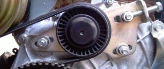
| 27. Remove the chain tensioner (see here). |
| 28. Disconnect the power steering pump bracket from the engine (see here) and move it to the side along with the pump. |
| 29. Remove the chain from the camshaft sprocket and... |
| 30. ...carefully place it on the tensioner shoe. |
| NOTE Make sure that the chain does not become disengaged from the oil pump drive shaft sprocket. |
| 31. Remove ten cylinder head bolts. |
| NOTE The bolt heads are E-Torx, but if necessary, you can use a 13mm socket. |
| 32. Remove the cylinder head and... |
| NOTE It is more convenient to remove the cylinder head with an assistant, as it is quite heavy. |
| 33. ...the gasket located underneath it. |
| 34. To determine the cause of gasket failure, carefully inspect it. On the edging of the gasket holes, traces of burnout will be visible between the combustion chambers of adjacent cylinders,... |
| 35. ...between the combustion chamber and the cooling system jacket channel or... |
| 36. ...between the combustion chamber and the lubrication system channel. |
| 37. Thoroughly clean the surface of the block from any remnants of the old gasket. |
| 38. Remove foreign deposits from the cooling system jacket passages (if any). |
| NOTE The photograph shows the removal from the channel of the cooling system jacket of a fragment of sealant that got into the system when it was used incorrectly during engine repair. |
| 39. Install a new gasket on the cylinder block, centering it on the two guide bushings. |
| Figure 4.8. Procedure for tightening the cylinder head bolts |
| 40. Install the cylinder head, centering it along the two guide bushings, screw in the bolts securing it and tighten them in four steps in a certain sequence (Figure 4.8): |
| – preliminary torque 20.0 N m (2.0 kgf m); |
| – tighten with a torque of 69.4–85.7 N·m (7.1–8.7 kgf·m); |
| – finally tighten it to an angle of 90°. |
| 41. Install all removed parts and assemblies in the reverse order of removal. |
| NOTE Tighten the camshaft bearing housing nuts in the sequence shown in Fig. 4.6, the moment specified in appendix. 1. |
Video [email protected] Copyright holder: Publishing House "Third Rome" Source: Repair manual for VAZ-2123 Chevrolet Niva |
Replacing the chain drive
- Place the car on a level surface. Open the hood. Disconnect the battery. Remove the air filter.
- The choke cable should be disconnected and moved away. It is also necessary to disconnect all electrical drives and pipes.
- Remove the fan, generator belt and pump roller. The belt should be thoroughly examined. If deep cracks or other damage is found on it, it must be replaced with a new one. Remove the tray protection and thoroughly clean its cover.
- Remove the valve plug. Unscrew the camshaft sprocket screw.
- Take a wrench and unscrew the ratchet nut.
- Now we begin to rotate the crankshaft until the marks on it and on the engine casing completely coincide. Make sure that the marks also match on the bearing housing and camshaft sprockets.
7. Then remove the casing covering the motor. To do this you will have to remove several bolts. We remove the sedative. Unscrew the screw securing the oil supply pump. There is no need to remove the screw. It should only be loosened and left in place.
8. We begin to remove the tension element mechanism. We remove the MM line, remove the pressure sensor, after which you can remove the tensioner itself. 9. Remove the screw on the camshaft gear. We remove the gear. After this, remove the timing chain. At this point, the parsing process can be considered complete. Now let's assemble the mechanism. 10. We take the purchased oil seals and begin to install them in place of the old ones. First of all, we change the crankshaft oil seal. After removing the old component, clean the installation location and install a new oil seal. First, it is recommended to lubricate the new oil seal with engine fluid, for example. 11. Now we take the chain in our hands and also begin to lubricate it. After this, we put the drive on the crankshaft gear, the oil pump and then the camshaft. This sequence must be followed. When tensioning the chain, you need to ensure that the alignment of the marks is not disrupted.