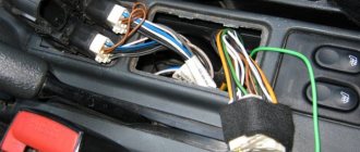
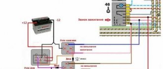
Connection diagram for fuel level sensor VAZ 2114
7.13.4.2. Checking the sensor and fuel level indicator
The indicator needle does not deviate from the beginning of the scale, regardless of the amount of gasoline in the fuel tank.
Fold down the rear seat and remove the indicator sensor hatch cover. Disconnect the pink wire from the pointer sensor and connect it to ground. Turn on the ignition:
– the pointer arrow has deviated – the sensor is faulty (replace);
– the pointer arrow does not deviate – continue troubleshooting.
Remove the instrument cluster from the panel without disconnecting the pads from it. Turn on the ignition. Connect the wire to the right contact 4
fuel level indicator (which connects to pin
10
of the red block):
– the pointer arrow has deviated – there is a break in the wire connecting the pointer and the sensor;
– the pointer arrow does not deviate – replace the pointer.
The indicator needle is on the scale regardless of the amount of gasoline in the fuel tank.
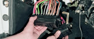
Disconnect the red block with wires from the block 3
instrument clusters. Turn on the ignition:
– the pointer arrow has deviated to the beginning of the scale – the pointer is working;
– the pointer arrow does not deviate – the pointer is faulty (replace).
The tachometer and speedometer can only be checked on stands in specialized workshops.
We present two diagrams for connecting the fuel level sensor of VAZ 2108, 2109, 21099 cars and their modifications with a carburetor engine.
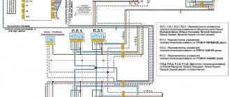
Electrical diagram for connecting the fuel level sensor for VAZ 2108, 2109, 21099 cars with mounting block 17.3722 and a “low” instrument panel (before 1998 onwards)
Electrical diagram for connecting the fuel level sensor for VAZ 2108, 2109, 21099 cars with mounting block 2114 and a “high” instrument panel (after 1998 onwards)
Features of the fuel level sensor connection diagram
Notes and additions
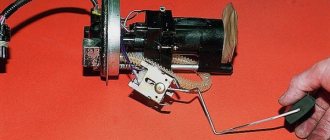
— The fuel level sensor (FLS) of VAZ 2108, 2109, 21099 cars is installed in the gas tank on the fuel intake. It is a float rheostat that changes its resistance depending on the position of the float. Read more: “Fuel level sensor for VAZ 2108, 2109, 21099 cars.”
More articles on the fuel system of VAZ 2108, 2109, 21099 cars
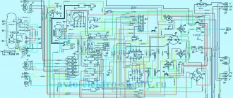
Click to enlarge (600 KB)
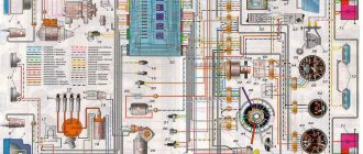
Description:
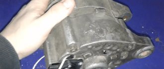
1 — headlight block VAZ 2114; 2 — gearmotors for headlight cleaners*; 3 — fog lights*; 4 — ambient air temperature sensor VAZ 2114; 5 — sound signals of VAZ 2114; 6 — engine compartment lamp switch; 7 — electric motor of the VAZ 2114 cooling system fan; 8 — VAZ 2114 generator; 9 — sensor for low oil level indicator VAZ 2114; 10 — washer fluid level sensor; 11 — front brake pad wear sensor; 12 — wire tips connected to the common windshield washer pump**; 13 — windshield washer pump VAZ 2114; 14 — headlight washer pump*; 15 — wire ends for connecting to the rear window washer pump on VAZ 2113 and VAZ 2114 cars; 16 — low oil pressure indicator sensor; 17 — lamp for lighting the engine compartment of the VAZ 2114; 18 — wire lug for connection to the wiring harness of the engine control system or to the wiring harness of the ignition system on carburetor VAZ 2114 vehicles; 19 — windshield wiper gearmotor; 20 — starter VAZ 2114; 22 — coolant temperature indicator sensor VAZ 2114; 23 — switch for reversing lights VAZ 2114; 24 — low brake fluid level indicator sensor; 25 - battery; 26 — sensor for insufficient coolant level indicator; 27 — relay for turning on fog lights VAZ 2114; 28 — mounting block VAZ 2114; 29 — brake light switch; 30 — plug socket for a portable lamp; 31 — lamp for illuminating the hydrocorrector scale of the VAZ 2114 headlights; 32 — parking brake warning lamp switch; 33 — backlight lamp connection block; 34 — switch for instrument lighting lamps; 35 — steering column switch; 36 — alarm switch; 37 — relay for the heating element of the front seats of the VAZ 2114; 38 — ignition switch VAZ 2114; 39 — rear fog light circuit fuse; 40 - fuse for the circuit of heating elements for the front seats of the VAZ 2114; 41 - door lock circuit fuse; 42 — front ashtray illumination lamp; 43 — ignition relay VAZ 2114; 44 — cigarette lighter; 45 — glove box lighting lamp; 46 — glove compartment lighting switch; 47 — electric motor of the VAZ 2114 heater fan; 48 — additional resistor of the heater electric motor; 49 — heater fan switch VAZ 2114; 50 — heater switch backlight; 51 — lamp for illuminating the heater levers of the VAZ 2114; 52 — gear motors for electric windows of the front doors; 53 — right front door power window switch (located in the right door); 54 — gearmotors for locking front door locks; 55 — wires for connecting to the right front speaker; 56 — gearmotors for locking the rear doors of the VAZ 2114; 57 — wires for connecting to the right rear speaker; 58 — control unit for blocking the door locks of the VAZ 2114; 59 — wires for connecting to radio equipment; 60 — switch for headlight cleaners VAZ 2114*; 61 — switch for the heated rear window element of the VAZ 2114; 62 — relay for turning on rear fog lights; 63 — block for connection to the heating element of the right front seat of the VAZ 2114; 64 — switch for the rear fog lights of the VAZ 2114: 65 — switch for the heating element of the right front seat of the VAZ 2114; 66 — fog light switch VAZ 2114*; 67 — switch for external lighting lamps; 68 — switch for the heating element of the left front seat of the VAZ 2114; 69 — block for connection to the heating element of the left front seat; 70 — wires for connecting to the left front speaker; 71 — left front door power window switch (located in the left door); 72 — left front door power window switch (located in the left door); 73 — wires for connecting to the left rear speaker; 74 — side direction indicators VAZ 2114: 75 — lamp switch on the front door pillars; 76 — lamp switch on the rear door pillars; 77 — lampshade; 78 — canopy for individual interior lighting; 79 — block for connecting to the wiring harness of the VAZ 2114 electric fuel pump; 80 — trunk light switch; 81 — instrument cluster of VAZ 2114: 82 — trunk lighting lamp; 83 — display unit of the on-board control system of the VAZ 2114; 84 — trip computer VAZ 2114*; 85 — block for connecting the wiring harness of the engine control system; 86 — rear external lights of VAZ 2114; 87 — rear internal lights of VAZ 2114; 88 — block for connection to the rear window heating element; 89 — license plate lights; 90 - additional brake signal located in the spoiler of the VAZ 2114.
Connecting the fuel gauge VAZ 2106
The fuel level indicator (UK-193 type) works in conjunction with the BM-150 sensor installed in the fuel tank. The sensor is made in the form of a rheostat made of nichrome wire. The movable contact of the rheostat is moved by the float lever. At the end of the lever there is an additional contact that closes the warning lamp circuit when 4–6.5 liters of fuel remain in the tank.
The serviceability of the fuel level indicator sensor can be checked with an ohmmeter.
Data for checking the fuel level sensor
Amount of fuel in the tank
The instrument needle constantly shows a full tank
With the ignition on, disconnect the pink wire from the sensor. If the arrow returns to the beginning of the scale, the sensor is faulty. Otherwise, either the device is faulty or the wire is shorted to ground. To check, remove the instrument cluster (see Removing the instrument cluster), disconnect the gray wire with a red stripe from the indicator and turn on the ignition. If the arrow returns to the beginning of the scale, the fuel level indicator is working, but the wire is damaged.
The instrument needle constantly shows an empty tank
With the ignition on, disconnect the wire from the “T” terminal of the sensor and connect it to ground. If the arrow deviates, the sensor is faulty. If the arrow does not deviate, remove the instrument cluster (see Removing the instrument cluster) and disconnect the gray wire with a red stripe from the fuel level indicator terminal and connect it to ground. If the arrow deviates, the device is working, but the wire between the sensor and the fuel level indicator is damaged.
| « previous page 16.15.1.1. Coolant temperature gauge | to contents | next page » 16.15.1.3. Oil pressure indicator |
Copyright © 2007-2019 All rights reserved. All trademarks are property of their respective owners.
Hi all! A lot of time has passed since the publication of the entry “about the fuel level indication in classic Muscovites.” I bought a sensor for the tank, checked the operation on a device from a VAZ 2106 with a broken arrow - everything fits! =) then I was looking for a whole device for an inexpensive price. and finally found him. I bought it for 30 UAH, I think. I came home, took it apart, threw out the case - I don’t need it. I connected it again and once again made sure that everything was working and there would be no more chatter. and began to think about how to fit the Volga sensor to the Muscovite tank. Google advised me to screw it by eye and shorten the float rod using the same eye, and then put it in the tank for a long and tedious time and fill and drain gasoline. Well, either don’t cut the bar but bend it. I wasn’t happy with this approach at all - installing and removing and filling and draining is a damn chore. It’s like transferring rice with Chinese chopsticks - interesting, funny, but not for the lazy. so I decided to make a layout. I built a model and marked on it the measurement boundaries of the native device and the Volgov one. I looked, twisted and realized that my knowledge of geometry would not help here - the maximum angle between the extreme positions of the float is different. The angles of the float rod in the upper and lower positions relative to the axis of rotation are different. the axis of rotation of the float rod is also at different heights relative to the mating plane of the device. That’s why I decided not to take my brain out and not engage in theoretical calculations. Therefore, without thinking twice, I hit the float rod of the Volgov device at the bend. I twisted it, applied it and realized that without a reliable fixation there was nothing to do. My brain was already tired and I decided to sleep with all these thoughts - the morning is wiser than the evening. and then moving to another apartment, all the components miraculously ended up in different bags/boxes/bags, then “acclimatization” in a new place and for a long time I could not find the VAZ device. besides, there was no time for that - I was seriously involved in luxury... in general, there are a lot of excuses =) and by the way, the photos were also lost, but that’s okay - I took a photo again and, in principle, everything will be clear. In general, the day before yesterday was a very good day - I climbed onto the closet to get a box containing spare parts from my Mercedes DTM model, which I had to assemble by buying magazines with spare parts, and here it is happiness! floats, hooks, spoons and other fishing accessories that I have been looking for since moving and the treasured fuel level device from 2106! and today I had some free time and I took up this issue. The crap from the central locking system that connects the rods was found in the garage in advance. the layout was ready. layout - a piece of fiberboard screwed to a block. block - a mating plane and a reference point for determining boundary levels - lower the sensor float, mark the lowest point - this is the lower level. draw a line through this point parallel to the level of the bar. Now we clearly see the lower level. with the top one it’s the same, only the top point is the bottom point of the float in the top position. I’ve already forgotten what I scribbled there, so first I screwed on the original sensor and checked the levels for it.
these levels are the standard for further manipulations with the Volgov sensor. Then I decided to go straight ahead - stupidly screw the float on the lower level and see what happens to the upper one. I screwed it on using a rod connector just like this.
set the lower level
Right the first time! everything came together perfectly! in fact, the float on the previous two foresails is clearly in line when viewed parallel to the float. in the photo the angle is slightly different and the gap from the float to the layout gives such a difference. we move from design to laboratory tests =) we take a 12V power supply, some wires and assemble everything according to the diagram - +12V to the device, ground and output to the sensor. to the ground sensor and wire from the device. I decided not to touch the light bulb for now. Plug the power supply into the socket, move the float - it works. Now comments under the photo.
Why does the sensor give incorrect readings?
The fuel level sensor of a VAZ 2114 car may not work correctly, giving false readings, for the following reasons:
The fuel gauge indicator always shows that the tank is completely full if the float has come off the sliding contact. In addition, such a malfunction may be due to the fact that the wire that goes to the instrument panel has a short, causing the resistance in the circuit to decrease.
Why the sensor may not show
Cases when the fuel level sensor does not work on a VAZ 2107 are not at all uncommon. Experienced owners of 7s know what can cause a device to break down. Moreover, sensor breakdowns occur equally often on both carburetor and injection VAZ 2107 models.
The fuel level sensor or FLS is a rheostat made of nichrome wire. The position of the moving contact is changed using a float. The device is located on both injection and carburetor models inside the tank. The only difference is that the injection sevens additionally have a fuel pump, which is located next to the sensor. If the fuel gauge does not work, then there is a high probability that there is a malfunction of the sensor in the tank.
Failures of this device manifest themselves in different ways:
- The pointer indicator is constantly in the “0” position.
- When the car moves, the needle tends to “jump,” which also indicates a malfunction in the fuel level control system.
- When the ignition is turned on, the needle on the fuel level indicator is at zero, but when driving, after a while it begins to function.
- The indicator (light) does not light up, indicating that the amount of fuel in the tank is reduced.
What causes the fuel quantity indicator in the tank on the seven to not work needs to be disassembled in detail, this will help you find out where to start repair work. The causes of breakdowns are:
- The sensor fuse has blown - this element must be checked first so that you do not have to do unnecessary work. If the fuse is blown, the dial indicator will always show “0”.
- The board tracks are worn out - this type of malfunction is directly related to the sensor on which the tracks are erased due to their wear-out. This type of breakdown is not considered serious, as it can be easily fixed. To do this, you need to bend the slider so that it moves along the section of the track that has not yet been erased.
- If the true fuel level in the tank is distorted, it is necessary to adjust the sensor regulator. To solve the problem, you will need to change the position of the FLS pins. Changing the position of the pin is done by moving it to the side until the pointer arrow moves to “1”. The arrow in positions “0” and “1” must be stationary, and if it moves when installed in these positions, then it is necessary to bend the pin accordingly.
- Oxidation of the FLS contacts, which also causes the indicator to become inoperable. To eliminate the breakdown, you will need to clean the contacts.
- The sensor float is damaged - depending on the fullness of the tank, the float moves the moving contact of the rheostat to the appropriate position. The float is a sealed volume of air. If the integrity of the float is compromised, fuel gets inside, which results in the display of incorrect data.
Only after it has been determined why the fuel indicator is not working can the appropriate repair actions begin. However, to identify a breakdown, you will need diagnostics, which every owner of a domestic car can carry out.
Checking the fuel level sensor
Before replacing the fuel level sensor on a VAZ 2107, it is recommended to first verify the causes of the breakdown. Further manipulations should be carried out according to the instructions:
- You need to disconnect the pink wire from the sensor located inside the gas tank. In this case, the ignition must be turned on.
- If the arrow previously displayed a full tank, and after disconnecting the wire, the arrow on the fuel level indicator dropped to “0,” then the sensor itself is faulty.
- If the arrow displays a full tank when the wires are disconnected, this means that the indicator itself in the instrument panel is faulty.
- To check the pointer, you will need to remove the instrument panel, find the wires that are connected to the device and disconnect the gray wire with a red stripe.
- After disconnecting the wire, you need to turn on the ignition and observe the location of the indicator arrow. If the arrow deviates to zero, this means that the pointer is working properly, and the cause of the breakdown is a violation of the integrity of the wire.
The following situation is when the indicator displays that the tank is empty. Before checking the FLS on a VAZ 2107, it is recommended to fill the tank full. This will allow you to perform diagnostic procedures with maximum accuracy.
- Disconnect the wire from the sensor that is connected to contact “T” and connect it to the ground of the car, first turning on the ignition.
- If after performing this procedure the arrow on the indicator deviates, then this is the main sign of a sensor malfunction.
- If the arrow is in place, then you need to disconnect the gray wire with a red stripe from the pointer. This wire also needs to be connected to ground.
- If after performing such actions the arrow has moved, then this indicates that the device is working properly, and the reason that the indicator does not show the fuel level in the tank is damage to the wire. The wire can be tested with a tester.
Having found out the cause of the malfunction, you should immediately begin repairs. If the fuel indication sensor on a VAZ 2107 is broken, then it needs to be replaced.
Replacing the fuel level sensor
The fuel sensor on the seven with an injector changes as follows:
- First you need to disconnect the negative terminal from the battery.
- Disconnect the fuse from the pump circuit, which is marked F.
- In the luggage compartment, you need to dismantle the trim on the right side to get to the location of the fuel pump, which will allow you to gain access to the gas tank hatch, in which the pump on injection cars and the sensor are installed.
- All hoses and wires must be disconnected from the fuel pump.
- The bolt is unscrewed, with which the steel clamp that secures the tank is attached.
- Remove the tube from the fitting through which the gas tank is vented. The clamp on the tube must first be loosened.
- You need to unscrew the plug from the gas tank hatch (filler neck) and then remove the rubber gasket from the neck.
- The ground wire is unscrewed and held in place by one of the 6 nuts. The remaining fastening nuts are unscrewed.
- To remove the sensor from the gas tank, the latter will need to be tilted slightly away from the body wall.
- Remove the structure on which the FLS is mounted.
Now you need to install a new one instead of the old sensor. It is important to take into account the model of the device, since the markings are different for injection and carburetor models. Installation of a new device is carried out in the reverse order of removal. In this case, it is important to pay attention to the condition of the sealing cuff. It is recommended to replace it with a new one, but usually it is sold assembled with the FLS.
At this point, the process of replacing the FLS is completed, and after completing the work, its functionality should be checked. The estimated cost of a new device is 500 rubles, but it all depends on the device manufacturer.
Self-replacement
Remember that the fuel level sensor on the VAZ 2114 is located near the fuel, which means you need to follow safety precautions. First turn off the battery. It is not necessary to completely dismantle it; you just need to disconnect the negative wire. Make sure the tank is no more than 45 percent full. This will greatly simplify the replacement procedure.
Procedure
The broken device is located directly in the fuel tank. Follow this algorithm:
Now you only need to replace the removed meter with a new one and repeat all the above procedures in reverse order.
Replacing the fuel sensor
Remove the plastic gas tank trim.
1) Disconnect the two wires from the sensor terminals, having previously marked their location.
Replacing the fuel sensor VAZ 2101-2107
2) Use a Phillips screwdriver to loosen the screw securing the fuel hose clamp and remove the hose from the fuel intake fitting.
3) Using a key set to “7”, unscrew the six nuts and 4) carefully remove the sensor from the gas tank.
Install the new sensor in reverse order.
5) Install a ground wire under one of the sensor nuts.
Checking the device with an ohmmeter
It is not always necessary to immediately replace the sensor with a new one. It happens that the problem lies in a completely different component of the car, for example, an injector. Also, if the meter is faulty, it may be possible to repair it. Before replacing, check the sensor:
If in at least one position the readings obtained diverge from normal, repair or replace the sensor. After installing the new meter, make sure that the installation arrow on the module cover is directed towards the trunk. Otherwise, you will need to dismantle the system again and repeat the replacement.
Self-repair of the fuel level sensor
Even an ordinary motorist can repair the FLS in a VAZ 2114. Spare parts for the sensor are sold at an auto supply store. You need to remove the device from the tank and familiarize yourself with its parameters. The marking is located on the front of the plate, directly above the rheostat scale.
If there is a hole in the float, then it will be easy to fix the problem. Pull the float out of the retainer socket and install a new one. If the rheostat scale strips are dirty, they need to be cleaned. The plate must be cleaned with a soft cloth or cotton wool soaked in alcohol. If the wires come off, they can be carefully put back in place by soldering. A cracked plate needs to be replaced with another one.
Operating principle of FLS
The principle of operation of fuel level sensors is classic and simple - changes in the position of the float are “read” by the control device and transmits the information via a digital or analog signal to visual control devices. The accuracy of the data determines the type and design features of the control equipment.
We recommend: How to properly operate a diesel engine in winter?
Lever type
The interaction of sensor elements of this type is presented as follows:
- the float constantly occupies the upper fuel level;
- a potentiometer connected to the car’s electrical network through an indicator on the dashboard, when the gas tank is completely filled, creates a resistance of about 7 Ohms, which corresponds to the “P” mark on the control device;
- when the engine is running, gasoline is consumed, reducing the amount of fuel in the tank - the float drops along with the drop in level, moving the potentiometer slider;
- the movement of the latter along the resistive plates smoothly increases the resistance to 230 - 340 Ohms (depending on the characteristics of the car), where the maximum value informs about a completely empty tank.
The reliability of this design has been proven over years of use. At the same time, the accuracy of the readings deteriorates over time due to wear of the resistive plates and the slider.
Tubular type
The operation of a tubular type sensor uses a control principle similar to the acquisition of information by lever systems, but there are fundamental design differences. Its main elements are presented:
- Housing with guide post and resistive wire.
- Float equipped with slip rings.
- Device mounting flange with a contact group for connecting control wires.
Fuel level control is carried out in the following order:
- fuel enters through a hole in the lower part of the body;
- as the tank fills, the float mechanism moves and will remain at the top point;
- its movement changes the resistance and, therefore, the tank fullness indicator on the indicator;
- at the top point, a small section of the contact wire is involved, and the resistance has a minimum value, at the bottom - the length increases, with a corresponding increase in the final indicators.
Placing the float in a limited space that smoothes out vehicle vibrations provides information about the fuel level more accurately than lever-type units. But the possibility of installation on cars is limited by the design features of fuel tanks.
Electronic (contactless)
Electronic fuel level sensors are installed in the tank when using modern types of ethanol-based, methanol-based gasoline or biodiesel, since the installation of contact units for level determination is not effective - the readings are inaccurate, and the wear of parts is high. In turn, the inactive magnetic fluid position sensor copes with the task successfully and has the following features:
- The executive part is located in a sealed housing; only the magnetic float and lever come into contact with the fuel.
- Fuel height measurements are carried out by a signal generated by a magnetic field.
- Changes are recorded by predetermined segments, the passage of which changes the amplitude of the feedback signal. So, when filling the tank “to full”, the sensor will change readings only after passing the next mark, and the driver will not be able to observe the smooth drop in level.
Important! If you can choose a sensor to install to replace a damaged one, it is preferable to choose a model with digital information transmission - its data has less error than analog devices.
In order not to be left without fuel in the middle of the journey, you need to know the amount of fuel in the tank. Thanks to the device, you can understand whether or not you need to visit a gas station, how much gasoline is in the tank, and whether you can continue driving. This is not just a useful device, but a device responsible for the level of safety on the road. Modern legislation requires the presence of such a sensor and its good condition.