Connection diagram for sound signals via relay
Most models developed by VAZ, including the VAZ 2108, VAZ 2109 and VAZ 21099, which are still widely used today, are equipped with not very euphonious sound signals, which often confuses the owners of these cars. Meanwhile, nowadays there are quite a lot of quite worthy replacements for the standard VAZ signal and, in particular, the option of installing an excellent sound signal from the Volga can be an excellent alternative. So, to implement such a not too expensive idea, we will need the following equipment and related materials:
- Conventional “Volgov” dual signals with ground output to the housing;
- Relay type 90.3747 together with a block and mounting flange;
- Set of wide terminals;
- 20A fuse together with mounting block;
- Multi-core insulated wire with a cross-section of at least 2.5 mm. sq.;
- Heat-shrinkable tube or electrical tape;
- A piece of aluminum or steel angle.
Practical implementation of the modification
As always, before working with the car’s electrical circuit, you should disconnect the “negative” power wire terminal from the battery, thereby protecting yourself from accidental short circuits.
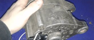
Next, in order to gain access to the standard signal, it is necessary to completely remove the radiator grille, after which it becomes possible to dismantle the sound device (along with the mounting bar). Don't forget to also disconnect the signal ground wire.
Having assessed the installation location of the standard signal, we modify the mounting of the signals from the Volga using a purchased corner on which we drill holes in accordance with the markings at the installation site. If our corner is made of steel, we cover it with a layer of paint to protect it from corrosion. When attaching signals to the corner, we take into account that one of the mounting bolts will serve as a mass, which means it must be of the appropriate length to ensure reliable contact with the metal part of the car body.
We fasten the corner with the new signals using the bolt securing the standard signal (again, remembering the “ground”, you can use a castle washer). If the fastening bolts on the corner interfere with installation (the bolts touch the radiator), we make adjustments by placing washers.
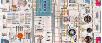
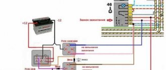
The connection diagram for Volga signals to a VAZ is as follows:
To make a reliable connection, we crimp the ends of the wires used with terminals, and protect all exposed areas with heat-shrinkable tubing or electrical tape.
As for the relay, there is a place for it on the back of the radiator in close proximity to the headlight unit.
We attach the “negative” wire of the relay (pin 86), equipped with a ring terminal for a screw, to the car body through a castle washer (after having previously stripped the metal at the connection point).
We connect the wire from the 30th contact of the relay (going through the fuse) to the “positive” terminal of the battery, in other words, the main power supply for the signal will be supplied directly from the battery.
The sound of new signals can be adjusted using a special bolt on the housing. In addition, the signal sockets should be positioned in such a way that moisture does not accumulate in them, and it would not hurt to protect all bolted connections with lubricant.
It should be noted that the installation of a Volgov signal on a VAZ can be carried out according to a simplified scheme, that is, without the use of an additional relay. In this case, the connection is made using the standard signal power wires, taking into account the fact that the basic signal uses its own relay located in the fuse block. This method is of course simpler and less expensive, but it has certain disadvantages. The fact is that the positive wire feeding the standard signal is too thin for a more powerful “Volgov” device and the voltage drop across it is too significant (the signal will sound weaker than we would like). In addition, the protective fuse in the standard network protects not only the signal circuits, but also the fan, and its 5A rating is clearly not enough (when both devices operate simultaneously, the fuse quickly burns out and, at the same time, the tracks on the circuit board of the fuse box are often damaged).
Fig.1. Electrical diagram.
Rice. 2. Relay mount.
Rice. 3. Location of the sound signal.
Update dated September 22, 2009, by Rusich.
I will also contribute to the installation of new sound signals. Based on the price-loudness ratio, two different-tone Volga signals were purchased, of which, as is known, the central contact pin is mass, and the plus is separate.
Everyone who previously wrote to FAC put signals under the hood - but, gentlemen, the volume is lost! I also spent a long time trying out how to install it in a regular place, and in the end I used a plastic cylinder for an additional one. fan Both signals stood wonderfully against its wall, one above the other. And I screwed the relay onto a pin from the old one - just so as not to bother with the wires of the old signal and just throw them on the two legs of the relay winding.
The red wire is simultaneously connected to the contact group, and the second contact gives us the required voltage for the signals.
For reliability, I ran the mass with a separate wire, cleaned everything and lubricated it with UPS (universal penetrating lubricant (similar to WD-40), including the signals, since the parts are made of cardboard.
An hour of work - voila - in the middle of the grille, Volga signals are buzzing with bells facing outwards
Update from 09/19/15, by SKArt 4X4.
Installation of Volga signals for the lazy.
I bought Volgov signals because it’s depressing:
The size and weight of the signals baffled me: I don’t know welding, I only considered mechanical assembly work. After thinking and figuring it out, I installed it as shown in the photo, using a “U”-shaped bracket from the fog lamp. The voltage is supplied through a conventional 4-pin relay.
PS The first attempt to install each “pipe” on 2 plates resulted in the plates breaking after 16 months. Now I installed each signal on 4 plates.
Occasionally there is a need to use the sound signal. And as you know, Niva’s native signal is weak and sometimes people don’t pay attention to it. Situations have already arisen several times when I wanted to make a louder statement about myself. But usually you just don’t press the signal, because there’s practically no reaction.
I decided to rectify the situation - replace the original sound signal with a Volgovsky (GAZ) two-tone one. This is one of the classic modifications of the Niva (and not only). On occasion, I purchased a set of signals for 610 rubles.
Air signal connection
If you need to connect not an electric, but an airborne sound signal, the connection procedure will be almost the same as described above. The difference is that the wire from the relay does not go to the sound signal itself, but to the compressor (the engine that supplies air to the signal). And the pneumatic signal pipes are connected to the compressor through tubes.
When you press the horn, air from the compressor is supplied to the horns. With the help of a membrane installed in them, a sound signal is obtained.
You can read about how to connect the headlights yourself in our article How to connect the headlights.
FakeHeader
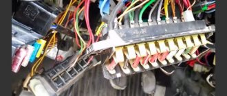
That's it, the mechanical part is over, let's move on to the electrical part. As a rule, the horn device is located behind the engine radiator grille, directly in front of the main radiator device. As practice shows, often the cause of failure lies in their oxidation, so it makes sense to clean the contacts. Already crimped wires with terminals are sold in stores.
Using this circuit, you can connect almost any powerful device and control it with a small, beautiful key. I planned to do it from the front, instead of the standard one, but I couldn’t unscrew the grille mounting bolts.
Connecting an air signal If you need to connect not an electric, but an air sound signal, the connection procedure will be almost the same as described above.
To do this, you will need to dismantle the relay and set the resistance measurement mode on the multimeter. The difference is that the wire from the relay does not go to the sound signal itself, but to the compressor engine, which supplies air to the signal.
We mark the corner at the installation location, saw it off, and drill holes for attaching signals from the Volga.
This petal may burst over time; sometimes the cause should be sought in the jamming of the pressure rack. So we bring to your attention a diagram for connecting an audio signal through a relay. It is universal for most cars, with the exception of those cases when audio signals are used that receive mass through the body, for example Volgov's, for which the diagram is slightly different.
That's it, the mechanical part is over, let's move on to the electrical part. (easy and fast) Volgov Signals on VAZ 2107
How does a car horn work?
Let's consider a universal diagram of a car sound signal:
- The so-called anchor.
- Device rod.
- Nut for adjustment.
- Lock-nut.
- The first tungsten contact of the horn.
- Another tungsten contact.
- Capacitor element.
- Core.
- The housing that contains all the components.
- Activation button located on the steering wheel.
- Resonator disk.
- Membrane.
- Winding.
- This is a relay contact.
- Another anchor.
- Relay coil.
- Signals.
In accordance with the connection diagram, when the driver presses the control button, a current begins to pass through the winding, which ultimately magnetizes the core, which in turn attracts the armature. With this anchor, the rod that bends the membrane begins to move, and thanks to the nut, the contacts open, which helps interrupt the electrical circuit. All elements, in particular the disk, rod, anchor and others, return to their original position using a spring and membrane. In this case, the contacts close, which again leads to the passage of current through the winding. The process of opening the contacts is carried out by pressing the horn button on the steering wheel (the author of the video is the channel pribambas sender).
Possible malfunctions: signs and causes
By what signs can you determine that a car horn needs repair:
- The steering horn does not work. When the driver presses the steering wheel button, the sound device does not work.
- The device sometimes works, sometimes it doesn’t. When you press the button on the steering wheel, the horn first sounds and then disappears.
As for the reasons why a device may fail, there are many:
- A fuse located in the fuse block under the hood or inside the vehicle has blown. In case of such a problem, the operation of the horn can be restored, since it is not damaged. The car may also, in addition to the fuse, have a relay.
- The horn itself is broken. If you replaced the safety element, but this did not help solve the problem, then you need to check the horn itself. To do this, the device will need to be removed, and its contacts will need to be connected directly to the battery. When connected directly, a functional horn will sound.
- In some cases, the reason lies in the appearance of a short circuit in the vehicle's electrical network. A short may affect the connection circuit, so you must first check the functionality of the fuse socket. Sometimes the horn may not work correctly due to circuit damage and current leakage.
- Also, the cause of the malfunction sometimes lies in worn-out clamping contacts located on the steering column. A malfunction of this type is more typical for domestic cars. As a result of long-term use, the springs begin to wear out over time, which leads to the fact that the impulse through them cannot be transmitted from the button to the buzzer itself.
- It also happens that the slip ring wears out right on the steering wheel.
- If the contacts are not worn out, then they could simply oxidize. Long-term use, as well as lack of maintenance, lead to deposits forming on the contacts over time. As mentioned above, this problem can cause difficulty transmitting the signal to activate the buzzer.
- The contact blades are located under the steering wheel hub. This petal may burst over time; sometimes the cause should be sought in the jamming of the pressure rack.
- The horn winding is burnt out.
- Sometimes the horn malfunction is due to a damaged electrical connection or an accidental disconnection of the terminal directly on the signal itself.
- Sometimes the reason for a non-working signal may be a break in the cable on the steering wheel on cars equipped with an airbag (video published by the channel Learning to drive a car. All secrets for beginners).
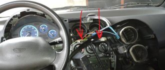
Installing an additional button on the VAZ 2107 sound signal
The moving contact between the steering wheel and the steering column of the VAZ 2107 fails over time. His foot loses elasticity and the contact parts no longer touch. To prevent such a situation, car owners often install an additional button to sound a sound signal, duplicating the functions of the button on the steering wheel, that is, connecting the relay to ground. It is installed in any convenient place, most often on the instrument panel near the steering wheel.
Often VAZ 2107 owners install an additional button to sound the sound signal.
An additional button is installed as follows.
- We make a hole of a suitable diameter on the instrument panel.
- We install the button in the hole made.
- If the button is three-contact, we determine which contacts close when it is pressed. This can be done using a multimeter.
- In the common wiring harness, we find the wire going to the ZS button on the steering wheel. This is usually a gray wire with a black stripe.
- We connect this or a wire parallel to it to one of the contacts of the button.
- We connect the second terminal of the button to ground.
A button connected in this way will repeat the functions of a button on the steering wheel.
We recommend: Rear view camera for cars: what they are, which one to choose
Personal experience shows that using the signal button installed on the instrument panel is inconvenient. You won’t be able to get used to it enough to promptly sound a beep without looking at it. As a result, precious fractions of a second are lost when they could be vital. It's worth spending the money and taking a little time to fix your steering wheel signal.
Do-it-yourself signal diagnostics and repair
How to check and repair the horn yourself? For diagnostics, you will need a tester (preferably a digital multimeter, but if you don’t have one, you can use a regular one), crimping pliers, pliers, and a utility knife. Prepare spare wiring and a service manual for the machine.
Checking with repairs is performed as follows:
- The functionality of the fuse and relay is checked; you need to find the mounting block. A more precise diagram is indicated in the technical documentation, but usually the safety device is located in the power supply unit; it can be installed in the dashboard. Once you have located the block, examine the diagram on the back of the block cover to find the fuse. Dismantle the device that is responsible for the operation of the horn and carefully inspect it - if there is an open circuit, this indicates that the fuse is not working.
- But if the device is intact, this does not mean that it is functional. You need to diagnose it using a tester. Set the multimeter to the resistance measurement mode with sound (if we are talking about a digital tester and it has such a function). If you have an analog multimeter, before diagnosing you will need to calibrate the tester; to do this, short-circuit its probes with each other and move the regulator to zero. Then press the tester probes against the contacts of the safety device. If the part is working, then the multimeter will show 0 Ohm, but if not, then if there is no change on the display, we can conclude that the resistance is too high. This indicates a broken fuse and the device needs to be replaced.
- After this, if the fuse is working, you need to find the relay block, which is located either in the engine compartment or in the interior of the car - use the service book to search. Typically the relays are located in the same fuse box. The easiest way to check the operation of the relay is to swap the devices with other similar parts. In most cases, relays are interchangeable, so if after replacing the device the horn starts working, then you can understand that the reason was in the relay.
- You should also check the steering horn switch; a tester is also used for this. If there is no power supplied to it, then of course the button will not be able to respond to pressing.
- Next, diagnose the functionality of the relay switch. To do this, you will need to dismantle the relay and set the resistance measurement mode on the multimeter. One contact from the tester should be brought to the relay switch connector, and the second is connected to the negative terminal of the battery. With this connection, the assistant must press the beep button. As a result, numerical values should appear on the display. If the message Out of Limits appears on the screen, this indicates that the switch is not in working condition, and accordingly, it needs to be changed.
- It would be a good idea to check the horn itself. As a rule, the horn device is located behind the engine radiator grille, directly in front of the main radiator device. Having found the mechanism, you need to determine which of the conclusions is positive and which is negative. Please refer to the technical manual to determine this accurately. Once you know this, connect the horn directly to the car's battery to check its operation. The positive contact is connected to the plus, the negative, respectively, to the minus. When the negative contact is connected, the horn should start working, but if the connection does not produce results, then the device is faulty.
- The next step will be to diagnose the circuit. If you have any suspicions about the health of the electrical circuit, you need to check the grounding of the circuit, as well as the voltage and current values. Determine the mass to accurately identify grounding; for diagnostics, set the tester to measure resistance in Ohms. Connect one contact of the multimeter to the minus of the circuit, and connect the second to ground. As a result, numbers should be shown on the tester screen - if they are present, the wiring is intact. At this stage, you need to check the condition of the contacts. As practice shows, often the cause of failure lies in their oxidation, so it makes sense to clean the contacts.
Does the sound signal on the VAZ 2110 not work?
Every car must have a working horn. Thanks to the horn, the driver can prevent an emergency situation on the road and avoid a possible collision. But it often happens that the horn refuses to work. For what reasons does the sound signal on the VAZ 2110 not work and how to fix this problem - read below.
There are several signs of a malfunctioning sound signal on a VAZ 2110 or 2112:
- The sound signal has disappeared. The driver presses the steering wheel or the corresponding button located on it, but there is no beep.
- The beep appears and disappears. When the driver presses the steering wheel, the signal may start to work, but then immediately disappears.
There may be several reasons why the horn refuses to function:
- One of the most common reasons is the failure of a safety device. In this case, the integrity of the horn itself will not be compromised, which greatly simplifies the repair procedure.
- Failure of the horn itself. If after replacing the safety device the sound does not appear, you can try to check the functionality of the horn by dismantling it and directly connecting it to the battery. If the device is working, then when connected to the battery it will begin to emit a corresponding signal.
- The reason may also be a short circuit in the vehicle's on-board network.
- Another cause of the problem may be worn out clamping contacts located on the steering column. This problem often occurs in the cars of our compatriots. In any case, the clamping contacts wear out over time due to use; this cannot be prevented. As an option, you can try to increase the service life of the contacts; to do this, they need to be treated with graphite lubricant from time to time.
- Worn slip ring on the steering wheel. As stated above, there is no escape from wear and tear, so sooner or later every car owner will face such a problem. As in the previous case, you can try to increase the service life of the slip ring by applying graphite lubricant to it.
- Oxidation of contacts on the steering wheel. With prolonged use, deposits will begin to accumulate on the internal contacts, which makes it impossible to transmit the impulse to activate the horn.
Methods for troubleshooting
If the horn circuit is broken and the horn stops working, then there are several options for solving the problem:
- First you need to diagnose the safety device. If this part is burnt out, then you just need to replace it with a new one; the device is located in the mounting block. The replacement process will not take much time; any car enthusiast can cope with this task. If replacing the fuse gave results, but after some time the horn stopped working again, then most likely the reason lies in voltage surges in the on-board network. Overload contributes to accelerated burnout of the fuse element, so you will have to look for the source of the load and solve the problem. To do this, use a multimeter or seek help from an electrician.
- If the horn itself malfunctions, the device must be replaced. If diagnostics by direct connection to the battery do not produce results, then most likely the reason lies in the device itself, which needs to be changed.
- Short circuit. To diagnose, you will need a multimeter and a little experience. Using a tester, you can find a short circuit, but if you have never encountered such a problem before, it is better to seek help from specialists.
- If the clamping contacts or slip ring are worn out, then the failed elements must be replaced. It is not a fact that you will be able to buy new contacts or a ring, so most likely you will have to change the horn assembly.
- Another reason why the horn does not work is oxidation of the internal contacts. Over time, as mentioned above, dirt and deposits accumulate on them, which leads to the obstruction of sound. You can try to disassemble the steering wheel of the car, then clean the internal contacts and assemble the steering wheel (the author of the video is the channel Alexander Amochkin Kolomna AAK).
If you are faced with the problem of a non-working horn, then you will probably be wondering how to replace it:
- First of all, you need to remove the steering wheel. To do this, remove the trim and unscrew the bolts that secure the steering wheel.
- After the steering wheel is removed, you can clean the contact tracks, perhaps this will help solve the problem. Make sure that the wire contacts in the column are as clean as possible .
- Unscrew the two screws located under the plastic cover. After dismantling the cover, you will be able to see the contact plate; there is a possibility that the problem lies there. Clean the contacts and check the signal functionality. If the horn does not work, then using a 24mm wrench you will need to unscrew the nut, but you do not need to unscrew it all the way.
- Next, the steering wheel itself must be pulled towards you; this will require some effort. You can try to move the wheel by tapping it from different sides. When you feel that the steering wheel has given way, the nut is unscrewed completely.
- After dismantling the steering wheel, we proceed to removing the horn. There is a module located under the grille of the radiator unit; it must be removed; to do this, unscrew the nut to 13 and disconnect the connector.
- Install a new one, replace the steering wheel and check the operation of the horn.
We recommend: What should be the voltage in the car’s on-board network?
Is a Volga horn good?
Is it possible to use a signal from the Volga in the “ten”, how to install it and how to connect it yourself? In the VAZ 2110 it is allowed to install a Volga horn, and the latter can be either old or new model. There is no particular difference between these details, except that the tonality will be slightly different. And, of course, the cost. But keep in mind that installation by simply replacing the device will not work.
The bottom line is that two cables are connected to the standard device - one with a negative output, which comes from the button on the steering wheel, and the other with a positive one. The latter is permanently connected; it also powers the ventilation device of the radiator unit.
But in Volga devices, only one cable is used - positive, since the mass in this case is supplied through the body, that is, from the attachment to the vehicle body.
In addition, you must also take into account that both systems use different current consumers - the standard options require no more than 5 amperes, while the Volga ones require 8 amperes each. The result is 16 amperes (video author - Master Bruce).
Accordingly, to correctly connect a product from Volga to a VAZ 2110, you will need a four-pin relay; you have several options for installing it:
- in the vehicle interior, in the mounting block with fuses;
- in the engine compartment, but in this case, please note that the relay should be securely insulated to prevent moisture from entering.
The feasibility of self-repair
So does it make sense to repair the horn yourself? If we take into account the recommendations described above, then the repair is advisable only if the car owner is as careful as possible when performing it.
After all, during the repair work, there is a high probability that an inexperienced car enthusiast will damage the wiring in the unit or connect the contacts incorrectly.
Therefore, if you have never encountered a repair procedure before, it is better to entrust this matter to specialists or simply replace the horn assembly.
“Installation of sound signals from Volga (GAZ) on VAZ 2110, 2112, 2111”
How to avoid mistakes when installing the Volga horn on the “Ten” - detailed instructions describing all the nuances are given below (the author of the video is Russian Man).
The article was useful. Please share the information with your friends.
Settings
- Devices
- WallSwitch
- Settings
| Settings | Meaning |
| First field | Relay name, can be edited |
| Room | Selecting the virtual room to which the device is assigned |
| Relay operating mode | Selecting the relay operating mode: |
- Pulse - WallSwitch, when activated, emits a pulse of a specified duration
- Bistable - WallSwitch, when activated, reverses the state of the contacts
Opens the script creation and configuration menu
Allows the user to disable a device without removing it from the system. The device will not execute system commands or participate in automation scripts. All device notifications and alarms will be ignored
The standalone controller CTV-CR20EM with a built-in Proximity card reader EM-MARINE is designed to build an autonomous access control and management system for one or two access points.
The controller is made of impact-resistant plastic and has an IP68 protection class, which allows it to be used in various climatic conditions. The stand-alone controller CTV-CR20EM is programmed from the remote control or using master cards that are supplied in the kit.
CTV-CR20EM supports 10,000 user keys and allows you to implement the “gateway” operating mode when using a second similar controller.
ATTENTION: The manufacturer reserves the right to make design changes not reflected in these instructions, which do not lead to a deterioration in the declared characteristics, at any time and without prior notice.
PURPOSE OF CONTROLLER CONTACTS
Pink wire RESET - used to reset settings Pink wire GND - used to reset settings Green wire D0 - Input for connecting the reader data circuit White wire D1 - Input for connecting the reader data circuit Gray wire ALARM - connecting a siren Yellow wire OPEN - Exit button or call button video intercom panel Brown wire D_IN - connection of the door open sensor Red wire + 12V - +12V power contact from the power supply Black wire GND - "Ground" and common negative Blue wire NO - relay contact, normally open (open) Purple wire COM - common relay contact Orange NC - relay contact, normally closed (closed)
ACS CONTROLLER CONNECTION DIAGRAM
Main modes 1. Using the device in standalone controller mode with a built-in reader.
2. Using the device in controller mode with connecting an additional reader with Wiegand26 output
CONNECTION DIAGRAM FOR TWO CONTROLLERS
Additional modes 1. Using the device in the mode of two controllers for one door. In this mode, the first controller is installed indoors and is used as a controller, the second is installed outside and is used as a reader. Enable GATEWAY mode on all devices. With this scheme, the number of users can be increased to 20,000. To combine user databases, the settings on the two devices must be identical, including the administrator master code.
2. Using the device in the mode of two controllers for two doors (“GATEWAY” mode) In this mode, install one controller on the first door, the second on the second. Enable GATEWAY mode on all devices. With this scheme, the system will work as follows: while the first door is open, the second will always be closed. After closing the first door, you can open the second one.
3. Using the device in Antipassback mode for one door. Install the controller indoors and the reader outside. Enable Antipassback mode in main mode. With this scheme, the system will work as follows: the user presents the card at the entrance and exit. The user will not be able to log in or log out twice in a row.
4. Using the device in Antipassback mode for two doors. Install the first controller on the first door and enable Antipassback mode in additional mode. Install the second controller on the second door and enable Antipassback mode in the main mode. The user will not be able to go through the same door more than once without going through a second door.
CONNECTION DIAGRAM OF THE CONTROLLER TO THE VIDEO DOORPHONE
The figure shows a diagram of connecting the controller to the calling panel of the video intercom and the electromechanical lock.
To connect the calling panel to the controller using an electromechanical lock, the following contacts are used: “COM” - common relay contact and “NO” contact - normally open relay contact.
The “COM” wire from the calling panel is connected to the “OPEN” controller contact
The “NO” wire from the video intercom calling panel is connected to the “NO” controller contact, and one of the wires from the electromechanical lock is also connected here. The second conductor of the lock is connected to the common “Minus” of the power supply. Thus, the lock will be opened both from the video intercom and using cards or keys programmed into the controller.
Note! For different manufacturers of calling panels, the colors of the “COM” and “NO” contacts may differ.
CONTROLLER INDICATION MODE
Standby mode - The indicator light flashes red. There is no sound indication.
Relay activation - Indication light lights green. The sound indication gives a short signal.
Entering programming mode - The indicator light turns red. The sound indication gives a short signal.
Successful operation - Indicator light turns green. The sound indication gives a short signal.
Error - There is no light indication. The sound indication gives three short beeps.
Exiting programming mode - The indicator light flashes red. The sound indication gives a long signal.
Alarm - Indicator light flashes red. The sound indication gives a continuous signal.
Lada 4×4 3D › Logbook › Klaxons from Volga to Niva
To replace the once lost signals, it was decided to install Volgov “snails”. From a technical point of view, I figured out how to do this in such a way that they would not be covered in mud and without perversions a long time ago, but I only got around to implementing it now. History in pictures:
1. I decided to install it on the left mudguard, under the spare tire with the signal bells directed outward through the radiator. So that the sound spreads outside the engine compartment.
4. From steel (St3) 2 mm thick, I cut out parts according to templates and processed them with a file.
5. Removed the terminals from the battery. 6. Installed the lower and upper support elements.
7. Using welding, I welded (with tacks) the wall of the traverse to the supporting elements. 8. I made a template for the second wall from cardboard. 9. I cut out the second wall in the metal and processed it with a file. 10. I welded all the seams on the workbench. 11. I cut out a bracket plate for direct mounting of signals and relays and welded it to the traverse.
14. Screwed the signals and connected them. Pressed. I almost vomited from the wretchedness of the sound. I thought a lot.
15. I secured the signals through the steel plates that came with them (before that, I tightened all the threaded connections on the signal housings, adjusting the sound with a screw and applying the signal to the battery).
16. Pressed. The sound is satisfactory. Almost as it should be. The signals are Chinese, so you can’t expect anything more from them.
All connections were covered with a thin layer of CIATIM-201 to ensure reliable electrical contact. The mounting holes were drilled with a diameter of 8mm.
Source
Shall we make some noise? Sound selection
How many times in one trip do you press the horn? Of course, this depends on temperament, but in dense traffic you can’t go anywhere without a sound signal - you have to indicate your presence on the road. True, the sound of standard “pipes” sometimes evokes melancholy, especially in small cars. Let's figure out how to choose and install more serious signals.
But first, a few words about their correct use.
Traffic rules: rules for using sound signals
Car horns have become an indispensable soundtrack to any city. Which is not at all great, because traffic rules directly prohibit the use of sound signals in populated areas unless absolutely necessary (to prevent accidents).
Traffic rules clause 19.10. Sound signals can only be used:
- to warn other drivers of the intention to overtake outside populated areas;
- in cases where it is necessary to prevent a traffic accident.
There is also a special road sign 3.26 “Sound signal prohibited.” It is intended for installation outside populated areas, where unnecessary noise cannot be made (in forests, in nature reserves), but it is also found in cities, where it simply duplicates the current rules - you cannot honk your horn in the city without a good reason even without this sign.
Unfortunately, drivers regularly violate this point of the rules: they use the horn to greet each other or express indignation, to attract attention or to hurry up someone who is unwary at a traffic light. In general, they buzz for any reason. Which not only increases general nervousness on the road, but also disturbs other people - the sound of the horn in the city spreads far and loudly, shielding it from buildings.
At the same time, the sound signal itself is necessary for the car and is even included in the “List of malfunctions and conditions under which the operation of vehicles is prohibited” - you simply cannot drive with a non-working horn (due to the impossibility of signaling to a pedestrian or another driver to prevent an accident). But you need to use it wisely and only for a compelling reason.
Do you agree to not make any more noise in the city? Then we move on to choosing “pipes” to replace the standard ones.
Design of signals. Electrics and pneumatics
Typically, a car has a pair of single-tone signals (high and low pitch), the sound of which is harmoniously superimposed on each other. The difference between their frequencies is 70–100 Hz, forming the desired sound depth. Structurally, car sound signals are divided into electromagnetic and pneumatic. In both types, sound is generated by vibrations of the membrane, but different forces set it in motion.
From the factory, most cars are equipped with electromagnetic signals , most often of a hornless (disk) design - “pancakes”. These signals are inexpensive to produce and take up little space, making them easy to place under the hood. You can’t get much power from “pancakes,” so motorists are replacing them with horn electromagnetic signals—“snails.” Thanks to their funnel-shaped geometry, they generate a very loud sound. The price to pay is massiveness: finding space for two “snails” in the engine compartment can be difficult.
In electromagnetic signals, a solenoid creates membrane oscillations. In pneumatic signals, the membrane is driven by compressed air, so their operation requires a separate device - a compressor capable of pumping air under pressure into the horn. The sound of such signals is noticeably more powerful than electromagnetic ones, but they take up more space than even the most massive “snails” - not every car can be installed.
In electromagnetic signals, a solenoid creates membrane oscillations. In pneumatic signals, the membrane is driven by compressed air, so their operation requires a separate device - a compressor capable of pumping air under pressure into the horn. The sound of such signals is noticeably more powerful than electromagnetic ones, but they take up more space than even the most massive “snails” - not every car can be installed.
A pneumatic signal may have several bells (“horns”) of different sizes; The more there are, the more powerful the compressor will be needed. The tonality of the whistle depends on the size of the bells - several “horns” will sound like a whole brass band. But don’t get carried away: according to GOST R 41.28-99 (UNECE rule No. 28), the sound signal should sound monotonously and continuously; installation of musical signals with overflows and melodies is prohibited.
"Volgov" signals
Why buy custom horns at all? Firstly, the standard ones often fail, and the original “pipes” are expensive. Secondly, their volume sometimes simply does not correspond to the realities of the road. Additional sound insulation is increasingly popular; in the summer everyone prefers to drive with the windows closed and the air conditioning running, and if the music in the cabin is also playing loudly... Your modest horn, installed by the automaker taking into account the requirements for reducing noise in cities, simply will not be heard. That's why motorists try to set the signal louder - it's often a matter of visibility and safety on the road.
But there are also standard horns with decent sound. In Russia, for example, the so-called Volgov signals are highly valued - Yuri Detochkin would approve of such a choice. The characteristic mixture of high and low frequencies (510 and 410 Hz) at 115 decibels sounds solid and “juicy”, as befits the most prestigious mass-produced Soviet car. Of course, these are not original signals from Volga, but their modern copy, but the sound is very similar.