Why change the backlighting of individual buttons on the VAZ 2114 dashboard
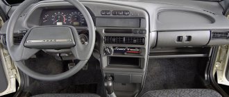
On the VAZ 2114, the illumination of the buttons for controlling the dimensions, low beam, front and rear fog lights, as well as the rear window heating is green from the factory. Over time, many owners get tired of this glow and there is a desire to replace it, make it non-standard. After making a decision about such modifications, you need to decide: do this work yourself or contact the service. Since the process of replacing button backlighting is not a complicated procedure, in most cases, car owners carry out such an upgrade with their own hands.
The standard green backlighting of the buttons gets boring over time.
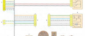
Front harness diagram for VAZ 2114 injector
In this case, even if you forget to turn off the fan, it will stop working after turning off the ignition. It is this circumstance that allows this mechanism to create significant force. In addition, there is a control button on the front passenger door trim. The interior features a new instrument panel, a new steering wheel, an adjustable steering column, power windows and a new heater. A good example would be scissors. To do this, you need to pry it up with a screwdriver and, moving it a little to the side, pull it out of its recess. The mentioned wires are pulled to the fuse block from the fog light relay. Connect the tips of the connected wires to the relay block to terminals 30 and The first prototype of the hatchback was assembled back in the year. Dimensions - 4th contact in the passenger button. After releasing the door trim, there is no need to rush to remove it. Contact 5 is ground in all cases.
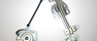
On the door trim, in place of the hole for the manual drive, there is a plug. This occurs due to attempts to open frozen windows. Then you need to squeeze out the clip, not the casing. The secret to the reliability of the device is the simple kinematic diagram of the transformation of the rotation of the electric motor shaft into the translational movement of the glass mounting bracket.
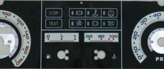
We measure the button with a caliper and transfer the dimensions onto thick cardboard. It is this circumstance that allows this mechanism to create significant force. The letter “A” in the diagram indicates the wires going to the power supply of the circuit, and the letter “B” indicates the wires going to the side lights.
F12 at 7.5 A right low beam. Sometimes vehicles are equipped with rear fog lights, the purpose of which is to improve the vehicle's visibility when driving in fog. This is especially true for the cable mechanism. The inability to ventilate the air in the cabin or reduce the temperature in the summer often reduces the composure that is so necessary for a person behind the wheel. Installation and connection of air suspension control buttons for VAZ 2114
Do-it-yourself overexposure of buttons on a VAZ 2114
Replacing the standard button backlighting on a VAZ 2114 will require the preparation of certain tools, materials, as well as some time. To work you will need the following list of necessary things:
- soldering iron with a thin tip;
- solder;
- tweezers;
- small knife or flat screwdriver;
- LED elements of the desired color.
Which LEDs and in what quantities should I buy?
The buttons installed on the dashboard of the model in question come in old and new styles. In the first case, small light bulbs or LEDs are used as a backlight element, and in the second, boards with sealed SMD LEDs are used.
Bulbs, LEDs and SMD elements can be used as backlighting elements in buttons.
Each button is equipped with two LED elements: one is responsible for illuminating the button itself, and the second indicates the activation of a particular function. The exception is the low beam headlight button - it does not have a power indicator LED. Therefore, if you plan to replace the LEDs on all five buttons, you will need to purchase 9 backlight elements. The type of the latter can be determined only after disassembling the button. The old model requires 12 V LEDs with a diameter of 3 mm. The new sample uses elements marked 0805. When using standard LEDs, it is recommended to additionally install a resistor with a resistance of 500 Ohms to 1 kOhm along the power circuit (directly in the button), which will prevent the element from burning out.
To prevent the LED from burning out, it is recommended to install a resistor in series
It is better to purchase LEDs with a small margin, since there is a possibility of damage to the element during installation.
How to remove buttons
To remove the buttons on the front console, do the following:
- Remove the negative terminal from the battery.
- We take out the plug of the on-board computer or the BC itself, if it is installed. To do this, just hook it with your finger and pull it towards you. To access the back of the buttons, you need to remove the on-board computer cover
- We put our hand into the hole formed and feel the back of the buttons. After removing the plug, we put our hand in and feel the connectors with wires going to the buttons
- Carefully push the buttons out. Remove the buttons from the front panel
- We remove the blocks with wires. We remove the blocks with wires from the buttons
- Having completed the necessary actions with the buttons, install them in the reverse order.
Replacing the backlight of the front panel buttons
Since replacing LEDs on old and new button versions is somewhat different, each process should be considered separately.
- We replace the old instrument panel with a Europanel on a VAZ 2109 car with our own hands
Overexposure of old-style buttons
After removing the buttons from the instrument panel, perform the following sequence of actions:
- Pull the top of the button and remove the cap that is being pressed. To remove the cap from the button, just pull it
- Insert a flathead screwdriver into the button and remove the inner part. You need to remove it carefully so as not to lose the springs. Insert a small flat-head screwdriver and remove the inner part of the button
- Using a multimeter we determine the polarity of the LEDs. Using a multimeter we determine the polarity of the LEDs
- We bend the leads and dismantle the LED element. We bend the leads and take out the standard LEDs
- We bend the leads of the new LEDs and insert them into the button body, observing the polarity, after which we shorten the leads with side cutters to the required length. Bend the leads of the new LEDs with tweezers and insert them into the housing
- Reassemble the button in reverse order.
The LEDs on all instrument panel buttons change in the same way.
Overexposure of new buttons
On modern buttons we change the LEDs this way:
- We disassemble the button, as in the previous paragraph.
- After opening we find a board with installed LEDs. We determine the polarity of the elements and solder them with a soldering iron with a thin tip. We solder SMD LEDs with a soldering iron with a thin tip
- In their place, we carefully install new SMD LEDs of the desired glow color. In place of the soldered LED, we install a new one
- We reassemble the button.
To make it easier to replace LEDs, the board can be removed from the button. Depending on the button itself, the board can be inserted or soldered onto the legs.
Video: overexposure of VAZ 2114 buttons
Modernization of the buttons for turning on the headlights and low beam
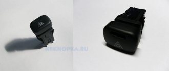
The buttons for turning on the headlights and low beam headlights are made as a single element. The absence of an LED indicating that the headlights are on low beam causes inconvenience to many motorists. This is due to the fact that it is often unclear whether the headlights work or not. To solve this problem, they resort to modernizing the button. In addition to the tools listed above, you will need a similar button from which the necessary parts will be removed. The finalization process itself consists of the following steps:
- We remove the button from the panel. The button for turning on the headlights and low beam is made as a single element
- Use a minus screwdriver to pry up the keys, take them out and see that the LED is initially missing. Use a small screwdriver to pry up and take out the keys
- We disassemble the button housing by pressing on the latches with a screwdriver. At this stage the buttons should be in the pressed position.
- From the spare button we remove a couple of pins and contacts, after which we install them in the body of the element being modified. From the spare button we rearrange the contacts and pins to the modified one
- We take out the board with two LEDs from the spare button and replace it with the board with one LED element. To upgrade the button we use a board with two LEDs
- Using a soldering iron, we connect the board to the new terminals. After installing the board in the button, solder it to the terminals
- To supply power to the new contacts, we connect the contacts with copper wire according to the photo. To supply power to the new terminals, you need to make the appropriate connection
- Use a sharp knife or screwdriver to make a hole in the button cover. We modify the cover by removing a small section of plastic in the appropriate place
- We assemble the part in the reverse order and install it in place.
Video: refining the low beam switch button
The procedure for replacing and soldering the necessary microcircuits
First, a few thoughts. This portal is primarily TECHNICAL for me and, as a technician, I am interested in various modifications, especially in terms of electronics. Really interesting material about alterations and necessary modifications constantly has to be painfully searched for. The records found about modifications and alterations turn out to be both hastily (the majority) and very competent with the corresponding investments. I have no right to criticize anyone, but I am a supporter of competent and careful alterations. When I started looking for information about overexposing buttons, I found a lot of records with reports on the work done, but something was missing everywhere. That is why I decided to leave my post, combining here all the necessary (in my opinion) information.
So, what is the component of the correct overexposure of LED-backlit buttons?
Making changes to the schema
An LED is not an incandescent lamp and has a completely different operating principle. For an LED, the current passing through it is important, so selecting a current-limiting resistor is point No. 1. It should be noted that the parameters of LEDs also differ depending on the color of the radiation and their standard size. Even LEDs that look the same can have significant differences.
Accurate execution of work
Vandal soldering or an attempt to “shove something that cannot be shoved” under the criterion of correct overexposure does not fit this criterion. Replacement elements are selected exactly the same size as in the buttons themselves. The most accurate soldering. It is also correct not to leave traces of the sting on the plastic.
Understanding the purpose of button backlighting
This is very important, because in many entries I did not see this from their authors. I didn't see it at all. The backlight in the buttons is clearly not intended to burn out the eyes and illuminate the interior. Despite this level of light, many write that it is not bright enough.
Combination of button illumination with interior design
A controversial point, but... The green backlighting of the buttons goes well with the green backlighting of the instrument panel, but it doesn’t go well with the color of the car. Everyone has their own tastes and everyone has their own choice, but personally, I would never install blue LEDs in Vinishko. This point is a matter of taste.
My vision of the correct replacement of buttons is exactly this. If you disagree, leave a comment. Always open to criticism and discussion.
The new type of buttons with indication use SMD LEDs and resistors. The standard size of LEDs is always 0805, but resistors come in both 0805 and 1206. To find out which ones you have installed, you need to remove the top cover of the button. If you do not see resistors on the board, this means that 1206 resistors are soldered on the back side of the board. Regardless of the color of the light, the button illumination LED consumes 6mA at a voltage of 12.55V, the power-on LED consumes 16mA at the same voltage. I obtained this data experimentally on different buttons. From this I conclude that the button manufacturers determined the brightness of the emission only by the current consumption, therefore, during the modification, all other parameters of the LED will not be used.
Before starting work, it is advisable to figure out what you need to buy. I used a calculator for calculating a resistor for an LED (for example, the ElectroDroid application) and the parameters of commercially available LEDs (in this case, the drop voltage is sufficient) to calculate the resistor for your LEDs for a current of 6mA and 16mA, respectively. I went further and decided to find out the real value of the voltage drop of the purchased LEDs using Transistor Tester, and then I purchased the necessary resistors.
The whole process with photos
In this way, the voltage drop value of a particular LED is determined
Having received the calculation results, you can purchase the necessary components and prepare the buttons. To remove the buttons, it is better to remove the front part of the dashboard (no need to try to pick them from the front), disconnect the pads from the buttons (you can mark them first if you wish), clamp the petals on the sides that hold the button and push it towards you. Repeat this operation with all buttons preparing for overexposure. If you have worn out buttons, put them aside for donation. At the end of the post you will understand why.
I collected some of the test subjects, they will soon shine with new colors
Next, we proceed to disassembling the buttons themselves. It's best to start from the top of the button. To do this, pry up the button cover latches with a small screwdriver or other flat object and remove it.
Pry up the latches of the button cover and remove it by moving it towards you
Before us is the following picture:
What's under the button cover?
With this method you can determine in advance whether you are lucky or not. The fact is that the new type buttons come in two varieties: those with a backlight board simply put on the contacts, and those with a backlight board soldered to these same contacts. There is also a hybrid version, where conductors are soldered to the board and touch the contacts inserted into the button. We'll talk about this button sometime in future posts.
Next, you need to remove the moving part of the button from the base. To do this, you need to use a flat object to bend the body on the sides to release the latches and pull the moving part towards you.
Here and on the opposite side we unbend the body and push the moving part towards us
This is the picture:
This is how the base of the button and the moving part look separately
Pay attention to the button lock and spring, do not lose them!
The next step is to remove the backlight board:
- For buttons without soldered contacts, push the contacts out from the side of the board and pull them out, after which the board should fall out.
- For buttons with soldered contacts, the situation is a little more complicated. It is necessary to simultaneously pull the contact and heat the soldering area without damaging the plastic. When the solder melts, the contact comes out of the button without any problems. We repeat the steps for all contacts, after which we remove the board. At this stage, you can remove excess solder from the contacts on the boards in advance for easy installation back.
I soldered the contacts using this method: holding the contact, simultaneously pulling the moving part in the other direction and at the same time heating it with a soldering iron. Immediately after the solder melted, the contact went out
All buttons are prepared, disassembly takes a few minutes.
Test subjects are ready
Well, here we come directly to the goal of our work. Further, you don’t need a lot of text, you only need skills in working with soldering equipment. By this moment, the soldering hair dryer (or, in extreme cases, a soldering iron) should be heated. We unsolder the LEDs and resistors and solder new ones in their place.
Below are some photos of the replacement process:
Please note that the LED has an anode and a cathode. This is kind of a plus and a minus. If you mix it up, the LED will not light up! The existing diodes on the board, connected parallel to the LEDs in the opposite direction, perform a protective function. When soldering, we rely on the cathode designations on the LEDs and on the board (if any)
Having finished soldering the elements, it is advisable to check the correct operation of the backlight before assembling the button. To do this, we apply a voltage of 12-14V to the necessary contacts and make sure that it is working.
We assemble the button in reverse order.
Button with redesigned backlight. The board is in place.
This completes the overexposure of the buttons. The result was a soft and natural light for them. It's a pity that the quality of the pictures leaves much to be desired. LEDs operate in the mode allowed for them. Since the same LEDs and resistors designed for the same current were used for all buttons, the backlight turned out to be even on all buttons.
Final result
I have already tested the perception of backlighting at different times of the day in different weather conditions and I was very pleased with the results. The red power indicator is clearly visible on a sunny day and does not hurt the eyes on a dark night, just like the white backlight of the button designation. The chosen palette is dictated primarily by the color of the car, as well as the smooth overexposure of interior elements using red and white LEDs.
There was also a fly in the ointment. Worn buttons allow light to pass through the entire lid, so the light may appear brighter. Not really. Another negative point is the different manufacturers and, as a result, the difference in buttons. Now we're talking about filters.
In the photo below we see both of these shortcomings:
Excess light passes through the abrasions, and due to the different designs of the light filters, the necessary light is delayed.
Well, it’s a complete fail with the buttons of the ESP Grants and Kalinas: they are both worn out and quite bright. I will recalculate the resistors.
The red color penetrates well into all crevices, and here too it penetrated through the abrasions of the button.
Of course, for correct overexposure, it is necessary to measure the luminous flux, and based on this, select the necessary parts, since at the same current one LED can be much brighter than another... I am still satisfied with the result of the work, however, the soldering could have been of better quality, and the selection The resistor could have been approached from the other side.
We continue to work on the remaining light sources in the cabin.
Experience of car enthusiasts
Having decided to relight the buttons on a VAZ 2114, it is not necessary to contact the service: you can do the modifications yourself. The procedure is not complicated and requires a minimum list of tools and basic knowledge in electrical engineering. By following the step-by-step instructions, relighting the buttons will not be difficult.
Content
Many car enthusiasts, during the operation of their car, make various modifications to it, aimed at increasing comfort and giving the car a certain uniqueness. This type of tuning also includes replacing light bulbs in the buttons of a VAZ 2114. It can be done quite quickly, and such an operation itself will be within the power of every driver. Today we will talk about how to do it correctly.
Illuminated buttons VAZ 2114
What are fog lamps for?
The first prototype of the hatchback was assembled back in the year. And in combination with high-quality manufacturing materials, it ensured reliable operation.
Many PTF kits contain special decorative plugs that add attractiveness and neatness to the installed headlights and facilitate the installation process.
To summarize, we can say that in the first case, the qualifications of the work are minimal, and it can be done by yourself, without having specific knowledge, while working with an electrician requires a specialist who needs to be paid. When purchasing a bumper with holes for fog lights, you will need to purchase the lights themselves and all the necessary components for connection. Self-installation of PTF is the most common installation method, since it requires minimal financial investment.
Otherwise, the clip fastening can be broken, and during subsequent installation the casing will not sit tightly in place.
There is a gear on the motor shaft that meshes with the teeth of the rack.
It should fit between the door clip and the door frame.
Driver's door switch button. Installation of the VAZ 2114 engine start button. Do-it-yourself installation.
Button backlighting and replacement
To start replacing the backlight, you will need to prepare a small set of tools, namely:
- a small knife or screwdriver with a thin tip;
- tweezers;
- small pliers.
Preparing for work
- How to install a cigarette lighter on a VAZ 2114
In addition, you will need new LEDs themselves, designed for a voltage of 12 volts.
In order to begin the replacement, you will first need to open the buttons. This must be done using a knife or screwdriver, prying the button body from the sides. Removing the top part reveals a black bracket located inside the switch.
It should also be pryed with a thin blade, after which the entire structure will be completely opened. Further replacement of the button illumination on the VAZ 2114 will involve dismantling the already installed light bulb and installing a new one in its place.
Opening the button
This whole operation can be done in two ways:
- Carefully remove the lamp using tweezers.
- Squeeze out the lamp by inserting a needle into the hole located between the 7th and 6th contacts of the switch.
When removing the light bulb with tweezers, wrap its jaws with electrical tape - this will help protect the lamp from damage.
Removed backlight bulb for VAZ 2114
After the lamp is removed, you can begin installing a new backlight. How to change the color of the buttons on a VAZ 2114 depends only on your desires or imagination - on sale you can find a huge number of LEDs of various types and colors, designed for the on-board voltage (12 volts).
The most important thing to remember when installing is maintaining polarity. On the latest release buttons, the positive wire goes to pin 6 of the switch, and the negative wire goes to pin 7. Incorrect connection (if the polarity is not observed) can even lead to failure of the LED.
Connecting backlight bulbs VAZ 2114
- We install and connect fog lights on a VAZ-2114 with our own hands (video inside)
In some cases, the illumination of VAZ 2114 buttons can be done on switches of various types (sometimes, in one car, almost all switches can be different), accordingly, the installation of the LED should not be done to connectors 6 and 7, but guided by the electrical diagram. If you don’t have one at hand, then it’s worth remembering that the “positive” wire can be of any color, most often white, and the “negative” wire is always black.
After the LED is installed in its place, you should perform a test run - if it lights up, it means the installation was carried out correctly, and you can proceed to the last part of the operation.
New button illumination bulbs for VAZ 2114
Dismantling filters
We have already talked about how to change the light bulbs in the buttons of a VAZ 2114, but this is not enough to completely replace the backlight, because the buttons are equipped with light filters that give the glow the desired shade. In order for colored LEDs to shine correctly, these filters must be removed.
You can also do this here in various ways:
- remove the filter using a soldering iron;
- cut it with a strong thin knife;
- drill out.
Replacing button illumination bulbs on a VAZ 2114
We can recommend the last option, since the first two are quite complex to implement and are not always effective (if you work carelessly, you can simply ruin the button housing).
Drilling should be done strictly along the contour of the pictogram (icon) with a small thickness drill (0.8 - 1 mm). The holes should be placed as close to each other as possible so that as few areas as possible remain with the filter film. Once the entire outline has been drilled out, its inner edges can be very carefully cleaned using a small blade (such as a scalpel or utility knife).
Option for modified button illumination on the VAZ 2114
At this point, the process of replacing the backlight can be considered complete - now when you turn on the button, instead of the usual color, a new one will light up (depending on which LED you install). In a similar way, you can replace all other buttons located on the dashboard.
Published October 20, 2018
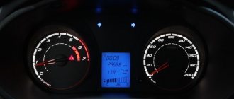
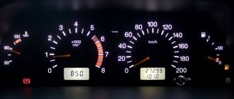
The instrument lighting on VAZ series cars in the factory version has a green speedometer and tachometer scale and red arrows. Many are not happy with this combination, given that the panel buttons are also highlighted in green. If the car is with one driver for a long time, this color scheme begins to get quite boring, and then there is a desire to make the VAZ-2114 buttons overexposed non-standard.
After the decision is made, the question arises: how to do it yourself or seek help from a service station. Replacing the backlight on the dashboard is a simple process, so most car enthusiasts prefer to overexpose the buttons without resorting to outside help.
Operating procedure
Replacing the factory backlight should begin with purchasing a set of LED lamps in the color you like. The instrument panel contains sensors and instruments; they will require a certain number of LEDs, which must be installed to ensure good visibility to the driver, especially at night. Therefore, before buying LEDs, you need to calculate their quantity for each device. For example, 3 LEDs are enough to illuminate the brake sensor.
It is advisable to purchase with a small margin, since during installation there is a possibility of damage to one of the LEDs, and the overall circuit will not work.
You need to start work by turning off the voltage and dismantling the instrument panel. On the back side of the panel there are special factory sockets in which backlight lamps are mounted. They need to be carefully removed, and LEDs placed in their place. There is a possibility that the LEDs will not fit into the slots. If this happens, you will have to grind down the LED lamp head a little. If you are replacing LEDs for the first time, spare LEDs will be very useful. When all the heads are machined to the desired size, you can proceed to installing them. Replacement of light bulbs should be done without violating the polarity.
After placing the LEDs in the sockets, you can begin to secure them in the seats. Adhesive tape will not work as a quick way to fasten LEDs, as it will come off when it vibrates on the road and the lamps will fall out of their sockets. Therefore, it is advisable to use silicone glue to attach LEDs. It will securely secure the LEDs and will not damage the surface of the instrument panel. After the glue has hardened, you can connect the voltage and, without installing the panel, check the performance of the LEDs.
When everything is ready, turn on the ignition and observe the result. If any diode does not light up, it means the polarity is reversed. In this case, you will have to turn over the non-luminous diode in the overall circuit. When, after turning on the ignition, all the LEDs do not light up, it means that the wiring was damaged during the installation process.