Additional functions
The display also displays other parameters of the Lada Vesta, which greatly facilitate driving not only for beginners, but also for experienced drivers. For example, data from parking sensors ensures easy parking of a car by generating light and sound signals. On-board computers are provided on the entire Lada vesta sw cross line, station wagons and other luxury models. The operation of standard electronic devices is ideally complemented by additional equipment; its installation is carried out at service stations or with your own hands. For example, the standard cruise control of the Lada Vesta successfully interacts with the additional onboard onboarder. Modern onboarder models have advanced functions: they are integrated with a satellite navigation system, equipped with an Internet connection and TV.
Description of functions
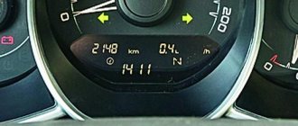
A review of the Lada Vesta on-board computer shows which parameters are displayed on the display or front panel display. This makes the life of a Lada car enthusiast much easier. On Vesta, the standard on-board computer shows the following information, in addition to error codes:
- The magnitude of the vehicle network voltage;
- Cruising range on fuel in the gas tank;
- Current and average fuel consumption;
- Remaining fuel in the tank;
- Travel time along a specific route;
- Average speed;
- Watch;
- Total mileage;
- Controls the outside air temperature;
- Gives gear shift hints (with or without sound);
- On a Lada with cruise control, information about the installed parameters is displayed;
- If there is an AMT, the gear engaged or the auto - manual mode is displayed.
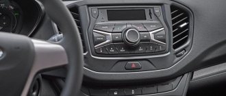
On-board computer Lada Vesta The on-board computer on the Lada Vesta is configured using two keys on the right steering column switch. Using the keys, entering the menu, you can control the readings of Vesta BC, displaying the necessary data on the control panel. Thus, the driver constantly has the opportunity to control the required parameters of Vesta.
Settings
After reading the operating instructions, operating the on-board computer will not seem difficult. In order to set or manage parameters, press the up key and hold for a while. We get to the settings menu, where you can:
- Set time;
- Reset previous mileage;
- Reset average flow and average speed.
Setting the clock
Some car owners have a question about how to set the clock. For this:
- Press the top key (hold it for about 3 seconds) to enter the editing mode.
- The previously set time is displayed on the screen.
- Again holding the top button for about 2 seconds.
- The first value, the clock, starts blinking. Use the arrows to set the required value.
- Hold up again and go to setting the minutes.
- After the time has been set, it is necessary to secure the readings. To do this, you again need to hold the up key for a long time.
The time setting is complete.
Replacing the fuse box for Lada Vesta SV Cross
Necessary tools, materials:
- rags;
- additional lighting as needed;
- a set of new relays;
- plastic clips in the amount of 3 - 5 pieces, in case the standard ones are damaged.
Sequence of actions when replacing the power supply in the engine compartment:
- The car is installed within the perimeter of the repair area, the hood is open, and the parking brake is depressed.
- Behind the battery, closer to the air filter housing, a module with fuses is installed. We unclip the side latches and remove the relay with the serial number we need.
- We troubleshoot the power supply, clean the internal contents from dust and dirt.
- We install a new “relay” and assemble the structure in the reverse order.
Algorithm of actions when replacing inside the car:
- We turn off the engine and lock the parking brake.
- In the lower left part of the dashboard, behind the steering rack, we find the power supply cover, snap off the four plastic clips.
- We remove the cover, unscrew the three latches, and lift the power supply towards you.
- We inspect the module, replace non-working “relays” with new ones, and assemble the structure in the reverse order.
Signs of faulty fuses
| Malfunction | Cause | Elimination |
| The lights don't come on | Oxidation of contacts | Cleaning/stripping terminals |
| Fan, washer, and cleaner do not work | Damage to electrical wiring, relay | Diagnostics, replacement with a new one |
| Windshield wiper does not work | There is no current in the voltage circuit, the fuse is faulty | Checking wiring integrity, replacing power supply |
| The hazard warning lights and turn signal repeaters turn on | Checking the functionality of the power supply | Replacing faulty elements |
| The tachometer needle works chaotically, data transmission is unstable | Damage to the integrity of electrical wiring | Replacing faulty elements |
| The engine fan is not active, even during forced activation | Circuit continuity check | Replacing damaged wiring sections |
Where is the LADA VESTA ECU located?
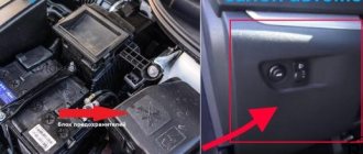
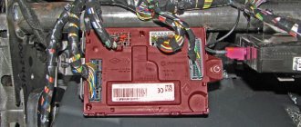
The ECU on the Vesta is located in the engine compartment (engine compartment). The control housing is rigidly fixed to the vehicle frame. The wiring harness approaches the device from below and is connected through a block with latches. Due to its location under the hood, the VESTA ECU can become a target for thieves who replace the device with another. The method of protecting the unit from intruders is an additional housing made of 3 mm steel with stud fastening to the frame.
The connection between the ECU and the CBKE, which is located under the dashboard to the right of the driver, in the Lada Vesta is made through a connector with 16 contacts - OBD2. The block is located in the cabin to the left of the driver's seat under the panel, near the hood lock handle. The OBD2 contact connector is an open type.
Photo source: https://www.drive2.ru/l/551817399263822806/
Diagnostics and error reset are carried out through this device using ELM327. The control unit is removed in order to flash new software using a bootloader in BLS mode.
OBD 2 pinout
Brands and years:
Gasoline passenger cars and light commercial vehicles manufactured or imported into the United States since 1996 (US CARB and EPA legislation) and in Europe (EOBD) since 2000-2001 (European Union Directive 98/69EG) and Asia (mainly since 1998). ).
Conclusions and their purpose:
| № | Color | Purpose |
| 2 | J1850 Bus + | |
| 4 | Body grounding | |
| 5 | Signal Ground | |
| 6 | Line CAN-High, J-2284 | |
| 7 | K-line diagnostics (ISO 9141-2 and ISO/DIS 14230-4) | |
| 10 | J1850 Bus- | |
| 14 | Line CAN-Low, J-2284 | |
| 15 | L-line diagnostics (ISO 9141-2 and ISO/DIS 14230-4) | |
| 16 | Power supply +12V from battery |
Diagnostic connector pins for used protocols
Pins 4, 5, 7, 15, 16 - ISO 9141-2.
Pins 2, 4, 5, 10, 16 - J1850 PWM.
Pins 2, 4, 5, 16 (without 10) - J1850 VPW.
The ISO 9141-2 protocol is identified by the presence of pin 7 and the absence of pins 2 and/or 10 on the diagnostic connector.
If pin 7 is missing, the system uses the SAE J1850 VPW (Variable Pulse Width Modulation) or SAE J1850 PWM (Pulse Width Modulation) protocol.
All three data exchange protocols operate via a standard OBD-II J1962 connector cable.
On-board computer control algorithm
1. Selection of on-board computer functions (carried out using the keys on the right steering column switch).
2. Selecting trip meters and switching between clock and temperature.
3. Enter parameter setting mode, select parameter.
3.1. Setting the time.
When you exit the time setting mode, the seconds counter is reset to zero (reset without rounding). If there are no button presses within 60 seconds, the time setting mode will exit automatically.
4. Display mode of parameters of the “Cruise control” or “Speed limiter” functions.
In the mode of displaying the parameters of the “Cruise control” or “Speed limiter” functions, it is possible to switch the displayed function of the on-board computer (point 1) and the total and daily mileage counters (point 2), the indication of outside air temperature and time is not available, parameter setting modes (point 3 ) are not available.
- “short” – press for less than 1.5 seconds, triggered when released.
- “long” – press for more than 1.5 seconds, triggered by time.
- yellow color – the segment is blinking (square wave, 1 Hz).
- When resetting the route parameters (clause 3(d)), the following parameters are reset to zero: average fuel consumption, fuel consumed, travel time, average speed.
Bookmaker settings are also shown in the video:
To change the sound of the turn signals, you need to go to the secret menu (it does not work on the instrument cluster). To do this, press two BC buttons at the same time. More detailed instructions in the video:
Are you satisfied with the functions of the Lada Vesta on-board computer? Let us remind you that other operating instructions for this vehicle can be found in this section.
It is difficult to imagine a modern car without an on-board computer (alternative names: “BC”, “carputer”, “onborder”), which allows you to increase engine efficiency, reduce gasoline consumption, optimize the operation of the gas distribution system and synchronize the interaction of all units. In addition to the above, BC reduces the concentration of harmful emissions. The onborder performs the functions of cruise control, climate control, and displays the information necessary for the driver, allowing him to make the right decisions on transport management and optimal movement along the chosen route. That is why all modern Lada Vesta models are equipped with BCs that successfully perform the functions assigned to them.
Description of functions
A review of the Lada Vesta on-board computer shows which parameters are displayed on the display or front panel display. This makes the life of a Lada car enthusiast much easier. On Vesta, the standard on-board computer shows the following information, in addition to error codes:
- The magnitude of the vehicle network voltage;
- Cruising range on fuel in the gas tank;
- Current and average fuel consumption;
- Remaining fuel in the tank;
- Travel time along a specific route;
- Average speed;
- Watch;
- Total mileage;
- Controls the outside air temperature;
- Gives gear shift hints (with or without sound);
- On a Lada with cruise control, information about the installed parameters is displayed;
- If there is an AMT, the gear engaged or the auto - manual mode is displayed.
On-board computer Lada Vesta The on-board computer on the Lada Vesta is configured using two keys on the right steering column switch. Using the keys, entering the menu, you can control the readings of Vesta BC, displaying the necessary data on the control panel. Thus, the driver constantly has the opportunity to control the required parameters of Vesta.
Settings
After reading the operating instructions, operating the on-board computer will not seem difficult. In order to set or manage parameters, press the up key and hold for a while. We get to the settings menu, where you can:
- Set time;
- Reset previous mileage;
- Reset average flow and average speed.
Setting the clock
Some car owners have a question about how to set the clock. For this:
- Press the top key (hold it for about 3 seconds) to enter the editing mode.
- The previously set time is displayed on the screen.
- Again holding the top button for about 2 seconds.
- The first value, the clock, starts blinking. Use the arrows to set the required value.
- Hold up again and go to setting the minutes.
- After the time has been set, it is necessary to secure the readings. To do this, you again need to hold the up key for a long time.
The time setting is complete.
Secret menu of BC Lada Vesta + Christmas Tree Test of the Salon!
Problems when paying with bank cards
Sometimes difficulties may arise when paying with Visa/MasterCard bank cards. The most common of them:
- There is a restriction on the card for paying for online purchases
- A plastic card is not intended for making payments online.
- The plastic card is not activated for making payments online.
- There are not enough funds on the plastic card.
In order to solve these problems, you need to call or write to the technical support of the bank where you are served. Bank specialists will help you resolve them and make payments.
That's basically it. The entire process of paying for a book in PDF format on car repair on our website takes 1-2 minutes.
If you still have any questions, you can ask them using the feedback form, or write us an email at
Lada Vesta fuse box with description (interior)
This mounting block is located in a place familiar to drivers - near the left foot. Actually, the space around the trunk opening button and the headlight adjustment control is the cover of the mounting block.
First, remove the plastic clips (nails) that secure the cover to the upholstery. One of them is located on the side of the ignition switch, the other is in the lower left part of the cover (may be absent on some cars). Next, turn the 3 plastic handles at the bottom and pull the lid, releasing all the holders.
Schematic layout
In the interior mounting block you will see the following picture:
Interior mounting block
Schematically the block looks like this:
Schematic location of fuses It is deciphered as follows: Decoding of spare fuses Decoding of spare fuses Decoding of spare fuses Decoding of spare fuses Decoding of spare fuses Relays that are present in the cabin: Designations of the snout in the cabin
Body connector
Layout of buttons on the steering wheel
Lada Vesta fuse box with description (engine compartment
The required box is located above the battery, on the right side of the air filter. On the cover of the unit you can see warning signs in the form of a crossed out figure of a man with a hose and a lightning bolt.
To remove the cover, bend the two latches at the top and bottom. Be careful because... they are very fragile.
Schematic layout
The contents of this mounting block are as follows:
Mounting block
The current limit (amps) is indicated on each component. The Lada Vesta fuse diagram under the hood looks like this:
Lada Vesta fuse diagram
Which circuit each fuse belongs to and which consumer it is responsible for can be found in the table below.
Fuse Circuit Chart Fuse Chart Note: Depending on the configuration, some items may be missing.
Table with the designations of the relays that are present in the engine compartment block:
Relay designation table
Fuse table for Lada Vesta SV Cross
Fuse diagram
| № | Denomination | Chain | Purpose | Type |
| 1 | 15A | K15R | Power supply for the right steering column switch (washer) | mini |
| 2 | 30A/5A | K15R | Left steering column switch (not lux/lux) | mini |
| 3 | 10A | Left high beam headlight, (not luxury) | mini | |
| 4 | 30A/5A | K30S | Left steering column switch (not lux/lux) | mini |
| 5 | 15A | K15R | Seat heating | mini |
| 6 | 7.5A | K30S | Side lights on the starboard side | mini |
| 7 | 10A | K30S | Left side marker lights | mini |
| 8 | 5A | K30S | Rear fog lights | mini |
| 9 | BEHIND | Right turn signal in the mirror | mini | |
| 10 | 5A | K15S | AMT robotic gearbox selector | mini |
| 11 | 10A | Left low beam headlight (not lux) | mini | |
| 12 | 15A | K30S | BCM controller (direction indicators) | mini |
| 13 | 10A | K30S | VSM controller (own power supply) | mini |
| 14 | 10A | K30S | Turning off the brake pedal | mini |
| 15 | 5A | VTR | Power supply for rain and light sensor, headlight range control | mini |
| 16 | 5A | VTR | Turning off the brake pedal | mini |
| 17 | 5A | VTR | Lighting for the glove compartment, trunk, sills | mini |
| 18 | BEHIND | Left turn signal in the mirror | mini | |
| 19 | 10A | Right low beam headlight (not lux) | mini | |
| 20 | 5A | Heated exterior mirrors | mini | |
| 21 | 15A | K15S | Airbag system control unit | mini |
| 22 | 5A | K15S | Instrument cluster | mini |
| 23 | 5A | K30S | Instrument cluster | mini |
| 24 | 5A | ACC | ERA GLONASS, radio | mini |
| 25 | 5A | VTR | ESP 9.1 controller | mini |
| 26 | 15A | K30S | Power supply to fuel pump module | mini |
| 27 | 5A | K15S | Power supply for parking sensors | mini |
| 28 | 5A | K15S | Electric Power Steering Controller | mini |
| 29 | 10A | K30S | Power supply for trailer lighting | mini |
| 30 | 5A | K15S | ERA GLONASS controller | mini |
| 31 | 5A | K30S | ERA GLONASS controller | mini |
| 32 | 10A | K15S | Power supply for K15M bus (engine compartment) | mini |
| 33 | 5A | VTR | Window control | mini |
| 34 | 5A | VTR | Power supply for steering angle sensor, steering wheel button block | mini |
| 35 | 5A | VTR | Driver's door switch block | mini |
| 36 | 15A | K30S | Radio, diagnostic connector | mini |
| 37 | 7.5A | K30S | Right brake light | mini |
| 38 | 7.5A | K30S | Left brake light | mini |
| 39 | 10A | K15R | Daytime running lights (not luxury) | mini |
| 40 | 10A | K15R | Right high beam headlight (not luxury) | mini |
| 41 | 20A | ACC | 12V socket (power supply for additional devices), cigarette lighter | JCase |
| 42 | 20A | K30S | VSM controller (VTR bus power supply) | JCase |
| 43 | 20A | K30S | BCM controller (door locks) | JCase |
| 44 | 30A | K30S | Window lifters | JCase |
| 45 | 30A | K30S | Interior heater fan | JCase |
| 46 | 30A | K15R | Power supply for the right steering column switch (windshield wiper) | JCase |
| 47 | 25A | K30S | EMM controller (PDS, LBS, LGO) | auto |
| 48 | 30A | K30S | EMM controller (windshield wiper) | auto |
| 49 | 25A | K30S | EMM controller (PTF, ZPTO, license plate) | auto |
| 50 | 25A | K30S | EMM controller (LDS, PBS, PGO) | auto |
| Relay | Denomination | Chain | Purpose | |
| K1 | 70/50A | K15R | Power supply for lighting and seat heating (not luxury/luxury) | |
| K2 | 30A | Free | ||
| K3 | 30A | Heated rear window | ||
| K4 | 30A | Front windows | ||
| K5 | 40A | Interior heater fan | ||
| K6 | 30A | Rear window lifter | ||
| K7 | 20A | Fuel pump module | ||
| K8 | 20A | ACC (12V socket power supply) |
| № | Denomination | Chain | Purpose | Type |
| 60 | 70A | K30M | EURU | maxi |
| 61 | 30A | K30M | Heated rear window | maxi |
| 62 | 40A | K30M | ESP | maxi |
| 63 | 15A | K30M | Air conditioner clutch | auto |
| 64 | ||||
| 65 | 25A | K30M | ESP | auto |
| 66 | 5A | K15M | AMT controller | mini |
| 67 | ||||
| 68 | 70A | K30M | AMT controller | maxi |
| 69 | 15A | Controlling the A/C clutch relay and relay box | auto | |
| 70 | 60A | K30M | K30S | maxi |
| 71 | 60A | battery | maxi | |
| 72 | 60A | battery | maxi | |
| 73 | 10A | K30M | Sound signal | mini |
| 74 | 5A | K15M | Reversing light switch | mini |
| 75 | 60A | K30M | Heated windshield | maxi |
| 76 | 10A | K30M | Alarm horn relay | mini |
| 77 | ||||
| 78 | 10A | Power supply for oxygen sensors, canister purge valve, timing valve | maxi mini | |
| 79 | 40A | K30M | Cooling Fan Relay/Relay Box | maxi |
| 80 | 5A | K15M | Heated windshield relay coil | mini |
| Relay | Denomination | Purpose | ||
| K21 | 30A | Heated windshield relay 1 | ||
| K22 | 30A | Heated windshield relay 2 | ||
| K23 | 30A | Starter relay | ||
| K24 | 20A | Horn relay | ||
| K25 | 20A | Alarm horn relay | ||
| K26 | ||||
| K27 | 20A | Main relay KSUD | ||
| K28 | 20A | A/C compressor clutch relay | ||
| K29 | 40A | Cooling fan relay |
Purpose and description
The central body electronics unit (CBEC) came from Renault and is located under the panel behind the glove box. The block is designed to perform the following functions:
Review of the popular car Lada vesta: sport wagon cross
_x000D_
- _x000D_
- Access control system functions; _x000D_
- Starter control; _x000D_
- Control of relays of additional consumers; _x000D_
- Control of the rear window heater and electric side mirror heaters; _x000D_
- Windshield defroster control; _x000D_
- Control of direction indicator and hazard warning lamps; _x000D_
- Interior lighting control; _x000D_
- Control of door sill lamps (for the “Lux” package); _x000D_
- Trunk lighting control; _x000D_
- Windshield wiper control (for “Classic” and “Comfort” trim levels); _x000D_
- Energy saving control of vehicle interior lighting devices; _x000D_
- Monitoring the state of the brake signal switch (BST); _x000D_
- Monitoring the state of the clutch pedal position signal switch (CPPS) (for configurations with a manual transmission); _x000D_
- Indication. _x000D_
_x000D_
Lada Vesta wiring diagram
A general wiring diagram is too cumbersome and difficult to understand, so diagrams are used to show the individual connections.
Please note that each diagram contains performance tables that indicate the designation of the harness in question depending on the vehicle’s configuration. The given wiring diagram of Lada Vesta is black and white, and the colors of the wires are indicated by letters
The decoding is in this table:
The Lada Vesta wiring diagram shown is black and white, and the colors of the wires are indicated by letters. The decoding is in this table:
Wire colors
Front wiring harness
Shows the location of the following elements:
- headlights;
- sound signals;
- cooling system fan;
- sensors (wheel speed, air temperature, hood position, etc.);
- engine control units and ABS;
- canister purge valve;
- alarm switch;
- windshield wiper drive;
- windshield heating element;
Rear wiring harness
Displays the location of devices such as:
- additional body electronics units;
- sensors (rain, cabin air, wheel speed);
- interior lighting control unit;
- fuel tank.
Front doors
The connection of the following elements of the Lada Vesta is described:
- locks;
- lampshades;
- window regulators and their switches;
- speakers;
- mirror drives.
There are also switch blocks in the left door of Vesta.
Ignition system
This harness connects all devices related to the operation of the ignition on the Lada Vesta:
- sensors;
- motor control controller;
- battery;
- generator;
- circuit breakers;
- timing control valve;
- reverse light switch.
Dashboard
The Vesta dashboard, as the most “stuffed” place, has a corresponding electrical circuit. This includes:
- sensors (steering angle, clutch pedal position);
- various relays (socket, fuel pump, heater fan, exterior lighting, power windows);
- various switches and switches;
- diagnostic connector;
- steering wheel keys;
- cigarette lighter;
- airbags;
- control units.
And a number of other electronic little things that can be listed endlessly.
Additional rear wiring harness
This Lada Vesta wiring diagram contains the following:
- parking sensor control unit;
- trunk lid lock drive;
- room lighting;
- trunk lighting;
- lights on the body and trunk lid;
- heated rear window.
Additional right rear wiring harness
This harness connects the following devices:
- sensors (side impacts, seat belts, passenger presence);
- airbag control;
- ATM and manual transmission switch;
- robotic gearbox selector.
Robotic gearbox
The connection of the control elements of the “robot” is shown:
- actuators of the clutch engagement mechanism, gear selection and gear shifting;
- input shaft speed sensor.
Additional Lada Vesta body electronics unit and LEDs
We all know very well how quickly the Lada Vesta was created, because the hype around this model was serious. On the other hand, all this resulted in the use of not entirely successful design solutions, which subsequently began to appear on production vehicles. One feature concerns the additional body electronics unit of the Lada Vesta.
Background
This situation arose with one of the Drive members, who is known there under the nickname Schoolboy11, with his Lada Vesta Red Menace car.
After purchasing Vesta, he decided to replace the size lamps with two-pin LEDs. He approached the choice of diodes responsibly - he purchased high-quality, proven products that were selected by professionals. Naturally, with them the exterior of the sedan was completely transformed.
Vesta looks much cooler with LEDs!
Problem
However, difficulties began very soon. One “fine” day, the dimensions on his car burned out, everywhere. Naturally, he tried to install standard lamps, but this did not help. As you know, in such situations everything is usually limited to replacing the fuses for the left and right side lights, which in Vesta’s manual are indicated by the symbols F16 and F17.
However, if you remove the cover that covers the fuses, the owners will find one very unpleasant surprise - fuses F16 and F17 are not there. There are not even contacts - just technological holes.
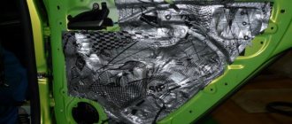
The cover that covers the fuses.
Separately, it is worth mentioning the lid itself. It is made the same as on Grant - from hard plastic. Moreover, plastic clips do not look very reliable and, as practice shows, they break quickly. On the other hand, the lid is equipped with a foam insert that serves as sound insulation.
Solution
If such a problem happens to you, it is recommended to contact the Lada dealership. In this case, you should not count on warranty service, since in this case there is no fault of the plant.
The thing is that the resistance of the diodes is greater than that of standard lamps, which is why the electronics unit burns out. In this case, there is a reckless decision by AvtoVAZ designers, who abandoned fuses and installed an electronic unit from the Renault Trafic model in Vesta.
Vesta’s design uses this electronics unit.
To restore the operation of the electrics, it is necessary to replace the additional body electronics unit of the Lada Vesta.
Where can I buy?
You can buy it at a dealership, but in the showroom it is usually very expensive. As an alternative site, you can use the resources presented in the table below. However, it is worth considering that prices may vary, and the part is not always available.
| Electronic resource | vendor code | Price, rub.) |
| https://lada-vesta-shop.ru/shop/osveschenie-i-yelektrika/blok-kuzovnoi-yelektroniki-dopolnitelnyi-lada-vesta.html | 231A03142R | 10100 |
| https://tiu.ru/p217457975-blok-kuzovnoj-elektroniki.html | 231A03142R | 10811 |
| https://www.autopiter.ru/goods/231a03142r | 231A03142R | 12159 |
| https://www.btsr-lada.rf/products/108158230-blok_kuzovnoy_elektroniki_lada | 231A03142R | 19600 |
| https://www.zzap.ru/default.aspx?partnumber=231A08052R&class_man=VAZ&location=11135¤cy=1&rawdata=231A08052r | 231A03142R | 8080 |
As you can see, the price of an additional Vesta body electronics unit is quite high, so the replacement is not cheap. However, all work in the service center takes no more than 60 minutes.
Conclusion
As Schoolboy11 noted, after such a nuisance, his opinion regarding modernization of the design was voiced to AvtoVAZ through a personal manager, after which the plant promised to consider this issue and make adjustments to the production process. This means that the installation of xenon and diodes in the future will have to take place without breakdowns.
If your Vesta is one of the first cars produced, before installing LEDs, consult the manager at the dealership. This will allow you to avoid unnecessary and quite significant expenses.
club-vesta.ru
Methods for diagnosing ECUs and errors on Lada Vesta via OBD2
Let's look at examples of analyzing machine systems in different ways.
Check Engine light on Vesta?
Detailed article on the causes of Check Engine and how to clear the Check. If your Check Engine light comes on, read this article immediately. The material explains what a Check Engine is, what to do if it appears, and how to remove this error yourself.
Is the Check Engine light on?
TOP 15 reasons why the Check Engine light comes on and ways to solve the problem. Read the article to solve the Check Engine problem.
To enter the BC diagnostic mode, hold down the top key and turn on the ignition.
Reviews of diagnostic scanners for LADA VESTA
Read detailed articles on the review of car scanners, including those compatible with LADA VESTA.
Reviews of OBD2 diagnostic car scanners
This section provides descriptions of diagnostic scanners and adapters. Before purchasing a scanner for your car, it is recommended that you read reviews of the most popular equipment models.
New software is written using programmers. There are open and closed ECUs.
- In a diagnostic way. Without removing the ECU from the vehicle via the diagnostic connector using flash loaders and a program such as Combiloader.
- Work via BSL mode of the ECU processor. With this method, programming the ECU is carried out by removing the latter from the car using bootloaders that work with the ECU processor via BSL mode.
Frequently asked questions about car diagnostics via a computer or smartphone Lada Vesta
Let's look at the most common issues that arise when servicing this car.
Diagnostics of Lada Vesta sensors via OBD2
The machine's control system is designed in such a way that sensors monitor every moment of the engine's operation. Information is collected and analyzed by the ECU.
Lambda probe
The oxygen sensor is checked by the OpenDiag program and the adapter on the OBD2 block.
- normal state – 0.007-0.7 V;
- inspection required - above 0.8 V.
The schedule should not be jagged, with freezing peaks.
Speed sensor
The element produces a pulse flow, which is converted into a current speed. The software displays the number of signal peaks, with an inverted value.
Idle speed sensor
The scanner displays the step position of the regulator:
Malfunctions of an element or circuit are indicated by errors: P0505, P0506-07, P1509, P1513-14.
Oil pressure sensor
The ECU monitors the state of the unit using two parameters:
- presence of signal;
- lack of communication.
Errors P0522 and P0523 indicate problems.
Air pressure sensor
The service software displays a graph of DC voltage values at the node. Options:
- normal operation – 0.15-4 V;
- muffled internal combustion engine – above 4.5 V.
Circuit malfunctions are recorded by the ECU and entered into memory. OpenDiag reads the errors and displays their meaning.
Air flow sensor
The diagnostic software displays the cell signal voltage:
- 1-1.02 V – good condition;
- 1.03-1.04 V is the permissible limit;
- above 1.05 V – worn sensor.
At this value, the mass air flow sensor should be replaced.
The following elements can be analyzed:
- electronic accelerator;
- knock indicator;
- HF and RV position sensor.
Engine diagnostics via OBD2
The service capabilities of electronic components depend on the scanners and programs used. The OpenDiag application allows you to read engine readings at home, display recorded error codes and decipher them.
Service software allows you to monitor driving modes. Among the available ones: temperature, speed, throttle position, mixture quality and others.
For a detailed look at the M86 sensors and engine management system, check out the documentation below. “Euro-5 Electronic engine management system for 21129 cars of the LADA VESTA family with a controller – device and diagnostics.”
ABS diagnostics via OBD2 connector
The ABS system is diagnosed using a similar scheme. The connected scanner reads information from the brake control unit. Based on the data, a conclusion is made about the need for repairs.
- rotation speed of each wheel;
- valve condition;
- pump motor status.
The test will show the operation of the sensors, the condition of the circuit and contacts.