Finally, I gathered the strength to write the installation of the radio in the Lada Vesta, connector to connector, which means without cutting, soldering and other heresies.
The Chinese 7033B radio from Alik was chosen as a candidate for installation. An overview of which can be found here: link. Trials by choice are also available here: link. And also, the best rear view camera in its class, for a very affordable price: link.
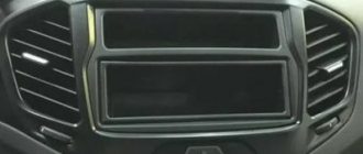
First we need to purchase a transition frame. One of the options is provided to us by the Asian brothers: link. There are many options both on Avito and on Yandex.Market.
In addition to the adapter frame, we need some cables to connect the rear view camera, the standard antenna connector, as well as the buttons on the steering wheel.
ISO connector - links: one two; Mini ISO connector - links: once twice; Adapter for antenna - links: one two; Connector for the rear view camera for Luxe equipment and higher - links: one two. I express my gratitude to the user Drive2: unnown
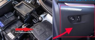
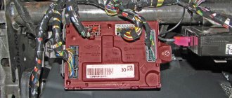
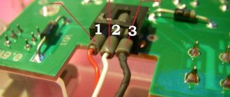
, helped a lot with finding the connector code. Before ordering, be sure to check through the emergency hatch of the trunk lock whether you have this connector; sometimes it happens that it is cut off at 0 at the factory. Otherwise, you will have to lay the wires yourself. What a “live” connector looks like, photo below.
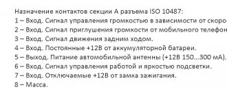
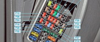
For successful work, we need to look at the electrical circuit of the car. For myself, I outlined a diagram of the connectors that are present in the car and will be needed when connecting. The diagram itself is presented below. We will rely on it further.
First of all, we remove the extra pins from the mini ISO connector, the result should be:
Before connecting, you should pay attention that if you are using a standard rear view camera, be sure to use a step-down power module on connector C7, because The standard camera operates at 6V. Still Chinese, usually 12V. From the mini ISO connector I brought out the usual AV yellow cable that came with the rear view camera itself. We take the power supply for the camera to the C7 connector from the ISO A1 CAM PWR connector. Be sure to remember to supply 12V to the connector of the active antenna amplifier C6, you can take it from the ISO A7 ACC cable, so the antenna will be energized only when the radio is turned on.
For the buttons on the steering wheel to work correctly, it is necessary to turn on the resistance according to the diagram. Connect connectors C13 - C15 to the ground of connector C19. We don't need anything more from the mini ISO connector.
Next we will work with the ISO connector, similarly freeing it from unnecessary pins
Here it is worth paying attention and bringing two cables from the mini ISO connectors C16 & C18, which will be responsible for the operation of the buttons on the steering wheel. As usual, I soldered and didn’t take any photos, but there are a couple of examples:
To connect a rear view camera, you need to connect the previously purchased connector according to the diagram, in the end you will get a universal adapter for any Chinese camera.
As a result, we connect the ready-made harnesses, each of the connectors, to the places provided for it. All functions of the radio work, the buttons on the steering wheel work. And, one of the advantages, I didn’t have to run the wire to the rear view camera.
If you have any questions, I will be happy to answer them.
I will leave additional links to the necessary accessories: Soldering iron: link Solder: link Heat-shrink casings: link Set of resistors: link Anti-noise tape: link
Basic functions and capabilities of the head unit
- Playing music files, radio;
- the ability to connect third-party accessories to play songs via AUX, SD card, other file drives, USB;
- displaying the current time and date on the display, both in active and inactive states;
- Hands Free option allows you to talk on the phone without being distracted from the controls;
- ability to connect third-party gadgets, functional equipment: rear view camera, tablet, navigation system.
Multimedia Lada Vesta, car multimedia radio control
Skoda Fabia white Logbook FAQ Installing a 2din radio
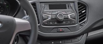
Appearance of the multimedia system and control units
The multimedia system, like the standard push-button radio, has the ability to connect a USB flash card, the connector for which is located below the climate panel. In addition to standard connection sources, the Multimedia version also contains a WI-FI module, with which you can connect to any network available to you.
Navigation in the Lada Vesta multimedia system
After these simple finger movements across the screen of your multimedia system, you will find yourself in the navigator menu. Navigator controls are designed to be intuitive, but some navigator controls may still raise questions.
Navigator controls:1. The “Collapse” button helps the user go to the main menu of the multimedia system (the navigator remains active)2. Using this button you can get to the quick access menu of the navigator3. An indicator showing whether the Mute4 button is enabled or disabled. Indication of Bluetooth connection5. GPS signal presence indicator (has three color variations; green - stable signal, yellow - searching for a signal, red - no signal)6. A mark showing your location7. A button that returns the map camera to your car if it is moved8. Time and date9. Compass - clicking on this button will rotate your map so that north is on top10,12. Button for correcting the tilt angle of the map image11. Map scaling13. Calling the main menu of the navigation program
Rear view camera on Lada Vesta
When the camera is activated, you can also see multi-colored stripes on the screen of the multimedia system, which are designed to tell the driver the distance to certain objects. Thus, the distance to the red stripe will be 30-40 centimeters, to the yellow stripe 150 centimeters and to the green stripe ~450 centimeters. download dle 11.1 watch movies for free
OEM radio controls
In the left corner there is a function key for activating/deactivating the radio. To the right there is a built-in microphone for conversations via Hands Free, and there is also a reset button to factory settings.
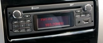
To the right is a monochrome display that displays basic information about tracks and radio frequencies.
Below is a slot for a storage card. It is mainly used for inserting a card and flashing the module, but if necessary, it can be used to read music tracks.
Below the perimeter there are preset buttons:
- MUTE – mute sound;
- Key to accept and reject calls (red and green);
- SCAN - multifunctional key for surfing the navigation menu;
- RADIO and AUDIO for switching playback modes from storage media;
- In the center of the structure there is a washer - a regulator for selecting functions, listing, changing the volume;
- At the very bottom there is a block with mechanical keys (6 in total) for quickly jumping to saved radio stations.
Lada Vesta head unit: price, articles
It often happens that the standard radio tape recorder breaks down and is unstable. When choosing and buying a new one, the owner has difficulty, since he does not know the catalog article.
| Name / catalog article | Price in rubles |
| Original MMS from LADA8450007949 | 33000 |
| Original MMS from ITELMA8450007949 | 14000 |
| Chinese models (AD-UNI707) | From 13000 |
| *prices are as of 04/04/2019 | |
Both modifications of the radio presented are absolutely identical, the difference in price is due to the manufacturer and trade markup.
Replacing the original radio
Many car enthusiasts “for various reasons. Purchasing and installing a new one is not difficult, the main thing is to choose the brand and manufacturer of the gadget.
There are many brands on sale, including Chinese ones. Choice from the cheapest to the most expensive, depending on the budget of the car owner:
- Multimedia center DVM 2117 iQ with Navitel software, price 32 – 34 thousand rubles;
- Chinese version of MMC for Lada Vesta (AD-UNI707) priced from 13,000 rubles.
There is already an article on the website about how to install an MMC radio on a Lada Vesta; in short, it looks like this:
- Remove the plastic frame.
- Remove four screws.
- Remove the standard MMC.
- Connect the blocks with wires.
- Fix the new radio (type 2-DIMM).
Lada Vesta wiring diagram
A general wiring diagram is too cumbersome and difficult to understand, so diagrams are used to show the individual connections.
Please note that each diagram contains performance tables that indicate the designation of the harness in question depending on the vehicle’s configuration.
The Lada Vesta wiring diagram shown is black and white, and the colors of the wires are indicated by letters. The decoding is in this table:
Wire colors
Front wiring harness
Shows the location of the following elements:
- headlights;
- sound signals;
- cooling system fan;
- sensors (wheel speed, air temperature, hood position, etc.);
- engine control units and ABS;
- canister purge valve;
- alarm switch;
- windshield wiper drive;
- windshield heating element;
Rear wiring harness
Displays the location of devices such as:
- additional body electronics units;
- sensors (rain, cabin air, wheel speed);
- interior lighting control unit;
- fuel tank.
Connecting the battery to the housing
A simple diagram for connecting the negative terminal to ground of a Lada Vesta car.
Engine ground wire
Everything is also simple and clear.
Front doors
The connection of the following elements of the Lada Vesta is described:
- locks;
- lampshades;
- window regulators and their switches;
- speakers;
- mirror drives.
There are also switch blocks in the left door of Vesta.
Backdoor
Everything is simpler here: the lock, the speakers and the power window switch.
Ignition system
This harness connects all devices related to the operation of the ignition on the Lada Vesta:
- sensors;
- motor control controller;
- battery;
- generator;
- circuit breakers;
- timing control valve;
- reverse light switch.
GPS navigation connection diagram
There is no need to additionally purchase a GPS antenna for the Lada Vesta, since it is already included in the standard package by default (cat. article 8450008475).
This decision on the globalization of satellite communications was made by the Government of the Russian Federation in 2014.
On the Lada Vesta “Lux” modification, data is supplied to the MMC via the CAN bus. After installing the radio, you need to connect the cable to the mini-ISO connector according to the diagram (to C17 - CANL, to C20 - CANH). Now the standard CityGID program finds satellites.
Reviews
| № | Positive |
| 1. | Sergey Ivanovich , 44 years old (otzovik.com): I use the standard radio, the quality is good, the functionality is sufficient. |
| 2. | Fedor Stepanovich , 40 years old (www.zr.ru): my comrades are all agitating me to install a 2-DIMM stereo system. I haven’t decided yet, because the price is steep, but the offer is good. |
| 3. | Vitaly , 22 years old (autobann.su): the quality of the standard MMC is not great, but it will last for several years, and then I’ll buy an imported one. |
| 4. | Daniil , 33 years old (lada-vesta.net): The factory stereo system is not bad, functional, no complaints. |
| 5. | Vitaly Semenovich , 43 years old (otzovik.com): for me, sound quality is not important, so MMS suits me, no comments. |
| 6. | Stepanovich , 44 years old (www.zr.ru): Three years have passed since the purchase of the car, all components are working properly, the condition is as if from the factory. |
| 7. | Vasilyevich , 20 years old (autobann.su): my positive review of domestic transport and assembly. A worthy car, a rival to many European brands. |
| 8. | Tolik , 43 years old (lada-vesta.net): I’m not a music lover, for me the quality and purity of sound are not particularly important. The phone is always on in the car. |
| 9. | Stepan Nikolaevich , 39 years old (otzovik.com): it has been working properly for two years, no special comments. |
| 10. | Konstantin , 43 years old (www.zr.ru): I’m happy with the purchase of the car, the interior is quiet, the acoustics are good. |
| 11. | Anton , 35 years old (autobann.su): after three years of operation, I can’t say anything bad about the MMC. |
| Negative | |
| 12. | Dmitry Viktorovich , 44 years old (www.zr.ru): constant problems with the firmware, glitches periodically. |
| 13. | Sasha , 37 years old (otzovik.com): in six months I’ve already been to a service station twice, with an electrician, changing relays and switches. |
| 14. | Nikolai Vasilyevich , 46 years old (autobann.su): replace the standard radio with an imported one, the sooner the better. |
Messages 4
1 Topic from SinySenya 2014-09-24 14:43:25 (2014-09-24 14:47:24 edited by SinySenya)
- BlueSenya
- New member
- Inactive
- Messages: 6
- Thank you: 0
Topic: Installing a subwoofer or what kind of bass do we do in Vesta?
Hello guys, the car hasn't come out yet, but I'm already thinking about installing a subwoofer in the trunk of the Lada Vesta. Maybe someone has already installed high-quality bass in the basins? I'm looking at them, can anyone give me some advice?
I want it to swing normally
2 Reply from Axel 2016-02-20 16:38:25 (2016-02-20 16:42:35 edited by Axel)
- Axel
- Participant
- Inactive
- Messages: 973
- Thank you: 139
Video - Installing Applauncher and Easy Connected
From the moment I bought the car, the plan was to install MMC on Android, I like it better than WinCE. For installation, I chose an inexpensive device, which in terms of functionality and quality suited me quite well - ACV 7610 (RUB 12,000).
Total about 15,700 rubles. I found the pinouts for the luxury Lada on the Internet, and the pinouts for the radio were in the manual.
Let's get to work. We will not cut the original wiring; we will use donor adapters for switching. First of all, we make a male-to-female ISO A and B adapter. To do this, we use the ISO A and B connectors with wires from the radio kit and the purchased ISO A and B male connectors. We connect part B, which is responsible for the speakers, one to one, there are no problems here. The most important part is A, where the power and controls sit. You have to be careful here.
On the Lada connector, power is supplied from the battery to A4, power from the ACC ignition switch is supplied to A7, and on MMC ACV it is exactly the opposite: A7 and A4. They need to be connected correctly! For what? - Further. In order to prevent the radio from turning off when starting the engine, we attach a simple circuit to the ACC wire.
We select the capacity based on the desire for the duration of operation of the radio without an ignition key. With a capacity of 10,000 μF, I was able to operate for 3 minutes, with a capacity of 2,200 μF - 45-50 seconds, I didn’t experiment further, but the logical series can be continued. If you cross-connect (see above), it will not work.
About connecting the buttons on the steering wheel. In connector A of the radio there are three wires A1, A2, A3, labeled Key1, KeyGND, Key2, respectively. We use them to connect to C16, C19 and C18, respectively, in the blue Lada block. We cut and connect in the donor adapter! C16 and C18 are two white wires, they can be connected to A1 and A3 in any combination, C19 is black, ground, black with black) Next, solder 100 resistors to wires C13 (blue), C15 (white-blue), C14 (white-red), 220, 330 Ohms, respectively, we put them in heat shrink, solder the other ends together and solder them to the black wire C19, we insulate everything.
FakeHeader
Comments 52
Hello. Tell me how you became friends with Elm.
Yes.elm I only have the bluetooth version
In addition, there was a +12 output from the reversing light in the camera wire (a separate wire), it was connected to the corresponding wire of the radio. - - - with which? What was the name of the wire?
The picture of the radio pinout shows the BACK wire. +12 reverse is supplied to it, this locks all functions of the radio and only the image is displayed
Doesn't turn on when engine is off
In what position is the ignition key?
in off (Ignition off)
If you connected everything correctly, this is correct. This is not a paradox. If you want constant operation of the MMC, then you need to power it not using + 12V from the ignition switch (ACC), but by taking the constantly hanging voltage used to power the MMC settings memory. It's clear?
From which contact do you supply power to the antenna amplifier? Lada westa sw cross.
Signed on the picture. Take from C4
Standard cameras have appeared in Westashhop. Price 5K
My friend, if the radio has only one wire to control the steering wheel, then how?
China radio, wire 10 in the photo
Connecting the three-wire interface of the multifunction steering wheel to the (one) two-wire interface of the radio The standard resistive interface of the radio control buttons on the steering wheel of a car usually contains three wires: KEY1(SW1), KEY2(SW2) and KEY GND. At least for Toyota, this is the case if the radio control is not implemented via CAN BUS (we will not consider this case). In radios manufactured in China, there are usually also three separate wires allocated for this: KEY1, KEY2 and KEY GND. In this situation, we connect the corresponding wires to each other and configure the necessary buttons in the radio.
But it happens that the radio has only one wire dedicated to the multifunction steering wheel. In this case, you can try the following scheme: connect the KEY GND wire from the steering wheel to the body of the radio, the brown (usually) wire KEY1(SW1), which controls the volume and switching tracks, to the KEY wire of the radio, and the gray KEY2(SW2), which controls the radio modes MODE, through a 5.1 kOhm resistor we connect to the brown wire KEY1 (SW1). After that, we go to the radio settings and check the operation of the resulting circuit in the Steeering wheel control settings, setting up the buttons we need. In theory it should work