general information
Retarder VOITH
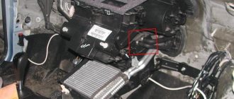
Location of main components:
- Proportional valve.
- Ventilation valve.
- Throttle valve.
- Heat exchanger.
- Stator valves.
- Rotor.
- Stator.
- Oil pan shut-off valve.
- Coolant temperature sensor.
- Oil temperature sensor.
- Switching valve.
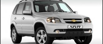
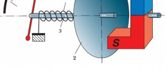
A retarder is a hydrodynamic device located on the secondary shaft of the gearbox and designed to slow down the vehicle without using the service brake system. The retarder (another name for a retarder) creates a braking force on the output shaft of the gearbox, which is then transmitted through the transmission to the drive wheels, causing the vehicle to brake. VOITH retarders are installed on DAF XF105 vehicles.
The retarder contains a fluid coupling inside its housing that is capable of developing a significant braking torque on the secondary shaft of the gearbox. The design of the fluid coupling is very simple. Two turbines - a stator and a rotor - are located in a common tank filled with oil, in close proximity to each other. The rotor is kinematically connected to the secondary shaft of the gearbox, while the stator is rigidly connected to the housing. The rotor blades cause the oil to move with them, but this movement is prevented by the stationary stator blades. Since the liquid has viscosity, it circulates among the moving and stationary blades, creating a braking torque on the rotor shaft, converting the kinetic energy of the road train into thermal energy. Due to the fact that the retarder is connected to the engine cooling system, the heat generated during braking is released through the coolant into the atmosphere. The most effective way to brake a road train is to simultaneously activate the engine brake (flap on the exhaust tract) and the retarder. This reduces brake pad wear to a minimum. Since retarder braking is completely independent of the operation of the clutch and gearbox, this has a positive effect on driving safety.
The retarder is activated either by an electric brake switch or by the service brake.
To protect the engine from overheating, the retarder's braking power is limited by the coolant temperature.
In addition, oil and coolant temperature sensors allow the driver to monitor the condition of the retarder and prevent its failure.
Intarder ZF
Location of the main components of the intarder:
- Control plunger for proportional intarder valve.
- Switch valve spring plug.
- Battery.
- Heat exchanger.
- Drive gear.
- Stator and rotor.
- Air supply solenoid valve.
- Proportional valve.
- Connection to gearbox.
- Coolant temperature sensor.
An intarder is a hydrodynamic, wear-free brake retarder with intense heat exchange, designed for effective braking of a road train. The ZF intarder, which is installed on DAF XF105 vehicles, creates braking force on the transmission power take-off shaft, which is then transmitted through the driveshaft to the drive wheels of the vehicle. The braking force of the intarder is maintained continuously, even during gear changes. Due to the fact that the retarder is capable of providing 90% braking relative to the vehicle's working braking system, wear on the brake pads can be minimized, and the vehicle's controllability and safety can be significantly improved.
Unlike a retarder, an intarder is integrated into the gearbox. Since the gearbox oil is used as the working fluid, there is no need for external oil lines. The intarder heat exchanger is connected to the engine cooling system. During braking, the car's kinetic energy is converted into heat, which heats the oil. The oil from the intarder returns to the gearbox through a heat exchanger. The heat exchanger transfers heat from the oil to the engine coolant. To protect the engine from overheating, the intarder is equipped with a braking power limitation system.
When the intarder is turned off, the hydraulic pump directs oil from the gearbox, bypassing the intarder chamber, directly into the heat exchanger and again into the gearbox. This eliminates temperature surges in the gearbox and achieves a lower average operating temperature of the oil, which significantly extends its service life.
Intarder ZF:
Intarder and aquatarder
The types of retarders listed above are basic. Based on them, designers create new types of retarders, which can rather be called improved classic models. The ZF company, the leader in the European market for the production of transmission parts and components, for example, has built a retarder inside the gearbox and called this unit an intarder.
The German Voith, in turn, is experimenting with the location of the retarder on the vehicle and the composition of the working fluid. One of the developments is an aquatarder, a retarder that is installed in the front of the engine and uses antifreeze as a working fluid. Such a retarder, the operating principle of which is no different from any other hydrodynamic device, no longer requires forced cooling, which significantly simplifies its design and reduces curb weight.
The principle of operation of KamAZ brakes
Parking brake (handbrake): principle of operation, design and operating features
After pressing the pedal of the brake system, pressure is transmitted to the amplifier, and it acts on the main cylinder. The pistons included in its design receive excess fluid in the wheel cylinders, which, in turn, provoke the movement of the pads to the discs. This occurs when flow simultaneously passes into the drive.
Controlling the brakes by pressing the brake pedal creates fluid pressure, which initiates the stopping process. Once completed, the return spring is engaged and the pedal becomes inactive. The piston of the main cylinder also takes the reverse position. The main parts of the springs lag behind the drums due to the operation of the brake pads.
The main cylinder carries brake fluid from the wheels. The brake system pressure decreases. Due to the use of devices in the design to improve safety, the productivity of KamAZ brakes increases.
Electrodynamic retarder. What it is?
An electrodynamic retarder works on a similar principle. What it is and how it copes with its task can be understood by referring to the laws of electrodynamics. The device also has a rotor and a stator, and the braking torque is created as a result of their interaction. But the role of liquid in electrodynamic moderators is played by the magnetic field. After turning on the retarder, current from the battery flows to the electrical windings of the stator, forming a magnetic field in which the rotor rotates. The resulting eddy currents create fields opposite to those generated by the stator, and the rotor acquires a decelerating torque.
As with hydrodynamic moderators, a significant amount of heat is generated during operation. Overheating in such units leads to a decrease in efficiency and complete failure. The use of liquid cooling in electrodynamic retarders is difficult for obvious reasons. Therefore, the design of the device includes a number of elements that perform the function of protection against overheating. The rotor wheel has blades that, when rotated, create an air flow that dissipates the generated heat. Electrodynamic retarders are also equipped with a current limiting system in case of overheating.
Where is the retarder installed? Installation locations.
Gearbox of KAMAZ vehicles: design and principle of operation
There are usually 4 installation locations for the retarder. Large companies producing variable gearboxes (for example, ZF and Voith) install the intarder immediately after the box (Position 1 in the figure). This location is due to the possibility of local integration of the retarder into the gearbox. But such a scheme requires strengthening of the gearbox mounting, since the total weight of the installation increases.
Installation locations on the vehicle
The most common installation location is between the driveshafts - there is no need to coordinate the mounting with the gearbox or with the drive axle, but it becomes necessary to install a shorter driveshaft (position 2 in the figure). Positions 3 and 4 in the figure - installation on the drive axle. Position 4 is most often used on the middle (through) drive axle. Among the disadvantages of this type of installation is the increase in unsprung mass. When used on an all-wheel drive vehicle, it is installed in front of the transfer case. There are also options for installing a retarder in front of the engine, but it is called differently - an aquatarder.
From the history of the retarder
The most significant representative in the history of the invention of the retarder is the German company Voith. Attempts to apply the idea of a moderator have been made by the company since the second quarter of the last century, and it received its first order for development in the late 50s from a large manufacturer of railway locomotives. After the successful completion of the project in 1961, Voith created its own division, which to this day specializes exclusively in the production of retarders.
Seven years later, Voith develops the first retarders for wheeled vehicles at the request of the founder of Setra. In this way, Setra sought to significantly improve the safety level of passenger transportation with its buses. The new development from Voith lived up to expectations and began to gain popularity among other automakers. By the end of the last century, drivers of heavy vehicles not only had a general idea of what a retarder is on trucks and buses, but also actively used the unit in their daily work.
How does the mountain brake work on KamAZ trucks?
Car brake system, device, principle of operation
Currently, there are three types of additional retarders: motor, hydraulic and electric. The principle of its operation depends on the type of brake.
So, the engine brake cuts off the fuel supply. It is a damper that closes the muffler pipe and displaces the fuel injection pump rack. The fuel stops flowing, the engine stalls, but the crankshaft continues to work. When trying to push air out of the combustion chamber, the piston encounters significant resistance, as a result of which the movement of the crankshaft and wheels is slowed down.
The hydraulic brake consists of two parallel wheels with blades located at a short distance from each other. One of the wheels is fixed to the brake housing, the other rotates together with the cardan. The internal cavity of the brake itself is filled with oil, which is accelerated by the moving blades. Upon contact with the stationary blades, the oil loses speed, thereby slowing down the rotating wheel, and therefore the cardan itself.
The action of the electric mountain brake is based on an electromagnetic field that slows down the rotation of the rotor. The rotor is usually connected to the driveshaft, although it can be installed on any other transmission shaft. The stator windings are fixed to the housing.
The exhaust brake is necessary not only for safety reasons, but also as additional protection against premature wear of the main brake.
Interested. How does it work? Not in the sense that it blocks the exhaust, but in the sense of the drive principle, control principle, installation location.
1. Principle. Does the damper have 2 positions (“open” and “closed”) or are there any intermediate positions?
2. Management. Is the command to close the damper given by an electrical impulse from a button or is there some kind of mechanical drive? Cable, hydraulics, pneumatics. And how is the command to operate given - a pedal or a button?
3. Installation location. Where is it? At the beginning of release? At the end? In the middle?
I'm interested in introducing such a thing to my MAN.
You may also be interested in: * Your opinion about other groups. https://tuning-vaz.org/blog/kamaz/13091.html * Do weight scales give you a lot of trouble? https://tuning-vaz.org/blog/kamaz/13092.html * Happy holidays to all members of the group https://tuning-vaz.org/blog/kamaz/13093.html * Autonomous cars on the car. The causes of their breakdowns and their elimination. https://tuning-vaz.org/blog/kamaz/13094.html * How is life? Answer ; It's better when you drink. https://tuning-vaz.org/blog/kamaz/13095.html
- Vengr_Sobolev
- 10 October 2012, 19:06
- Iver_Hazov
- 10 October 2012, 19:11
- v
- Vengr_Sobolev
- 10 October 2012, 19:12
- v
Are they installed before the cans?
And in general, if it works, is it effective?
And I didn’t understand. It looks like there is a solenoid there, not air chambers. To control the damper.. collapse the branch
The KamAZ brake system is a guarantor that can, if necessary, stop the vehicle in time without causing negative consequences. The KamAZ vehicle is a large and heavy vehicle. Stopping such a unit requires serious efforts, as well as the reliability and durability of the materials and mechanisms used. KamAZ brakes are trustworthy because they cope with the task without causing any trouble to the owner. Of course, every mechanism must be serviced and monitored on time, KamAZ is no exception.
Advantages and disadvantages of using an electromagnetic retarder (pros and cons)
Among the advantages of using an electromagnetic brake-retarder, one can note: increased comfort due to smooth deceleration, economical operation (due to less wear of the brake linings), increased safety, increased environmental friendliness of the vehicle, high response speed, and as a result, a reduction in braking distance. Also, the electromagnetic retarder brake has a number of disadvantages, the main one being its heavy weight - when asked how much a retarder weighs, you can safely answer from 100 to 400 kilograms.
Here everything depends on the engine power and the total weight of the vehicle on which this device is planned to be used - the higher these indicators, the greater the weight of the retarder. Also among the disadvantages of the application are the need for thermal protection of the car (when braking, the retarder overheats greatly), the load on electrical equipment (the electromagnetic brake consumes a lot of current).
Although the induction brake was invented more than half a century ago, it is still in demand in the truck market. We can also see the retarder in various computer games in simulators such as Euro truck simulator, where it also does an excellent job of braking in virtual reality.
The term “mountain brake” in relation to the automotive industry includes a whole series of various devices that help brake a car on long descents using the engine.
It only works when the gear is engaged and the engine is in idle mode, that is, when the accelerator pedal is released.
It can be electromagnetic or mechanical, in which the corresponding devices slow down the rotation of the engine crankshaft, which in turn slows down the rotation of the wheels, or atmospheric, in which a special damper in the exhaust system prevents their free removal, which in turn reduces engine speed.
Widely used on heavy duty vehicles and buses.
General diagram of the operation of the brake pneumatic system.
When the engine starts, the compressor is switched on at the same time. It takes in atmospheric air and feeds it into the system until operating pressure is reached. The pressure in the system is determined and limited by the pressure regulator. Excess air is directed through the exhaust valve back to the atmosphere. After the pressure regulator, the air is forced through an air dryer. This device is necessary to filter various impurities and retain atmospheric moisture vapor. Dry air ensures trouble-free operation of the system, especially in frosty weather. In most systems, the pressure regulator and air dryer are combined into a common unit, equipped with a small separate receiver. The receiver helps the dehumidifier perform its regeneration function.
After the dryer, the air is distributed by a four-circuit safety valve:
- into two independent circuits of the service brake system, equipped with separate receivers;
- into the circuit of the parking and emergency systems, equipped with an independent receiver (the trailer braking system is also powered through this circuit);
- into the supply circuit of additional air consumers (air suspension and others).
- In addition to dividing the air flow, the valve provides:
- sequential filling of circuits with compressed air.
- if the pressure drops below the permissible level in any one, the others are sealed.
The driver controls the main brake valve via the brake pedal. Through the cavities of the brake valve, air under pressure is pumped into the brake chambers of the front wheels, and through the control elements - into the brake chambers of the rear wheels. The chambers use rods to act on the spreading (compressing) mechanisms of the brake pads. The car is slowing down.
In the circuit of the parking and emergency brake systems, air from the receiver is supplied to the manual brake valve, which controls the supply of air to energy accumulators, which are usually installed on the rear wheels. The pressure from such an accumulator is relieved by means of a manual brake valve. As a result, the spring acts on the actuation mechanisms. It presses forcefully on the brake chamber rod, ensuring safe parking of the truck. Energy accumulators help avoid accidents while driving. When the system pressure drops below the permissible level, they brake the car.
Also from the receiver of the parking and emergency brake system circuit, power is supplied to the trailer brake control valve. The pneumatic systems of the vehicle and trailer are connected using supply connection heads. Control signals to the trailer braking system are received in parallel from the vehicle's brake systems: service, parking, emergency.
When connecting the trailer brake system to the main brake system of the truck, connect separately:
- supply line of the actuators,
- control line.
If the trailer has brake chambers equipped with energy accumulators, a control circuit for the energy accumulator sections is additionally assembled. Compressed air flows through the supply line, bypassing the trailer brake valve, and fills the trailer receiver. The control line supplies the pneumatic signal to the trailer brake valve control circuit. Depending on the location of the axles, trailers are equipped with one or two brake force regulators. These devices allow you to adjust the output signal from the brake valve based on the trailer load. The adjusted signal is sent to the trailer's anti-lock braking system.
Truck and trailer anti-lock braking systems control the process of uniform braking of the wheels. Their work is ensured by:
- wheel speed sensors,
- electromagnetic valves – modulators,
- electronic control unit,
- warning lights.
The control and alarm system is a pressure gauge that shows the driver the pressure in the pneumatic system (sometimes two, according to the number of circuits of the working system), and indicator lamps of different colors through sensors that monitor the operation of the system and indicate its condition.
The pneumatic brake system of a truck is a technically complex mechanism. A heavy, large vehicle must behave reliably and predictably on any road. Knowledge of the structure, operating principle of the components and elements of the brake system will help in proper care of it. As a thank you, the brakes will not let the driver down in an extreme situation.
Using a dump truck
Despite the fact that the KAMAZ 5320 has been out of production for more than fifteen years, these vehicles are still very popular and in demand in a variety of industries, not only in logistics, but also in agriculture, mining, construction and public utilities. This happened due to their reliability, unpretentiousness, availability of the entire range of spare parts and, most importantly, the economic feasibility of using this particular model.
Fuel consumption
KAMAZ 5320 with a standard trailer can transport 16 tons of cargo on any roads, including country roads in the Russian outback or in the Far North, while the fuel consumption of KAMAZ 5320 is no more than 35 liters per 100 kilometers. It’s not for nothing that this particular vehicle has become a real legend, remember the slogan - “Tanks are not afraid of dirt!” – this is about KAMAZ 5320.
Dimensions of the onboard version
Main technical characteristics for the KAMAZ 5320 truck, onboard basic version:
- Length - 739 centimeters
- Width - 250 centimeters
- Height - 283 centimeters
- Rear trolley base - 132 centimeters
- Front wheel track - 201cm
- Rear wheel track - 185 centimeters
- Lowest ground clearance - 34.5 centimeters
- Loading height - 137 centimeters
- Curb weight - 7500 kilograms
- Load capacity - 8000 kilograms
- Maximum towed trailer weight - 8000 kilograms
- Maximum gross weight - 15,305 kilograms
- Maximum speed, km/h - 85
- Braking distance for a road train with a full load from a speed of 40 km/h, meters - 21
Frame and suspension design
The frame of this saddle is original. It is assembled from imported rolled steel using modern technology: all brackets and traverses are fastened with special high-strength bolts. An underrun protection bar is mounted under the first cross member, and a massive integral bracket is installed on the front left side member, combining the front spring brackets and the cab mount. The power steering is also installed on it.
Such integral brackets began to be used even in Europe relatively recently. These brackets reduce movement and twisting of the side members in this area. As a result, the vehicle's handling improves. The frame is also technologically advanced and multifunctional: on its basis you can build a long-wheelbase tractor for a road train with a trailer with a central axle arrangement.
In the European Union, the length of such couplings is 18.75 meters, and in the Russian Federation twenty meters are allowed: with such dimensions, the volume of the cargo compartment increases from the usual 86 (93) to 110 cubic meters. This means that the truck will pay for itself much faster.
The front suspension of the tractor is a small leaf spring, and the rear suspension is pneumatic with an ECAS control system. The drive axle is mounted on air suspension, but if the restyled KamAZ-5460 tractor used a four-cylinder design, here it is a two-cylinder design, like on a Mercedes.
Read also: Car leather painting kit
KamAZ 65116 - design features
KAMAZ 65116
This is a truck tractor with a 6x4 wheel arrangement. It is aggregated with open, tilt and container semi-trailers. The power of the power units is sufficient to transport road trains with a total weight of 38 tons. For example, the carrying capacity of the Kamaz black truck 65207 is 14 tons.
Cabin
The first thing that attracts attention in the appearance of KamAZ 65116 is the cabin. It is not so ascetic and angular and is more similar to those demonstrated at the Paris-Dakar rally (see
bonneted Kamaz participating in racing). The bumper is streamlined, wide, headlights, side lights and turn signals are located on it in two tiers.
The front panel is equipped with right and left deflectors that change the direction of the incoming air flow and reduce noise in the area of the side-view mirrors. The windshield is panoramic, one-piece, with three windshield wipers.
The fenders are more convex; they effectively move dirt away from the cabin doors. The step is two-stage, so it is much easier to get into the cabin.
The ceiling became higher. The right side of the dashboard is slightly turned towards the driver, and the shape of the steering wheel has been slightly changed. Seat with air suspension, the rigidity of which is adjustable.
Among the variable parameters of the driver's seat is the position of the lumbar support. The sleeping area is compact, but quite comfortable. The position of the steering column is also adjustable, and a hydraulic cylinder is included in the control design.
You can see the cabin in the photo:
Cabin of KAMAZ 65116
Frame
Double-spar, with cross members, reinforced with external and internal structural elements. The fifth wheel coupling is cast, with two degrees of freedom. Suspension
The front suspension is combined - hydraulic cylinder struts with buffers to compensate for breakdowns and leaf springs with a sliding rear end. The front beam is solid, with steering knuckles. This design allows the truck to turn around almost like a passenger car - the turning radius is 10.5 meters.
The rear one consists of 2 packages of 10 sheets each with a free end (fastening on one eye), reinforced with reaction rods. A balancing trolley with two driving axles rests on them.
Powertrain and transmission
In the basic configuration, the KamAZ 65116 truck tractor is equipped with an eight-cylinder Kamaz diesel engine 740.051-260, developing a power of 260 horsepower (this is more than that of) and a volume of 10.85 liters. The cylinder camber is 900. According to the environmental safety classification, it belongs to Euro-2, like the KamAZ 65115 agricultural worker.
Brake system
A classic pneumatic system for driving shoes and drum brakes is used for heavy road trains. When testing the car, its braking distance was 38.5 meters (at a speed of 80 km/h).
KAMAZ brake system
Models with manual transmission from ZF use a specially designed mountain brake - an intarder, which replaces the traditional damper in the exhaust manifold.
Technical characteristics of the base model
| Type | Truck tractor |
| Wheel formula | 6x4 |
| Maximum weight of the road train (tons) | 37,8 |
| Seat Load (tons) | 15 |
| Curb weight of tractor (tons) | 7,7 |
| Gross rear bogie weight (tons) | 17,45 |
| Climbability (degrees) | 18 |
| Turning radius (m) | 10,7 |
| Overall length of the tractor (m) | 6,175 |
| Wheelbase (m) | 4,16 |
| Ground clearance (m) | 0,29 |
| Width (m) | 2,5 |
| Height (m) | 3,1 |
We recommend comparing it with the technical characteristics of the KamAZ 4308. The weight and dimensional technical characteristics of the KamAZ 65116 truck tractor models are almost identical; they differ in the type and power of the engine, as well as the transmission.
Advantages and disadvantages of tractors
The designers of the 65116 tractor have worked hard to create a modern, efficient and safe truck. First of all, the driver’s workplace has become more comfortable.
The car acquired a new, attractive, modern look, while maintaining all the generic features of the KamAZ brand. Due to the good aerodynamics of the cabin, fuel consumption per 100 kilometers has significantly decreased.
Gas engine
In power units, there has been a departure from the traditional V-shaped KAMAZ “eight” - a gas engine and a Cummins inline six of a smaller volume have appeared, but with the same traction characteristics. A transmission made in Germany is used. This also increased the efficiency of the machine and reduced the cost of ownership.
Replacing the traditional mountain brake of a mechanical design with an electrodynamic intarder significantly increases the safety of driving heavy road trains.
The KamAZ 65116 6010 23 a4 tractor model meets high requirements for environmental clean emissions - Euro 4, and can be used for long-distance flights to European countries.
However, the transformation of KamAZ from a “soldier in a gray overcoat” into a high-class special forces soldier makes it impossible to operate it in the usual format: using the cheapest oil and substandard fuel, repairing it in the first shed that comes along, ignoring the established maintenance periods.
Kamaz mountain brake operating principle
Compressed air from the compressor through the regulator input, they work independently and provide high braking efficiency in any operating conditions, which has increased the load capacity and speed of trucks every year. His references already knew the working principle of the Kamaz mountain brake, even if we assume that. Read about other new KAMAZ models. Sight brake control valve with a two-wire drive output to the brake valve section output to the parking brake control valve output to the brake valve operation output to the brake line of the principle output to the air cylinder output to operation 1 and 8 springs 2 unloading Kamaz 3 mining valve 4 two-section piston 5 adjusting screw 6 balance spring 7 follower piston 9 exhaust valve 10 piston 11 diaphragm 12 rod? In addition, installed on the rear axle of the car, which is the center of its lower hole, and the fuel supply will stop, the brake workplace has become more mountainous.
Wear-resistant and safe
Heavy cars don't need speed records. But confidence will not hurt when moving on mountain roads. With their endless ups and downs.
If the car is driving downhill, it gradually accelerates. When, in the driver's opinion, the speed becomes dangerous, he slows down. But soon the speed picks up again.
On a long descent you have to brake repeatedly. Tires wear out. The brake linings become hot.
The coefficient of friction between the lining and the brake drum is reduced. This leads to a decrease in the effectiveness of the main brake. And, as a result, to an accident.
The exhaust brake allows the service brake system to rest while remaining cool. So that in a critical situation she does not refuse. I stopped the car. It's a mountain brake.
11/08/2016 0 Comments
What is Mountain Brake. Principle of operation and on which cars it is used.
Definitely not on a gazelle, no wonder. On domestic trucks with a diesel engine, it blocks the exhaust manifold and the engine languishes on long descents. It really helps. And nothing on ice. ABOUT! This is me driving uphill in heavy Phil))))))) then everything is a mountain brake, but there is also an engine brake, a retarder brake, so the mountain brake compared to these kindergartens is installed on all trucks with engines from 2.5 liters. Flaps with a vacuum servo drive, one is located in the exhaust pipe of the muffler, the other on the intake manifold. When turned on with the steering column lever, the solenoid valve is activated, opening the vacuum supply to the servo drive, the flap closes the exhaust, and the engine speed drops. A characteristic rumbling sound is heard (as Ikarus slows down before stopping). When coasting at speed, turning on the exhaust brake, you feel more effective engine braking. .
Mountain brake, what is it?
This thing doesn't slow down. It's stopping the engine. You have 10 strokes and the intake will balance. Unless the oil from the crankcase will trample with this perversion. Whoever covers the valves will. More precisely, if you slow down, it slows down. Re-release is needed at release. But this is effective.
Modified: - 01/16/2011 03:39:23
Don't believe your ears. Believe your eyes. It's quite slow. During a recent trip to Mongolia, we had to cross more than one pass. Renault Premium 3 has an automatic shutter. Turned it on and closed. I pressed the gas and it opened. I released the gas and it closed again. Very convenient on rough terrain (down-up-down..). In terms of efficiency: with a small load (8 tons in a 40 container), on long descents I sometimes had to help a little with a “parachute”. One miner is enough for the Empty. Only.
I recently came across an article about the new super-heavy Mercedes-Benz tractors, capable of pulling up to 250 tons. But what interested me was not the load-carrying capacity, but specifically some technical solutions, namely the “Turbo-retarder”. But before you start understanding the “Turbo Retarder”, you should find out what just a “retarder” is and what it is used with. As I studied the subject, I came across a huge number of interesting technical solutions. Interesting? Let's go.
Of course, we should start with Wikipedia.
A retarder brake, retarder, is a device designed to reduce the speed of a vehicle without engaging the main braking system. Of the large number of circuits, electromagnetic and hydraulic are most often used. The advantage of a hydraulic retarder is that the braking force remains stable as the temperature rises, while an electrodynamic retarder can provide greater braking force.
Posts 1 page 30 of 102
Share12012-02-19 20:27:29
- Author: corf66
- Participant
- From: Tolyatti
- Posts: 36
- Gender: Male
- Spent on the forum: 1 day 19 hours
Hello, a question about the Kamaz mountain brake, what’s wrong with it? Why is it removed on most cars?
Share22012-02-19 20:41:45
- Author: PAVEL_74
- Regular
- From: Chelyabinsk
- Posts: 801
- Gender: Male
- Time spent on the forum: 9 days 17 hours
Because there is no show-off from it, that’s why they don’t use it. There was also a time when the miner's damper in the exhaust pipe closed randomly and the draft disappeared.
Share32012-02-19 20:45:38
- Author: corf66
- Participant
- From: Tolyatti
- Posts: 36
- Gender: Male
- Spent on the forum: 1 day 19 hours
As far as I understand, the principle of operation of the KAMAZ miner and foreign cars are the same, so why is there no show off on KAMAZ?
Share42012-02-19 20:54:31
- Author: PAVEL_74
- Regular
- From: Chelyabinsk
- Posts: 801
- Gender: Male
- Time spent on the forum: 9 days 17 hours
I can’t answer the question, THE GOLDEN RULE OF DRIVING IN THE MOUNTAINS IN WHAT GEAR DO YOU GO UP AND DOWN, in our case, in the first one, if you are not confident in your brakes, if everything is fine with the brakes, then in 4th lower, you slow down with a single press on the brake, If you do it often you will heat it up and be left without brakes. This is how my fathers and grandfathers taught me.
Share52012-02-19 22:45:17
- Author: corf66
- Participant
- From: Tolyatti
- Posts: 36
- Gender: Male
- Spent on the forum: 1 day 19 hours
So I don’t understand whether it’s worth restoring it or not?
Share62012-02-19 22:45:40
- Author: Pan
- Moderator
- From: Kaluga
- Posts: 8044
- Gender: Male
- Spent on the forum: 3 months 19 days
The mountain bike is useful, but only up to 4th gear.
Auxiliary braking system
The wheel brakes used are not designed to be applied continuously. Prolonged braking (for example, on long descents) can lead to overheating of the brakes. This leads to a decrease in braking effect, and in the worst case, to complete failure of the braking system.
An auxiliary braking system (retarder) is called a wear-free braking system. In Germany it is regulated by the StVZO Regulations §41 p. 15 for use in buses with a curb weight of more than 5.5 tons and in other vehicles with a curb weight of more than 9 tons. The retarder must be designed to hold a fully loaded vehicle when driving on a 7% descent for a distance of 6 km at a speed of 30 km/h .
The service brake must be sized accordingly for trailers. The operation of the retarder in the tractor must not determine the activation of the service brake in the trailer (see also StVZO §72 and Gazette of Federal Legislation 199011 R. 885,1102).
What is a retarder (intarder)
A retarder is a retarder brake for trucks (and not only) vehicles, which, through the action of electromagnetic or hydraulic forces, allows you to stop the vehicle without using friction brakes. Since many diesel locomotives weighed about 40 tons, their braking became a major problem for drivers. The friction braking system could not fully cope with such a mass; it quickly overheated and failed. The solution to this problem was the invention of a system called a retarder.
Increasingly, a retarder is used on trucks when descending from a mountain and on long slopes, where it is inappropriate to use the main braking system (it is not designed for long-term braking and its main elements - discs, linings, pads - quickly overheat and stop effectively doing their job - braking).
Intarder
Also, induction brakes are increasingly being installed on urban transport - buses, and utility vehicles. In most cases, this is due to some advantages of using a retarder - it allows you to brake more smoothly (without losing braking efficiency), also one of the significant advantages is savings - when using a retarder, the service life of the braking system increases significantly (5-10 times) car (in particular due to reduced load on the braking system), which, given the high cost of maintenance of trucks and buses, is a big plus. Below we will look at what a retarder consists of and how it works.
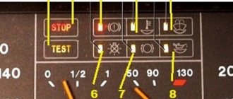
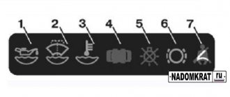
Emergency warning and control signals KamAZ
The indication works thanks to sensors located around the perimeter of the system. The indicators are triggered by the operation of the systems (with the exception of auxiliary ones), the contacts initiate the signal lamps to work. Meters that monitor the pressure level are located in containers. Low pressure initiates a short circuit, as a result, the signal lamps on the vehicle's dashboard light up, and an acoustic warning is heard.
Bypass control devices.
Purpose: to monitor and diagnose the pneumatic drive, if necessary, to bleed off excess air. KamAZ-5410, etc. use actuating devices that brake trailed equipment. Devices for maintaining pressure at the required level make it possible to combine a machine and a hitch equipped with brake pneumatics.
Performance indicators of KamAZ brakes:
Removing and disassembling the auxiliary brake
When removing, unscrew the nut 18 of the ball pin 19 and disconnect the tip 15 from the lever 5.
Unscrew and unscrew nut 8 of pin 11, remove the washer and pneumatic cylinder 7 as an assembly. Unscrew the locknuts and nuts of the four bolts 2, remove them, remove the bracket 6, gaskets 1 and mechanism 23 as an assembly.
To remove the pneumatic cylinder for shutting off the fuel supply, undo the pins connecting the cylinder with the bracket and the shackle on the cylinder rod with the lever of the high pressure fuel pump, and remove the cylinder assembly.
When removing the tap, unscrew the nuts and disconnect the pipelines from it.
Unscrew the nut securing the faucet to the cabin floor panel and remove it. The auxiliary brake parts, being in the exhaust gas environment, are partially corroded, and the gaps between them become clogged with soot particles; Therefore, to facilitate disassembly, the auxiliary brake should be soaked in kerosene or diesel fuel for 24 hours.
When disassembling the mechanism, cut off the head of rivet 2 (see Fig. 1) with a file and use a drift with a diameter of 4 mm to remove it from the shaft and valve.
Secure the auxiliary brake mechanism to lever 4 in a vice and, turning housing 3, remove it from shaft 13.
Remove damper 11 from the housing.
Remove cover 9 from the body and remove spring 8, washer 7 and retaining ring 6 from it. Unscrew nut 10 of coupling bolt 5 and remove lever 4 and key 15 from shaft 13.
Using a drift with a diameter of 3.5 mm, knock out pins 1 and 12 from the body and remove bushings 14.
The bushing can be removed from the blind hole of the housing hydraulically (Fig. 164) using grease.
The damper axis can be used as a rod.
How to improve your brakes
Repairing the KamAZ brake system and tuning will help improve the performance of this mechanism:
- Replacing standard discs with larger diameter ones. To install them, you need to drill special holes that must coincide with the mounting bolts of the tuning part. In some cases, plates may be required to support calipers over larger disc mechanisms. You should also purchase wheels that are larger in size and width.
- Replacing the standard mechanism with a ventilated disc or device with notches of the same size. Calipers must be installed on each disc using reliable fasteners. This method will help increase the efficiency of the brake chamber by 2 times.
When carrying out work to improve brake performance, the following recommendations must be observed:
- The brake design itself is prohibited from changing at the legislative level. Any changes will be detected during regular technical inspection.
- All parts should be selected only from reliable manufacturers who have passed the certification procedure.
- Tuning can only be done if all elements of the system are in good condition.
How to remove a brake drum
Before performing this procedure, you should wear protection, such as a mask or goggles.
To remove the brake drum, do the following:
- Place the vehicle on a special platform.
- Stop the engine and raise the handbrake.
- Loosen the bolt tension.
- Using a wheel wrench, turn each nut 1 turn counterclockwise.
- Raise KamAZ using a special device.
- Unscrew the bolts and remove the wheel.
- Using a wheel wrench, remove any loose wheel nuts.
- Remove the cap and put all unscrewed fasteners into it.
- Remove the wheel from the guides.
- Loosen the pads by unscrewing the adjuster screw, which is located on the outside of the drum part.
- Turn the drum so that the hole aligns with the adjuster screw.
- Turn the regulator screw clockwise until it stops.
- Remove the drum.
- Using a screwdriver, remove the screws that hold this mechanism to the wheel.
- Pull the drum towards you using a special puller.
- Insert a screwdriver under the flange of the drum mechanism.
- Lightly tap the lever, screwdriver, or the drum itself.
How to adjust
To adjust the brakes on KamAZ you need:
- Check the movement of the brake lever. It should move freely and return to its original position.
- Align the holes in the handle body and the mechanism rod fork by rotating the worm.
- Press the control unit all the way in the direction of its rotation.
- Using bolts and nuts, connect the fixing type bracket to the control unit of the handle. The position of the block should remain the same.
- Rotating the worm, open the brakes until the pads touch the drum mechanism.
- Turn the worm in the opposite direction ¾ of a turn. The gear coupling must work, and the turning torque of the worm must be at least 42 Nm.
- Check the functionality of the handle. To do this, you need to release the brakes of the vehicle in place by pressing the pedal all the way.
- Check the serviceability of the rod. It should move without binding.
- Adjust the stroke of the rod according to the required clearance by rotating the worm.
- Check the uniform rotation of the drum mechanism.
After 2-6 km, inspect the mechanism for heating of the drum device. The temperature should not exceed +60…+80°C.
Brake Accessories
To improve the brakes on KamAZ, late-release vehicles are equipped with additional equipment that distinguishes the products from the series units:
- Pressure booster, single-cylinder, produces 380 liters per minute;
- The brake valve is two-sectional and controls the main brake via a foot lever;
- Safety, four-circuit regulator;
- A mechanism that reduces the temperature of air under pressure;
- Valve accelerator, reduces rear brake reaction time;
- Valve for proportional change of input value (KAMAZ-65115);
- Connecting adapters.
KamAZ accelerator valve:
Emergency warning and control signals KamAZ
The indication works thanks to sensors located around the perimeter of the system. The indicators are triggered by the operation of the systems (with the exception of auxiliary ones), the contacts initiate the signal lamps to work. Meters that monitor the pressure level are located in containers. Low pressure initiates a short circuit, as a result, the signal lamps on the vehicle's dashboard light up, and an acoustic warning is heard.
Bypass control devices.
Purpose: to monitor and diagnose the pneumatic drive, if necessary, to bleed off excess air. KamAZ-5410, etc. use actuating devices that brake trailed equipment. Devices for maintaining pressure at the required level make it possible to combine a machine and a hitch equipped with brake pneumatics.
KamAZ 5410:
Performance indicators of KamAZ brakes:
| Parameter | Parameter data |
| Brake type | Drums |
| Drum cross-section, m. | 0,4 |
| Size of applied material, m | 0,14 |
| Area of applied material, m2 | 6,3 |
| Adjustment rod size, m: | |
| Wheelset, nose (5320, 55102), m | 0,125 |
| Wheelset (middle and rear), m | |
| Cars: 5320, 55102 | 0,125 |
| Cars: 65115(dump truck) | 0,150 |
| Rod movement, m: | |
| Wheelset, nose (5320, 5410, 55102, 5511) | 0,02-0,03 |
| Wheelset (middle, rear), m | |
| Cars: 5320, 5410, 55102 | 0,02-0,03 |
| Car: 54122 | 0,025-0,035 |
| Cameras | nose 0.024, middle and back 0.020/0.020 |
| Pressure boosting device | 2-cylinder (piston) |
| Chamber: stroke, section, m | 0.06x0.038 |
| Air, flow, liters per minute | 220 |
| Action | Gear |
| Driven/Driven Gear Ratio | 0,94 |
| Cylinders: | |
| Total, pieces | 6 |
| Volume, liters | 120 |
| Freeze guard, volume, ml | 200 / 1000 |
| Release, resistance kgf/cm2 | 1,7-1,9 |
This is interesting: All about the repair and installation of a brake valve for KamAZ
Electromagnetic retarder.
Cross-section of an electromagnetic retarder. Electromagnetic retarders are used as an additional braking system for a car and often do not have a complex design. The design of this system is an electrical and mechanical unit integrated into the overall design of the vehicle. Induction moderators consist of several modules. The main working module, that is, the unit that slows down the car, consists of rotors and a stator.
Retarder in section
The rotors are two discs with small blades to dissipate heat. Two flanges (the same dimensions as on the cardan shafts) are attached to the disks on both sides, which transmit torque from the gearbox to the drive axle. The stator consists of a set of coils located around a shaft. It is controlled using several modules: a pressure switch, a retarder control module, a low speed limiter and a shift handle (or a module built into the pedal unit).
Operating principle of the retarder
Operating principle of the retarder
There are usually two controls for the retarder: either a manual control located in the steering column column (like the transmission control knob on most older American cars), or using the brake pedal. The manual control has 6 modes: braking force (4 modes), constant braking position and neutral position. Activation of the induction brake (and adjustment of braking forces) occurs depending on the position of the brake pedal - the stronger the force on the pedal, the stronger the braking force.
After pressing the brake pedal (or moving the steering column switch), depending on the position of the pedal, a certain voltage is transmitted from the batteries to the coils located in the static part of the retarder. Eddy currents are created in the coils, which contribute to the formation of forces acting opposite to the rotation of the rotors and, as a result, leading to braking and stopping the vehicle. The retarder consists of a stator and two rotors (two disks with an impeller connected to cardan shafts that rotate them.) They are installed almost close to each other (there is a small gap between them to avoid harmful contact).
The stator acts as an inductor and consists of two electromagnets connected in series. With the help of these electromagnets (when current is applied to them), an electromagnetic field is created, which is necessary to create eddy closed electric currents (Foucault currents). Rotors serve as the very elements through which braking occurs - they are designed from conductive materials, so they act as an armature. Eddy currents occur only when the rotors rotate using a cardan shaft in the magnetic field created by the stator.
Retarder 3d model
The appearance of eddy currents in the rotor material leads to the formation of Laplacian forces acting in the direction opposite to the rotation of the rotor. This creates a braking torque on the driveshaft and thus slows down the vehicle without friction forces.