02/09/2021 1,505 VAZ
Author: Ivan Baranov
The ignition system of any car, including domestic VAZs, consists of many mechanisms and components. They all work to ensure normal engine starting and optimal performance in the future. If one of the SZ components fails, this can lead to difficulty starting the motor or the impossibility of starting it altogether. What role does the VAZ ignition coil play and what elements does the system as a whole consist of? Read below.
[Hide]
Operating principle of the ignition system
The VAZ ignition system is used to ensure ignition of the air-fuel mixture to start the engine. If the VAZ ignition does not work correctly, then most likely the car owner will face the problem of poor engine starting. To prevent this, all elements of the safety system must always be in working order.
The VAZ ignition circuit, in particular, the principle of its operation is as follows:
- the first stage is the accumulation of the charge necessary to start the internal combustion engine;
- the second stage is the conversion of this charge into high-voltage voltage;
- charge distribution along the wires;
- spark formation in spark plugs;
- ignition of a flammable mixture (video author - Mikhail Nesterov).
At each of these stages, the precise operation of all components and mechanisms is important. To ensure optimal operation of the VAZ engine and its cylinders, you need to pay attention to system diagnostics from time to time.
At different positions of the regular or flip key in the lock, different processes occur in the on-board network:
- When the conventional ignition switch is positioned at mark I, the ignition switch on the VAZ actually starts working. This position is fixed; the instrument panel, optics and side lighting, as well as other equipment, operate in it.
- In position II, the device supplies voltage to the starter, which is necessary to start the internal combustion engine. This position is not fixed as the driver moves the switch key into it to start. When the motor starts running, the key should return under the action of the spring.
- III - this position is a parking position, in which all equipment does not work, and the steering column is locked with a latch.
Firing order
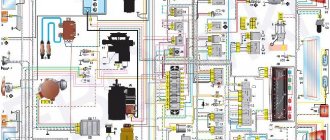
Wiring diagram for the VAZ ignition switch
An equally important nuance is the ignition order. Every car owner should know the ignition procedure so that in the event of a malfunction of the power unit, he can take action to repair or diagnose it. In classic VAZ models, the ignition order is as follows: first, the spark is supplied to the first cylinder, then to the third, fourth and second.
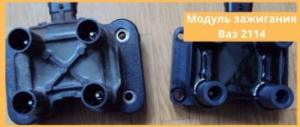
The firing order should be marked on the breaker cover. Number 1 indicates that the wire goes to the spark plug of the first cylinder. If you look at the VAZ ignition module, you will see that there are numbers on its outputs that will help you connect the wires correctly after disconnecting. The ignition order must not be violated.
Instructions for installing a contactless system on the seven
Manipulations for converting the ignition system on a VAZ 2107 from contact to contactless are carried out according to the following principle:
- First, you should turn off the power to the car by disconnecting the minus terminal from the battery.
- Disconnect the armor wires from the spark plugs.
- The spark plugs are unscrewed, after which the crankshaft should be turned with a key set to “36”. This is done in order to set the piston of the 1st cylinder to TDC. To determine that the piston has reached top dead center, use a screwdriver. The notch on the crankshaft pulley must be on the cylinder block.
- The steel latches of the switchgear cover must be snapped off and then removed along with the wires.
- A mark must be placed on the engine valve cover next to the moving contact of the slider.
- All wires are disconnected from the distributor along with a thin tube connecting the device to the carburetor fitting.
- Using a wrench, you need to loosen and unscrew the nut, which is used to press the distributor skirt to the BC.
- The old distributor must be removed, and at the same time pay attention to the gasket so as not to lose it.
- The wires from the coil are disconnected, remembering their locations. The coil mount is unscrewed and the device is dismantled.
- The next step is to install the mounting block.
- Make holes to secure the switch.
- The cover is removed from the new distributor and the gasket is installed. The distributor must be placed in the mounting hole of the cylinder block, and this should be done so that the moving contact is located at the level with the top dead center, which is drawn on the valve cover (the slider should point in the same direction as on the old distributor).
- The distributor skirt is fixed.
- The coil is placed in place of the old device, and terminals with wires from the ignition switch, as well as the tachometer and switch are connected to it.
- The wire from the EB of the first contact must be connected to the coil terminal marked “K”.
- The wire from the fourth contact is connected to terminal “B”.
- The spark plugs are screwed into place, after which the armored wires and the wire suitable for the coil can be connected.
- At the final stage, all that remains is to attach the vacuum tube and proceed to the stage of adjusting the ignition.
This is interesting: Which brake pads are better to choose?
At this point, the installation of electronic ignition on the VAZ 2107 is completed, and before testing the device, you will need to make preliminary adjustments.
Distributor
The sequence of work that must be performed in order to install a set of new parts on a VAZ 2107 does not make much difference. Therefore, we can start by replacing the distributor. Remove the distributor cover to access the slider. To simplify the task of further adjusting the BSZ, you should immediately perform some preparatory measures: installing the distributor slider in a position that will be easy to repeat when installing a new distributor; mark on the block opposite the middle mark on the distributor scale, which is used to adjust the ignition.
Using a 13mm wrench, completely unscrew the nut securing the distributor and then remove it. Disconnect the high voltage wire connecting the ignition coil and the distributor. We install a new non-contact sensor distributor, and you need to set the slider so that it matches the position of the old one. The body of the new distributor needs to be aligned according to the marks, the middle one opposite the one previously left on the engine body. We put on the distributor cover and a set of high voltage wires.
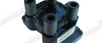
Coil
Next, you need to replace the ignition coil. Using a size 8 wrench, unscrew the nuts securing the wires to the coil contacts. Using a 10mm wrench, unscrew the mount of the coil to the body. Installing a new coil requires special attention - you should take into account the possible discrepancy between the locations of contacts “B” and “K”. For convenience, you can rotate the new electronic coil relative to the fastener, thereby placing the contacts in the same way as on the old one.
Having secured the coil, we connect old wires to its contacts (usually one blue, the other brown), and new ones, with connectors for connecting to the distributor and switch. They usually have the same colors as the standard ones. Typically, in a VAZ 2107, brown wires are connected to contact “K”, and blue wires are connected to “B”. It remains to connect the high-voltage wire that connects the coil and the distributor.
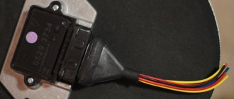
Switch
The last element in the circuit, the presence of which is required by a contactless electronic ignition system, is a switch. The ideal place in which it can be installed in a VAZ 2107 is between the washer reservoir and the left headlight. There is a flat area on which we will install the switch, with the radiator facing the body. Having leaned the switch, we mark the places for drilling holes in the body, through which we fasten it with self-tapping screws; in this case, you need to screw the black (neutral) wire from the connection block under one of the screws.
After completing all the work described above, you should once again carefully check the connection of the wires according to the circuit diagram. If everything is done correctly, you can try to start the engine. Usually there are no problems with this; all that remains is to adjust the ignition to ensure the most efficient operation of the engine.
Checking correct ignition
After completing the steps, it is necessary to check the operation of the ignition system.
To do this you need:
- start the car and drive off;
- Accelerate the car to 50 kilometers per hour, engage fourth gear and sharply press the accelerator pedal. Then, engine detonation will appear, which will decrease (and then disappear altogether) as the speed of the car increases.
There can be two types of problems:
- Engine detonation occurred, but did not disappear as the vehicle speed increased (it is assumed that the ignition was turned on earlier ). In this situation, the switchgear must be turned half or one division to the right.
- Detonation did not occur at all - ignition was delayed . To eliminate this problem, you need to turn the switchgear half or one division to the left .
As you can see, setting the ignition on the VAZ 2101 is quite simple. However, if difficulties or additional questions arise, it is better to contact certified car services for advice.
Basic elements of SZ
Before changing and setting the SZ adjustment, let's get acquainted with its main components:
- Battery and generator unit. The first is used when starting the engine, and the second when it is running.
- Switch or lock. Its purpose is to supply voltage to the electrical network and the vehicle's power supply, as well as to the solenoid relay.
- VAZ ignition coil, used to accumulate energy and convert it into a high-voltage pulse.
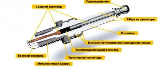
- Candles. Essentially, the spark plug design is a phase insulator mounted on a metal thread, with a conductor located in the center. This conductor is an electrode.
- VAZ distributor - used to distribute a high-voltage pulse along cables that are connected to the spark plugs.
- A high-voltage cable is a wire with reliable insulation. To avoid possible interference in the radio range, the inner conductor can be made in the form of a spiral. Checking the VAZ ignition module usually begins with the diagnosis of high-voltage circuits, as well as spark plugs.
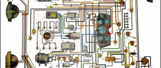
General diagram of the ignition system
Electronic ignition VAZ 2106
Ignition system. 1. Insulator; 2. Ignition coil housing; 3. Insulating paper windings; 4. Primary winding; 5. Secondary winding; 6. Primary winding insulating tube; 7. Output terminal for the end of the primary winding; 8. Contact screw; 9. High voltage terminal; 10. Cover; 11. Terminal “+E” for the output of the beginning of the primary and end of the secondary windings; 12. Central terminal spring; 13. Secondary winding frame; 14. External insulation of the primary winding; 15. Fastening bracket; 16. External magnetic circuit; 17. Core; 18. Contact nut; 19. Spark plug insulator; 20. Rod; 21. Spark plug body; 22. O-ring; 23. Heat sink washer; 24. Central electrode; 25. Side electrode of the spark plug; 26. Distributor roller; 27. Roller oil deflector clutch; 28. Washer; 29. Wire for power supply and distributor; 30. Cover locking spring; 31. Vacuum regulator housing; 32. Diaphragm; 33. Vacuum regulator cover; 34. Nut; 35. Vacuum regulator spring; 36. Vacuum regulator rod; 37. Cam lubrication wick; 38. Ignition timing regulator support plate; 39. Distributor rotor; 40. Side electrode with terminal; 41. Distributor cover; 42. Central electrode with terminal; 43. Angle of the central electrode; 44. Central rotor contact; 45. 5-6 kohm resistor to suppress radio interference; 46. External rotor contact; 47. Ignition timing regulator spring; 48. Centrifugal regulator plate; 49. Weight of ignition timing regulator; 50. Insulating sleeve; 51. Breaker cam; 52. Lever insulating block; 53. Breaker lever; 54. Stand with breaker contacts; 55. Breaker contacts; 56. Movable breaker plate; 57. Capacitor 0.20-0.25 µF; 58. Engine start distributor housing; 59. Bearing of the movable plate of the breaker; 60. Oiler body; 61. Terminal clamp screw; 62. Bearing lock plate; 63. Distributor; 64. Candles; 65. Ignition switch; 66. Ignition coil; 67. Generator; 68. Battery; 69. Sensor-distributor; 70. Switch; 71. Ignition timing; 72. To power supplies; 73. I. Ignition coil; 74. II.Spark plug; 75. III. Ignition distributor; 76. IV. Scheme of the classical system; 77. V. Scheme of operation of the centrifugal ignition timing regulator; 78. VI. Diagram of a contactless system.
Types of SZ on VAZ cars
Before checking the VAZ ignition coil, let's understand the types of SZ.
- Contact system. This type is considered one of the oldest; compared to more modern options, it has many disadvantages. As a rule, most often in such systems the circuit breaker and distributor fail. In addition, over time, the SZ contacts may burn and stick, as a result of which the operation of the power unit may be disrupted.
- Contactless ignition on a VAZ or BSZ is a more modern option made by the developers to ensure higher reliability. In this case, the design eliminates the use of a breaker; instead, a contactless sensor is used. Today, BSZ is used on many cars; quite often VAZ owners install it instead of contact SZ. In general, units of this type require virtually no monitoring, since there are no rubbing elements in such systems. The use of BSZ allows you to achieve optimal engine performance and better combustion of the air mixture.
- Electronic ignition is considered one of the most advanced options. Electronic ignition also almost completely eliminates the use of friction components. In addition, such a system is equipped with various controllers, as well as a control unit. Controllers are used so that the electronic ignition can record the operating parameters of the internal combustion engine, and this, in turn, is necessary for the timely supply of a spark. This SZ ensures the most optimal and correct operation of the power unit. But its main advantage is its efficiency (the author of the video is Roman Romanov).
Ignition Tuning Guide
Adjusting the VAZ ignition is a priority for many of our compatriots. Before setting the VAZ ignition, you need to check the functionality of the spark plugs and wires. Otherwise, if these elements are not working, you will waste time on adjustments, but you will not achieve the desired result.
So, how to do it right:
- First, unscrew the spark plug and close its hole with your finger or rubber plug. Using a special wrench, rotate the crankshaft until the plug flies out of the hole. If you insert your finger, you will feel the air flow pushing it out.
- The crankshaft must be turned until the mark on its pulley is positioned opposite the mark on the timing cover. After this, you can dismantle the distributor cover. At the same time, make sure that the contact of the timing gear rotor is directed towards cylinder 1.
- Unscrew the nut that secures the distributor and turn it upward. The rotor axis should be set parallel to the axis of the power unit. After this, the nut must be tightened.
- Now, using a control light, connect one of its wires to the coil, namely to its low-voltage contact, and connect the second wire to ground, that is, the car body.
- Turn the key in the lock. The distributor must be turned clockwise until the light goes out. If the lamp is not lit at all, then the system does not need adjustment.
- When the lamp goes out, the breaker should be rotated in the opposite direction. When the lamp lights up again, the device must be fixed in place by tightening the nut.
1. Turn the crankshaft with a wrench.
2. Align the marks on the pulley.
Low and high voltage wires:
High voltage wires:
1. High-voltage wires serve to transmit high-voltage current from the ignition coil itself and to each cylinder spark plug.
2. Cars of the Samara family are equipped with high-voltage wires with a distributed resistance of 2550±270 Ohm/m.
3. Under no circumstances try to start a car with a broken high-voltage voltage circuit, that is, to put it simply: The car’s engine does not need to be started with the high-voltage wires removed, as well as with the ignition distributor cap removed. Such actions can lead to failure of the ignition system elements, as well as breakdown of the insulation, so be careful.
4. It is also not recommended to handle or touch high voltage wires when the car engine is in working condition, because this can lead to electrical injury.
Note! When checking high-voltage wires for the presence of a spark, it is recommended to disconnect the wires with the engine turned off, and if the engine is started, the wires should be secured at a distance of 5-10 mm from the mass of the car, and these wires should not be in your hands, even in only if you hold them with a tool!
Low voltage wires:
1. Every person has encountered such wires in his life; they are most often of small thickness and have a very flexible shape, unlike high-voltage wires.
2. And most often, low-voltage wires have a combined color, that is, they come in both red and blue, and have many other colors.
3. A striking example of where the low voltage wires are connected is the same ignition coil, because if you look at it carefully, then on its side you can see two wires, one of which is “red” and the other “blue”. (see photo above)
This is interesting: Why are cheap car seats dangerous for your children?