According to the old “good habit”, the domestic auto industry has always been criticized for the poor quality of components and assemblies. AvtoVAZ suffered the most, since its products were the most widespread, and it was its cars that were in high demand among the population.
VAZ 2112 cars with injection engines have become popular largely due to increased quality
But this does not mean that the manufacturer sat idly by, relying on the shortage of passenger cars in the country. On the contrary, hundreds of related enterprises mastered the production of components so that the plant in Tolyatti could improve the quality of cars.
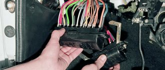
The electrical circuit for the VAZ 2112 consisted of components from more than 30 car suppliers
And this evolutionary path made it possible to choose those that could satisfy both in volume and quality. In particular, the VAZ 2112 wiring diagram for the injector has also undergone repeated transformations, which allows today's owners to experience fewer problems.
Improved components are available only to new models
Note! AvtoVAZ does not carry out vehicle recalls, as is customary abroad. Claims work is carried out with suppliers, and improved components only end up on the conveyor belt, where brand new cars are assembled.
Power units
First of all, significant changes have occurred in the engine compartment, since the VAZ 2111 is equipped with 6 different engines:
- the LADA-21110 model is equipped with an 8-valve 1.5 liter power unit with injectors in the fuel supply system;
- LADA-21111 is equipped with a 1.5 liter carburetor engine;
- LADA-21112 has an 8-valve injection engine increased to 1.6 liters;
- LADA-21113 is equipped with a 16-cavity 1.5 liter engine with an electronic ignition system;
- LADA-21114 is equipped with a 16-cavity 1.6-liter engine with injectors in the fuel supply system;
- LADA-21116 demonstrates the 2.0-liter Opel engine. It is installed on the all-wheel drive VAZ 2111 model, named “Tarzan” - a video about its capabilities can be viewed on the automaker’s website.
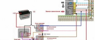
The photo above shows the control diagram of the power unit. It is marked:
- Starting unit (ignition relay – 1, battery – 2 and ignition switch – 3);
- Exhaust gas control unit (pipe – 4 and oxygen sensor – 5);
- Fuel block (high pressure injector – 6, fuel rail – 7, pressure regulators – 8 and idle speed regulators – 9);
- Air filter housing (10);
- Diagnostic connector (11).
For reference: the “brains” of the injection and contactless ignition system are the controller and ECM, which work together with the standard anti-theft system. Its role is played by the immobilizer (no. 17 in the diagram).
Operating mode
The following two tabs change content below.
All my life I have been surrounded by cars! First, in the village, already in the first grade, I was rushing around on a tractor through the fields, then there was JAVA, then a penny. Now I am a third-year student at the Polytechnic Faculty of Automotive Engineering. I work part-time as a car mechanic and help repair cars for all my friends.
On VAZ-2112 cars, the operating temperature of the engine is about 89 degrees, the thermostat begins to open at 85, and the fan, with standard settings, starts at 105 and turns off at 97. We talked in more detail about the cooling system diagram of the VAZ-2112 in this material: complete diagram of the cooling system of the VAZ-2112.
Electrical equipment
Depending on the installed power unit, the electrical wiring of the VAZ 2111 also changes.
This is due to the fact that the car uses:
- Fuel injection systems;
- Contactless ignition;
- The transverse location of the power unit in the engine compartment also affects the wiring.
After all, the changed location of the motor alone forced the designers to develop:
- Another layout of wiring attachment points in the engine compartment;
- Form wiring harnesses differently for close groups of devices and sensors.
Applicable controllers
The engine is controlled using an electronic controller. And for each modification, the manufacturer installed a specific model, which may not coincide with the factory documentation.
The automaker installed the following controllers on all cars:
- GM model (2111-1411020-20);
- model “January 4.1” (2111-1411020-22);
- model M 1.5.4 (111-1411020-00);
- model “January 5.1” (2111-1411020-61);
- model “January 5.1.1” (2111-1411020-71);
- model MP 7.0 (2111-1411020-40).
Tip: If you service the car yourself, be sure to use the diagram for a specific controller.
An electrical circuit is used to connect all electrical appliances and equipment in a vehicle. If any of its elements fails, this may affect the functioning of the car as a whole. You can learn more about what the electrical circuit of a VAZ 2111 injector 8 valves is and what malfunctions are typical for it from this material.
What's better
One of the questions that 2110 owners ask is which headlights are best to choose for this vehicle. For the VAZ 2110, only Bosch and Kirzhach headlights are standard. If we consider the secondary market, what headlights are suitable for a foreign car?
This car configuration uses the following types of products:
- in the form of a monoblock;
- using lenses;
- modular;
- black;
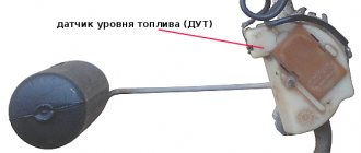
- chrome plated;
- tinted.
In order not to be confused about which base is in the VAZ headlights, you can refer to the manufacturer’s documentation. Cars have a standard H1 base. When choosing new blocks, you need to focus on this feature.
What is included in the electrical circuit?
First, we suggest you understand what systems and components are used in the wiring diagram.
Its main elements:
- Battery. This device is designed to ensure normal engine starting, as well as power supply to electrical appliances and equipment when the engine is not running. If the battery is discharged, you will not be able to start the engine with the key; you will need to either try to start it with a pusher, or “light it”.
- Starter. The purpose of this unit is to provide the ignition system with a high-voltage pulse necessary to ignite the combustible mixture in the internal combustion engine cylinders.
- A generator is one of the main components of any electrical system. This unit is necessary to power the electrical devices and instruments of the vehicle while it is moving. In addition, the generator allows you to charge the battery, replenishing its charge that was used to start the engine.
- Ignition switch.
- Mounting block with fuses. The purpose of fuses cannot be underestimated - these devices are used to protect electrical circuits of cars. If voltage surges occur in the electrical system of the engine injector 16 valves, then the fuse will be the first to fail, thus protecting the equipment from breakdown (the author of the video is the Autoelectrics HF channel).
But these are only the main components of the system; as for the complete electrical circuit, it includes various components and systems:
- connecting the starter unit;
- contactless ignition system;
- ignition switch connection diagram;
- lighting system, including optics for low and high beams, brake lights, side lights, fog lights, turn signals, as well as lighting in the car interior;
- activation system for windshield wipers, as well as windshield and rear window washers;
- sound signal activation circuit;
- power window activation system;
- activation of the cooling system ventilator;
- luggage compartment lock;
- node ;
- instrument panel, which displays all the main instruments of the car, the status of sensors, speedometer, tachometer;
- automatic stove control system;
- generator unit connections;
- power unit control.
Common faults
As you can see, in general, a 16-valve engine is a rather complex system. Accordingly, there are also enough breakdowns in its operation; all of them can be divided into several groups. For example, if you have suspicions about the functionality of the spark plugs, and they turned out to be working, then you need to check the operation of the ignition coil and high-voltage cables. As practice shows, breakdowns in the wires can also lead to incorrect operation of the ignition system. Failure of one or another element of the electrical network can be a consequence of either a breakdown of the device itself or a failure of the generator unit or battery.
Most often, car owners are faced with the problem of battery failure, so let’s look at the main malfunctions characteristic of this device:
- a short circuit has occurred between the electrodes of the device;
- damage to the plates located inside;
- the appearance of cracks and other mechanical damage on the battery case, as well as shedding of the plates, which can lead to leakage of electrolyte;
- oxidation of the battery terminals, this problem can be solved by stripping.
All these faults ultimately lead to battery discharge. If we talk about the reasons that caused these problems, then most likely they all lie in incorrect operation, of course, if the battery life is high and has not yet expired. Much less often, the malfunction lies in a manufacturing defect, but this happens infrequently.
To prevent malfunctions in the operation of the battery, the following rules should be taken into account during operation:
- Firstly, the device must be securely fixed at the landing site. If the battery is not secured securely, this can lead to constant vibration, which can subsequently cause cracks in the case.
- Operation of the car and, accordingly, the use of the electrical network is allowed only when using a working generator. If the alternator is faulty or its belt tension is weak, it will ultimately lead to battery discharge.
- If the contact at the device terminal is poor, this can lead to its oxidation and destruction.
- Cranking the starter for a long time when trying to start the engine also contributes to battery discharge. This problem especially often manifests itself in cold weather, when the battery electrolytes are less mobile, and the driver has to turn the starter longer to start it (the author of the video is Vyacheslav Kravchenko).
Depending on the type and manufacturer, the battery life can range from three to five years. However, the service life may be shorter if the battery is used intensively and in harsh conditions. One way or another, the consequence of battery discharge is always the same - the device will not be able to crank the starter to start the engine, as well as power the devices and equipment of the car as a whole. If the diagnostics show that the battery is working normally, the cause of the malfunction may lie in the performance of the generator.
Its design as a whole is more complex; accordingly, this unit has a lot of faults:
- erasing of brushes due to their wear;
- voltage regulator relay failure;
- failure of the diode bridge;
- bearing wear, which is accompanied by a hum when the generator operates;
- wear of slip rings;
- damage or wear of pulley teeth;
- short circuit in the stator winding;
- damage to the charging circuit wiring;
- broken or worn alternator belt.
Malfunctions in the operation of the unit can be determined by diagnostics using a multimeter. As for repairs, you can do it yourself. We have previously described the procedure for repairing a generator using the VAZ 2114 model as an example in this one; in the case of the VAZ 2111 it looks similar.
As for other malfunctions in the operation of the electrical circuit, there may be several reasons:
- failure of the device itself;
- fuse blown caused by a short circuit (before replacing the fuse, it is necessary to determine the cause of the short circuit);
- electrical circuit breakage, the problem is solved by replacing the wire;
- oxidation of contacts on device terminals (video author - Ramanych channel).
conclusions
The fan switch on sensor on the 16-valve VAZ-2112 engine is located on the cylinder head near the thermostat. So, its breakdown can lead to the fan stopping working and the engine not cooling properly, which in turn will lead to it boiling, and even more complex malfunctions may occur.
Car : VAZ-2112. Asks : Kirillov Igor. The essence of the question : The cooling fan does not work, does not turn on at all, what should I do?
Hello! The fan on my VAZ-2112 stopped turning on. It so happened that the car simply boiled in a traffic jam, so I realized that the fan simply did not work. Tell me what could be the reason?
Prevention measures
To prevent problems in the operation of electrical equipment, it is necessary to follow certain preventive measures, in particular:
- Charge the battery at least once a year using a charger. This is especially important to do before winter, as well as in cases where you plan to leave the car in a garage or parking lot for a long time. If the car will be parked, it is better to remove the battery altogether and charge it before installation. The battery also needs to be serviced, checking at least twice a year for the presence of electrolyte in the system and the charge of the device with the engine running and off.
- Never use low quality fuses. The same applies to the use of homemade fuses in the form of a wire or coin. Drivers usually install homemade devices if a certain fuse has failed and there is nothing to replace it with. If you are faced with the need for replacement, then, of course, a homemade version can also be used, but only in order to get to the nearest store and replace it with a normal fuse. Using homemade products can lead to short circuits and even fire.
- Always install only high-quality devices and equipment on your car - from the generator unit to the light bulbs in the dashboard. If the equipment is of low quality, its service life will not be as long, especially since its use over time can lead to inconvenience for the driver.
- If there are problems with the operation of the equipment, they must be resolved immediately. For example, you saw that the Check Engine indicator appeared on the control panel - we recommend that you check the engine as soon as possible. To obtain more accurate results, use computer diagnostics - it will help determine which node needs attention first. It should be noted that the appearance of this light is quite often due to problems in the operation of certain sensors. And their performance, in turn, can be impaired as a result of broken wiring or oxidation of contacts on the connectors. In this case, it is not necessary to immediately change the sensor - you need to change the wire and clean the contact - it is quite possible that this will solve the problem.
- If there are short circuits in the electrical circuit, they must be eliminated, since they can lead to breakdown of the electrical equipment as a whole.
- Never forget that all network elements must be reliably sealed, especially take this into account when installing equipment and wiring yourself. Auto electrical appliances and their circuits should not be affected by moisture or other factors.
This free collection contains all the necessary documentation for the electrical equipment of the VAZ-2111 car - the circuit itself, the heating system, headlight cleaner, electronic engine control module and fuse box. The VAZ 2111 is the first station wagon in the line of front-wheel drive cars, which is a modernized concept of the rear-wheel drive VAZ 2104. In it, the wiring diagram for the injector and a number of other components have undergone changes as part of the change in concept. Schemes can be viewed here.
Operating mode
On VAZ-2112 cars, the operating temperature of the engine is about 89 degrees, the thermostat begins to open at 85, and the fan, with standard settings, starts at 105 and turns off at 97. We talked in more detail about the cooling system diagram of the VAZ-2112 in this material: complete diagram of the cooling system of the VAZ-2112.
Causes of malfunction
If the radiator fan refuses to start, check the items in the following order:
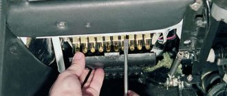
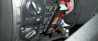
- Fuse - Check this fuse element for continuity in the fuse block. It is located there under the number F7 and has a rating of 20 amperes.
Fan fuse - yellow F7. (editing machine mounting block, 124 engine)
The relay is located under the number “4”.
The sensor should be checked and replaced if necessary.
You can try to repair the electric motor.
When all of the above methods did not bring the desired result, you need to look for the reason only in the wiring, “ringing” them one by one. Perhaps there was a break or break in the wire somewhere.
Source
Electrical diagram of VAZ-2111 carburetor
1. block headlight; 2. front brake pad wear sensors; 3. fan motor activation sensor; 4. electric motor of the engine cooling system fan; 5. sound signal; 6. generator: 7. oil level sensor; 8. carburetor solenoid valve control unit; 9. heater controller; 10. recirculation valve switch; 11. illumination lamp for heater control levers; 12. switch; 13. carburetor limit switch; 14. oil pressure warning lamp sensor; 15. spark plugs; 16. carburetor solenoid valve; 17. coolant temperature indicator sensor; 18. ignition distributor sensor; 19. ignition coil; 20. VAZ-2111 starter; 21. heater fan electric motor; 22. additional resistor for the heater electric motor; 23. speed sensor; 24. reverse light switch; 25. micromotor gearbox for heater damper drive; 26. recirculation valve; 27. brake fluid level sensor; 28. blocks for connecting the rear window washer motor; 29. battery; 30. windshield washer motor; 31. washer fluid level sensor; 32. coolant level sensor; 33. windshield wiper gearmotor; 34. mounting block: 35. blocks for connecting the warning light harness; 36. outdoor lighting switch; 37. instrument cluster; 38. rear fog light switch; 39. fog light indicator lamp; 40. indicator lamp for heated rear window; 41. watch; 42. rear window heating switch; 43. steering column switch; 44. block for switching wires when installing headlights of a different type; 45. instrument lighting regulator; 46. ignition switch; 47. connectors for connecting the headlight cleaner wiring harness; 48. socket for a portable lamp; 49. lamp for individual interior lighting; 50. brake light switch; 51. interior lamp; 52. on-board control system unit; 53. fuel level indicator sensor; 54. hazard warning switch VAZ-2111; 55. driver's seat belt sensor; 56. cigarette lighter; 57. ashtray illumination lamp; 58. glove compartment lamp switch; 59. block for connecting the on-board computer; 60. glove box lighting lamp; 61. side direction indicators; 62. switches in the front door pillars; 63. switches in the rear door pillars; 64. parking brake warning lamp switch; 65. trunk lighting; 66. temperature sensor for the heating system; 67. external rear lights; 68. internal rear lights; 69. license plate lights; 70. rear window heating element; 71. block for connecting an additional brake light for VAZ 2111.
Wiring diagram for VAZ 2111 injector
- 1 - block headlight
- 2 — front brake pad wear sensors
- 3 - sound signal
- 4 - cooling fan
- 5 - reverse light switch
- 6 - battery
- 7 - generator
- 8 - oil pressure warning lamp sensor
- 9 - oil level sensor
- 10 - spark plugs
- 11 — nozzles
- 12 — idle speed regulator
- 13 — blocks of the electronic control unit
- 14 - throttle position sensor
- 15 - crankshaft position sensor
- 16 — ignition module
- 17 - coolant temperature indicator sensor (for instrument cluster)
- 18 - starter
- 19 — diagnostic block
- 20 - coolant temperature sensor (for engine management system)
- 21 - speed sensor
- 22 - fuel pump activation relay
- 23, 35, 39 - fuses
- 24 - electric fuel pump
- 25 — micromotor gearbox for heater damper drive
- 26 - recirculation valve
- 27 - heater fan
- 28 - windshield washer pump
- 29 — washer fluid level sensor
- 30 - brake fluid level sensor
- 31 - coolant level sensor
- 32 — windshield wiper gearmotor
- 33 - additional heater fan resistor
- 34 - injection system power supply relay
- 36 — adsorber purge valve
- 37 - mass air flow sensor
- 38 — relay for turning on the cooling fan
- 40 — external lighting switch
- 41 - knock sensor
- 42 — oxygen concentration sensor (heated lambda probe)
- 42* — CO potentiometer (installed on cars running on leaded gasoline; in this case, an oxygen concentration sensor is not installed)
- 43 - fog light indicator lamp
- 44 - indicator lamp for heated rear window
- 45 - fog light switch
- 46 — rear window heating switch
- 47 - instrument cluster
- 48 — mounting block
- 49 - fuel level sensor
- 50 - ignition switch
- 51 — instrument backlight brightness control
- 52 - steering column switch
- 53 — backlight lamp for heater control levers
- 54 - hazard switch
- 55 — electronic heater control unit; 56 - recirculation valve switch
- 57 — display unit of the on-board control system
- 58 — side direction indicators
- 59 - temperature sensor for the heating system
- 60 — interior lamp
- 61 — front interior lamp
- 62 — socket for a portable lamp
- 63 - electronic watch
- 64 — switches in the front door pillars
- 65 — switches in the rear door pillars
- 66 — glove box lighting lamp
- 67 — glove box lighting switch
- 68 - cigarette lighter
- 69 — ashtray lighting lamp
- 70 - brake light switch
- 71 — rear window heating element
- 72 — external rear lights
- 73 — internal rear lights
- 74 — license plate lamps
- 75 — trunk lighting lamp.
VAZ 2111 engine control circuit
- 1 — fragment of the mounting block.
- 2 — electric fan of the engine cooling system.
- 3 - status indicator of the car anti-theft system.
- 4 — control unit of the automobile anti-theft system.
- 5 — coolant temperature sensor.
- 6 — air flow sensor.
- 7 - throttle pipe.
- 8 - block connected to the throttle position sensor.
- 9 - block connected to the idle speed regulator.
- 10 — VAZ 2111 controller.
- 11 - block connected to the air conditioner wiring harness.
- 12 — oxygen sensor.
- 13 - knock sensor.
- 14 - crankshaft position sensor.
- 15 - speed sensor.
- 16 - adsorber.
- 17 - battery.
- 18 - main relay.
- 19 - block connected to the wiring harness of the anti-lock brake system.
- 20 — diagnostic block.
- 21 - main relay circuit protection fuse.
- 22 - controller protection fuse.
- 23 - fuse for protecting the electric fuel pump and its relay.
- 24 - relay for turning on the electric fuel pump.
- 25 — relay for turning on the electric fan.
- 26, 27 — blocks connected to the instrument panel wiring harness.
- 28 — ignition module.
- 29 - electric fuel pump with fuel level sensor.
- 30 - spark plugs.
- 31 - injectors.
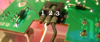
Purpose of the plugs in block 26: 1 - to the low-voltage input of the tachometer in the instrument cluster; 3 - to the “Engine fault” lamp in the instrument cluster (from the controller); 4 - to the lamp switch located on the driver's door pillar; 5 - to the “Engine fault” lamp in the instrument cluster (supply “+” power); 6 — to the trip computer (fuel consumption signal); 7 - to the instrument cluster (vehicle speed signal 2111); 8 - to terminal “15” of the ignition switch (plug 4 of the switch block).
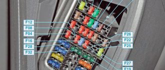
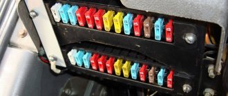
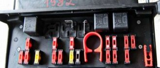
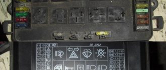
VAZ-2111 fuse block diagram
- 1 - ignition module
- 2 — speed, air flow, heating sensors
- 3 - fuel relays, pump, injectors
- 4 - fan
- 5 - fuel pump
- 6 - ignition
- F1 5 Lighting lamps: license plates, instruments, dimensions on the dashboard, left dimensions, trunk lighting
- F2 7.5 Low beam in the left headlight
- F3 10 High beam in the left headlight
- F4 10 Right front fog lamp
- F5 30 Door windows
- F6 15 Portable lamp, cigarette lighter
- F7 20 Radiator fan, sound signal
- F8 20 Heated rear window
- F9 20 Windshield washer and wiper
- F10 20 Reserve
- F11 5 Clearance on the right side
- F12 7.5 Low beam in the right headlight
- F13 10 High beam in the right headlight
Being a body shortened to 4170 mm in comparison with the VAZ 2110, the new model retains all the qualities of a hatchback. Reducing the base had a positive effect on the car's handling, which made it a favorite among car enthusiasts in the domestic auto industry.
Historical reference
The car was equipped with a fuel injection distribution system that complies with the requirements of exhaust gas toxicity standards:
- The 16-valve power unit was equipped with an electronic system based on the M7.9.7 controller and complied with EURO 3;
- The 8-valve power unit complied with EURO 2 standards.
For reference: for brevity, the engine control system with distributed fuel injection is referred to in the diagrams as an abbreviation - SUD. For the EURO 3 engine it is equipped with a solenoid valve for purge the adsorber - in the diagram under No. 13.
EURO 3 - 16 valve version
The presented diagram shows the main components and sensors, thanks to which the control system organized the supply of the air-fuel mixture to the cylinders:
- The main components are the ignition coil, fuel injectors, controller and main relay (indicated in the diagram as numbers 1,2,3 and 4);
- A larger group of sensors includes several systems at once: power supply, cooling, air supply, engine operation, etc.
Control systems for monitoring the operation of the power unit include:
- throttle position sensor (No. 12);
- knock sensor (No. 18);
- diagnostic oxygen sensor (No. 16);
- crankshaft position sensor (No. 19);
- coolant temperature sensor (No. 13);
- immobilizer control unit (No. 20);
- coolant temperature indicator sensor (No. 26).
Visual surveillance systems include:
- immobilizer status indicator (No. 21);
- vehicle speed sensor (No. 23);
- oil pressure warning lamp sensor (No. 25);
- fuel level sensor (No. 24).
In addition, the VAZ 21124 wiring diagram also contains built-in protection elements:
- Main relay fuse (No. 5);
- Relay and fuse for electric cooling fan (No. 6 and 7);
- Fuel pump relay and fuse (No. 8 and 9);
For reference: G1, G2 indicated in the diagram are grounding points, A – ABS system block, B – diagnostic connector.
EURO 2 compliant power unit
The electronic content of the car is similar to the 16-valve version:
- single controller for power units M7.9.7
- general factory instructions for cars with different power units.
In addition to the different markings of the sensors, the car circuits are identical with the exception of the solenoid valve for purge the adsorber, which is equipped with EURO 3 engines.
Comments and reviews
Ignition circuit and engine control system We provide control circuits for the following internal combustion engines: - January 5. VAZ engine control system and
VAZ Tarzan. It’s good that the cooperation of car enthusiasts and their timely tips help save time, money and nerves when the car needs repairs.
VAZ Tarzan.
You need to check whether the battery terminals are tightly connected and whether they are oxidized. Turn signals Turn signal lamps 1, 5 and 6 are activated by switch 7. If independent repair or tuning concerns the car’s electrical system, then you cannot do without diagrams of such equipment. On x with engines there is a wiring harness for the fuel injection system, installed instead of the engine ignition system harness, see.
Actuators, central locking unit and one limit switch It would seem that everything is simple here.
High beam indicator lamp F14 10 Left fog lamp F15 20 Electric seat heating. Fuse diagram for VAZ 2110, 2111, 2112 - instructions