07/17/2021 13,041 VAZ 2110
Author: Ivan Baranov
Any modern car is equipped with many different sensors that allow the driver to know about the condition and performance of certain components. And the VAZ 2110 car is no exception; in this article we will talk about what sensors are used in it and what their location is.
As you know, the VAZ 2110 injector with 8 or 16 valves is significantly superior to the carburetor version in many ways. At least because in this case the supply of gasoline, as well as the combustible mixture, is regulated by electronics. Accordingly, the use of electronics implies the use of many different regulators and controllers. Their breakdown can lead to certain consequences, so the car owner should always know what certain regulators are responsible for. Below we consider almost all VAZ sensors that are in the top ten.
[Hide]
A little history
The VAZ 2110 was produced from the end of the 20th century until the middle of the first decade of the 21st century.
During its existence, the top ten managed to gain a huge number of fans and underwent a large number of changes. The tenth VAZ family was initially equipped with 8-valve carburetor engines that had common roots from the G8 engines. Time moved forward and AvtoVAZ needed to develop further, and at the end of the 90s, an injection engine was installed on the top ten for the first time, which was distinguished not only by a new injection system, but also by the number of valves; some new engines received a doubled number of valves from 8- mi to 16.
To operate an engine with an injection system, you need a huge number of different sensors responsible for the operation of the internal combustion engine, and the VAZ 2110 is no exception; the dozens of injection engines have many different sensors installed that ensure correct and smooth operation of the engine.
In this article we will talk about VAZ 2110-12 sensors, their symptoms of malfunction and installation locations.
Mass air flow sensor (MAF)
It is one of the most important sensors. The mass air flow sensor is responsible for the formation of the air-fuel mixture. It measures the volume of air supplied to the intake receiver and transmits the readings to the electronic engine control unit, which in turn supplies the right amount of fuel in relation to air. The failure of this sensor affects many different functions of the internal combustion engine.
It should be noted that the “CheckEngine” lamp will light up only if the sensor fails completely. Most often, the sensor undergoes aging, but very rarely fails completely. You can read how to check this sensor in our article.
Signs of malfunction:
- Increased fuel consumption;
- Uneven idle speed;
- Difficulty starting the internal combustion engine;
- Loss of dynamics;
- Jerks when moving;
Speed sensor
This sensor is designed to transmit readings to the engine ECU about the speed of the vehicle. It is involved in adjusting the engine speed when driving, namely, if the car is rolling in neutral, you will notice that the speed is slightly higher than the idle speed when the car is standing still. The DS is also responsible for the performance of the speedometer and odometer.
Signs of malfunction:
- Inoperative speedometer or odometer;
- There are no increased speeds when driving in neutral gear;
Symptoms of a problem
Now let’s look at the malfunctions of the oxygen sensor themselves. In most cases, the car itself will indicate problems with the lambda probe.
A malfunctioning probe will affect:
- dynamics of speed gain;
- unstable operation of the power plant;
- the engine speed at idle will fluctuate greatly;
- fuel consumption will increase significantly.
If all this begins to appear, then the lambda probe is often the culprit, and you first need to pay attention to it.
Well, the “Check Engine” indicator lamp will definitely light up, although it will be possible to find out that the lambda probe was the reason for the lighting of this lamp only after diagnosing the electronic unit with a scanner.
Also read how to check how to check the lambda probe.
Basic malfunctions.
As for the malfunctions of this sensor themselves, they can be conditionally divided into external and internal.
External faults.
There are only two of them - a break in the wiring going to the element (although this malfunction does not affect the sensor itself, it affects its performance), and a strong blow, which led to damage to the housing and destruction of its internal elements.
Both of these malfunctions often occur due to aggressive use of the car, for example, frequent active off-road driving.
Internal faults.
There are several more:
- Violation of the tightness of the sensor housing, which led to the penetration of air or exhaust gases into the lambda probe;
- Significant layering of combustion products on the working surfaces of the sensor, due to which platinum is not able to capture oxygen molecules. Most often occurs due to the use of low quality fuel;
- Natural aging of the sensor. He works in an aggressive environment, which gradually reduces his performance until he completely stops performing his functions;
- Exposure to very high temperatures can cause the sensor to overheat and become unusable. Most often it occurs due to a malfunction of the fuel system or unqualified modification of the engine.
External malfunctions, as well as depressurization of the housing, immediately affect the operation of the motor.
But internal faults have their impact on the performance of the power plant gradually, as the problem worsens.
In some situations, cleaning the lambda probe can save the situation; you can find out more about this here.
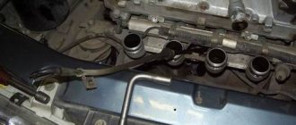
Coolant temperature sensor (DTOZH)
The DTOZH is installed in the thermostat housing and transmits readings to the ECU about the temperature of the engine coolant. Based on these readings, the engine control unit increases or decreases engine speed for more stable operation of the internal combustion engine. The operation of this sensor is noticeable on a cold engine; when starting the engine in the cold season, you can notice increased speed, which decreases over time as the engine warms up to operating temperature.
Signs of malfunction:
- Increased fuel consumption;
- Poor starting on a cold engine;
- Lack of warm-up speeds;
Main set of sensors for 16-valve VAZ-2112 engines
The ECU must control many parameters at once. The most important information will be the position of the crankshaft. You can turn off all sensors except the DPKV, and this will not lead to the engine stopping.
Sensors connected to the ECU
Let's list all the elements one by one:
- 15 – DTOZH. A resistor screwed into the thermostat housing. The temperature of the antifreeze is determined;
- 17 – DPRV, also known as DF (phase sensor). The operating principle is the Hall effect. The position of the camshaft is controlled. Check it out here.;
- 20 – TPS. Resistor fixed to the throttle assembly 19. The angle of deflection of the throttle valve is measured;
- 21 – Mass air flow sensor. Sensor connected to the filter housing. Controls air flow; the main signs of its malfunction are discussed here;
- 22 – IAC. Not a sensor, but a regulator (electromagnet). Used in idle mode. About its testing and diagnostics here. About replacing the IAC here.;
- 24 – lambda probe or oxygen sensor (see above);
- 25 – speed sensor. Fixed in the gearbox slot. Operating principle – Hall effect;
- 26 – DPKV. Electromagnetic sensor. The position of the crankshaft is controlled;
- 27 – DD (knock sensor). A piezoelectric element mounted on the outer wall of the cylinder block.
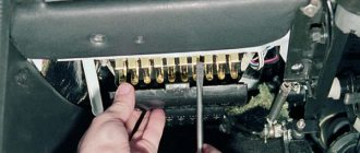
Let's take a look at how all the elements look in real life. Shown are pictures of VAZ-2112 sensors (16-valve internal combustion engine).
Each element will be easy to find under the hood
Everything said above is true for two engines at once - for units 21124 and 21120 (1.6 and 1.5 l).
You cannot unscrew the DTOZH sensor without draining the coolant. And to disconnect the sensor means to disconnect the connector, but not to dismantle the sensor itself.
Where is which sensor located - engine compartment diagram
Let's look at another picture.
Engine compartment and engine 21124
It is important to understand where the following elements are located:
- DPKV;
- Lambda probe;
- Speed sensor;
- RXX;
- TPDZ;
- DMRV;
- DTOZH.
The location of the phase sensor is indicated in the previous chapter.
Never unscrew the speed sensor. It will be difficult to install it in a way that maintains a seal.
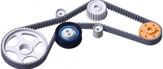
Crankshaft position sensor (CPS)
DPKV is a sensor that counts crankshaft revolutions. Just like most sensors, it participates in the formation of the fuel mixture. If it malfunctions, the car will not start.
The sensor is installed on the rear of the engine under the oil filter. Works in tandem with the crankshaft pulley (generator drive).
Signs of malfunction:
- The car does not start (no spark);
- Jerks when moving;
- Spontaneous engine stop;
Phase sensor (PF)
This sensor is necessary for counting camshaft revolutions; its functions are similar to those of the DPKV. Designed for phased fuel injection; without this sensor, the internal combustion engine will operate in emergency mode and the fuel supply will switch to pairwise mode.
It is installed under the timing cover on 16-valve engines, and on 8-valve engines on the end of the cylinder head on top of the thermostat.
Signs of malfunction:
- Increased fuel consumption;
- Unstable work at XX;
- Loss of dynamics;
Other control devices
The remaining sensors are also connected to the controller and perform important functions. Failure of any of them leads to an increase in fuel consumption, loss of acceleration dynamics or unstable operation of the power unit. Here is their list:
- throttle position detector;
- knock sensor;
- speed meter;
- oxygen sensor;
- phase detector.
The element that determines the angle of rotation of the throttle valve is installed on its body and is directly connected to the axis. The task is to facilitate the supply of excess fuel to the cylinders when the accelerator pedal is pressed sharply. The principle of operation is similar to the accelerator pump in a carburetor, only of the electronic type. The device often fails, especially after washing the engine.
The knock sensor located on the front side of the cylinder block functions much more reliably. Unlike other devices, it generates a signal independently, acting on the principle of a piezoelectric element. The stronger the detonation flashes in the cylinders, the more voltage is supplied to the controller, and it regulates the ignition angle, trying to extinguish detonation. If necessary, change with a wrench.
The oxygen sensor (otherwise known as a lambda probe) monitors the content of free oxygen in the exhaust gases, indicating that the fuel mixture is enriched or lean. Participates in the formation of this mixture and is very reliable in operation. It is afraid of leaded fuel and quickly breaks down when used. It is located in the first part of the exhaust tract, at the convergence of the exhaust manifolds.
The speed meter also works on the principle of a Hall sensor and takes readings from the speedometer drive shaft located near the gearbox. The task is to transmit information about the speed of the car to the processor.
Additional information about the operation of the timing belt is transmitted to the controller by a device that determines the phases. It is installed on VAZ-2112 cars with 16 valves in the upper part of the cylinder head. This device tells you when the fuel valves are opening by monitoring the position of the intake camshaft. This helps to synchronize the complex process of gas distribution and injection of the fuel mixture at the right time.
Idle air control (IAC)
This sensor is installed on the throttle valve and regulates the air supply when the car is running at idle. In other operating modes of the internal combustion engine, the idle air regulator is not involved. The sensor performs mechanical functions, so if it malfunctions, the “CheckEngine” warning light does not light up.
If the regulator breaks down, you can wash it and try installing it again. If washing does not help, the sensor must be replaced with a new one.
Signs of malfunction:
- Unstable idle;
- The engine stalls when coasting;
- Difficulty starting the engine;
- Low speed XX;
Throttle Position Sensor (TPS)
TPS is designed to transmit indications about the position of the valve in the throttle assembly. The received readings are transmitted to the ECU for further regulation of the fuel mixture. This sensor fails quite often. Located on the throttle valve above the IAC.
The sensor cannot be repaired and if it breaks, it is replaced with a new one.
Signs of malfunction:
- Spontaneous increase and decrease in speed;
- Difficulty starting the engine;
- Increased fuel consumption;
- Low speed XX;
Oxygen sensor (OS)
The VAZ 2110 oxygen sensor is installed in the exhaust manifold. The DC measures the exhaust gases and uses their readings to determine the ratio in which the fuel mixture is formed. If the readings exceed the permissible values, the ECU adjusts the air-fuel mixture in such an amount that the exhaust gases do not exceed the permissible values.
Signs of malfunction:
- Increased fuel consumption;
- Loss of vehicle dynamics;
- Black smoke when driving at high speeds;
Oxygen sensor or lambda probe VAZ 2110
The VAZ 2110 injector oxygen sensor or lambda probe is installed on the exhaust manifold. The purpose of the device is to monitor the composition of exhaust gases and the presence of oxygen there. This information helps the electronic control unit (ECU) adjust the composition of the working mixture, which not only helps burn fuel more efficiently, but also improves the environmental friendliness of the exhaust. When using leaded gasoline, the oxygen sensor does not work correctly. Photo of the sensor below.
If the sensor fails, it causes increased fuel consumption and increased emissions. The most interesting thing is that if there are already two oxygen sensors or lambda probes in the exhaust system of the catalyst, there are already two oxygen sensors or lambda probes. The second is placed behind the catalytic converter, this helps make the car even more environmentally friendly.
Knock sensor (DS)
This sensor is installed on the engine block between cylinders 2 and 3. Serves to catch detonations in the engine. Based on the detonation readings from the DD, the electronic control unit forms the amount of fuel supplied to the combustion chamber.
Signs of malfunction:
- Loss of vehicle dynamics;
- Unstable idle;
- Jerking when moving;
The fuel-injected 8-valve VAZ 2110 has a wide variety of sensors. Each of them has its own important function, the termination of which can lead to certain consequences.
Mass air flow sensor on VAZ 2110
It is obvious that the injector has long surpassed the carburetor in all respects. If only for the reason that in injectors the electronics are responsible for supplying fuel and air-fuel mixture to the cylinders. Efficiency, economy and a number of other advantages have literally displaced the carburetor from its once leading position.
The presence of a large number of electronics provides an abundant number of sensors. We will talk about some of them today:
- Air regulator sensor;
- Fan switch sensor;
- Crankshaft sensor;
- Coolant temperature sensor;
- Speed sensor;
- Phase sensor.
Now let's look at them in more detail.
Knock sensor VAZ 2110
The VAZ 2110 injector knock sensor is located on the cylinder block. The task of this device is to transmit a signal to the ECU about detonation. The electronic control unit, in accordance with software algorithms, rearranges the operation of the engine (changes the ignition timing) in order to reduce the negative impact of detonation. Initially, the VAZ 2110 was equipped with a resonant sensor (piezoelectric), but then a more advanced broadband sensor (piezoceramic). A photo of both types of sensors is below.
Actually, the stronger the detonation, the stronger the sensor produces AC voltage to the ECU. You can check the functionality of this sensor quite simply; simply knock lightly on the core of the sensor. In this case, it is necessary to connect a tester to the sensor terminals, which should record voltage surges.
Air regulator
The ECM is the electronic engine control system. And she needs to know how much air to supply for the amount of fuel supplied. These two parameters are closely interrelated because they allow you to create an optimal air-fuel mixture.
Having determined the amount of air, the system determines the required volume of gasoline. The air sensor is responsible for the suction volumes. The disadvantages of this device include:
- Due to exposure to moisture, performance is impaired;
- At low speeds, the sensor produces increased readings;
- The device cannot operate normally when idling;
- Problems may arise when starting the engine;
- After increased power mode, the engine may stop abruptly;
- Fuel consumption increases.
How does this sensor work? Let's try to figure it out.
- The regulator design includes three sensitive components that are installed in the air flow. One of the elements determines the temperature of the intake air, and the other two heat up to the required levels.
- Air flow is determined by measuring the power of electricity to maintain the required temperature.
- The regulator has a mesh that is mounted in the air flow.
- All this allows you to transfer information to controllers, which, in turn, enable certain modes to change or maintain loads.
Article on the topic: Installing engine protection on a VAZ 2109
Fan sensor
This device is designed to activate the fan that cools the power unit. This sensor on the VAZ 2110 has strengths:
- It is very reliable because it includes a solid filler in its design. At elevated temperatures it expands;
- The design also provides for a spring-loaded lever, which prevents defects from occurring;
- The sensor does not allow sparks to occur;
- By purchasing a high-quality regulator, you can forget about replacing it for many years.
Crankshaft regulator
As you understand, the location of all sensors on the 8-valve injection VAZ 2110 is different, but they are all combined into a single system. The crankshaft sensor is no exception.
Regulator
Through the operation of this device, the system determines when to supply fuel and a spark to ignite the mixture. In fact, the design of the unit is presented in the form of a magnet and a coil of thin wire.
Its strengths include:
- Works for a long time and efficiently even under high loads;
- Functions in conjunction with the crankshaft pulley;
- If the sensor breaks down, the engine stops working or limits the speed to no more than 3500 revolutions.
The device is located on the oil pump, literally at the very top of the pulley teeth. To be more precise, 1 millimeter from them.
Coolant temperature indicator
Coolant, as you already know, is a coolant. It also has its own special sensor. In its functions, it resembles a choke, which is installed on carburetor versions of the VAZ 2110 and others.
Device that reads coolant temperature
That is, this sensor is responsible for regulating the fuel. The colder the engine is, the more fuel it will receive. This indicator is characterized by certain breakdowns:
- Electrical contact inside the regulator may be broken;
- Near the accelerator cable there are wires that often lose their insulation;
- The sensor fails if the fan starts to operate when the power unit is cold;
- Certain difficulties arise when starting a very hot engine;
- If the sensor breaks down, increased fuel consumption occurs.
Article on the topic: Absolutely all the information about the ignition module of the VAZ 2114
Where are the valve and temperature sensors on the VAZ 2110?
The owner of a modern car, stuffed with various electronics, inevitably has to figure out where the VAZ-2110-2112 valve sensors are located. After all, the car enthusiast himself can change any of them; for this, he does not always need to go to a service station, waste time and pay money. Most drivers only know the coolant temperature gauge sensor and the device that monitors oil pressure. But there are much more of these devices in modern VAZ cars.
Phase sensor
As for this regulator, it is only present on a car with 16 valves. Its task is to provide information that will allow you to understand where and when to inject fuel into which cylinder.
Installation location
If the sensor fails, nothing particularly terrible will happen from the point of view of the integrity of the car. But fuel consumption will increase sharply.
Of course, a car like the VAZ 2110, although it is not the most modern and advanced in terms of electronics, however, it also has a huge number of sensors.
We have not touched on all the signs, but we will try to talk about many of them in our special materials.
To understand how to repair your VAZ 2110, we recommend that you first study the operating manual in detail. It says about all the sensors, their tasks, location and, of course, replacement methods. Often, car owners ignore the manufacturer’s recommendations, although it is he who knows better than others how to perform this or that type of repair, preventive maintenance, and how to get to a certain unit, the same sensor, with minimal effort.
Share with friends on social networks:
–> VAZ Masters / Electrical wiring and electrical equipment / Sensors
Injector sensor
Location of sensors on VAZ 2110 injector (8 valves)
The fuel-injected 8-valve VAZ 2110 has a wide variety of sensors. Each of them has its own important function, the termination of which can lead to certain consequences.
Mass air flow sensor on VAZ 2110
The presence of a large number of electronics provides an abundant number of sensors. We will talk about some of them today:
- Air regulator sensor;
- Fan switch sensor;
- Crankshaft sensor;
- Coolant temperature sensor;
- Speed sensor;
- Phase sensor.
Now let's look at them in more detail.
Air regulator
Having determined the amount of air, the system determines the required volume of gasoline. The air sensor is responsible for the suction volumes. The disadvantages of this device include:
- Due to exposure to moisture, performance is impaired;
- At low speeds, the sensor produces increased readings;
- The device cannot operate normally when idling;
- Problems may arise when starting the engine;
- After increased power mode, the engine may stop abruptly;
- Fuel consumption increases.
How does this sensor work? Let's try to figure it out.
- The regulator design includes three sensitive components that are installed in the air flow. One of the elements determines the temperature of the intake air, and the other two heat up to the required levels.
- Air flow is determined by measuring the power of electricity to maintain the required temperature.
- The regulator has a mesh that is mounted in the air flow.
- All this allows you to transfer information to controllers, which, in turn, enable certain modes to change or maintain loads.
Fan sensor
This device is designed to activate the fan that cools the power unit. This sensor on the VAZ 2110 has strengths:
- It is very reliable because it includes a solid filler in its design. At elevated temperatures it expands;
- The design also provides for a spring-loaded lever, which prevents defects from occurring;
- The sensor does not allow sparks to occur;
- By purchasing a high-quality regulator, you can forget about replacing it for many years.
Crankshaft regulator
As you understand, the location of all sensors on the 8-valve injection VAZ 2110 is different, but they are all combined into a single system. The crankshaft sensor is no exception.
Regulator
Through the operation of this device, the system determines when to supply fuel and a spark to ignite the mixture. In fact, the design of the unit is presented in the form of a magnet and a coil of thin wire.
Its strengths include:
- Works for a long time and efficiently even under high loads;
- Functions in conjunction with the crankshaft pulley;
- If the sensor breaks down, the engine stops working or limits the speed to no more than 3500 revolutions.
The device is located on the oil pump, literally at the very top of the pulley teeth. To be more precise, 1 millimeter from them.
Coolant temperature indicator
Coolant, as you already know, is a coolant. It also has its own special sensor. In its functions, it resembles a choke, which is installed on carburetor versions of the VAZ 2110 and others.
Device that reads coolant temperature
That is, this sensor is responsible for regulating the fuel. The colder the engine is, the more fuel it will receive. This indicator is characterized by certain breakdowns:
- Electrical contact inside the regulator may be broken;
- Near the accelerator cable there are wires that often lose their insulation;
- The sensor fails if the fan starts to operate when the power unit is cold;
- Certain difficulties arise when starting a very hot engine;
- If the sensor breaks down, increased fuel consumption occurs.
Speed sensor
It provides the electronic system with data about the current speed of the vehicle. It is relatively reliable, but in reality, developers have a lot to think about.
Location
It has two characteristic malfunctions:
- At idle speed the engine turns off;
- A broken sensor can partially affect the speed characteristics of the car.
Phase sensor
As for this regulator, it is only present on a car with 16 valves. Its task is to provide information that will allow you to understand where and when to inject fuel into which cylinder.
Installation location
If the sensor fails, nothing particularly terrible will happen from the point of view of the integrity of the car. But fuel consumption will increase sharply.
We have not touched on all the signs, but we will try to talk about many of them in our special materials.
To understand how to repair your VAZ 2110, we recommend that you first study the operating manual in detail. It says about all the sensors, their tasks, location and, of course, replacement methods. Often, car owners ignore the manufacturer’s recommendations, although it is he who knows better than others how to perform this or that type of repair, preventive maintenance, and how to get to a certain unit, the same sensor, with minimal effort.
ECM
VAZ 2110 injector air sensor
This system is installed on almost all modern cars, and the VAZ 2110 is no exception. The ECM is the same injector that has recently completely replaced the carburetor version, due to its obvious advantages. As is known, unlike a carburetor engine, an injector injects and supplies fuel using injectors (see VAZ 2110 injectors and their cleaning) controlled by an electronic system. Not only this, but also other advantages distinguishes an electronic injection system from a carburetor one. “Smart” electronics allow precise dosing of the air-fuel mixture, which provides better fuel economy and engine power. In addition, thanks to the injector, an environmental component is provided - the emission of harmful substances into the atmosphere is no longer the same as before.
VAZ 2110: injector sensors and their functions
As you know, on the VAZ 2110, injector sensors perform special functions and a lot depends on them. Some motorists drive their cars with an injection engine and do not even suspect that there are intermediaries between them and the car system. In general, the mediator is the ECM, which without sensors is like having no hands. In this article we will especially look at the VAZ 2110 injector fan switch sensor and other sensors that perform certain functions.
Sensors are invaluable helpers
VAZ 2110 injector crankshaft sensor
As mentioned above, the electronic system would not cope with all the assigned tasks if it were not for the sensors. They are the ones who transmit to the main unit the information necessary for the entire injector system.
Air regulator
VAZ 2110 injector temperature sensor
In order to find out how much fuel needs to be supplied to the ECM engine, you need to know how much air enters it, because these two elements are interconnected. The amount of gasoline is determined from the amount of air. And the air sensor is usually responsible for determining the amount of air, which measures the amount of air sucked in by the engine in kg/h. The main disadvantages of the mass air flow sensor:
- Moisture that comes with the air (it interferes with normal functioning);
- Overestimation of readings, which occurs in most cases at low speeds (as a rule, overestimation does not cross the line of 10-20 percent);
VAZ 2110 injector fuel sensor
- Uneven operation of the vehicle unit at idle;
- Problems starting the engine;
- Unexpected engine stop after power mode;
- Increased fuel consumption, etc.
Operating principle of the air regulator:
- This type of regulator has 3 sensitive elements in its design. They are installed in the intake air flow and one of the elements determines the air temperature, and the other 2 are heated to the set temperatures.
- Air flow is determined by measuring the power of electricity that maintains set temperatures.
- The air regulator is also equipped with a special mesh, which is also installed in the intake air flow.
VAZ 2110 injector idle speed sensor
Thus, the data from the regulator is sent to the controller, which already uses its own data and tables corresponding to the mass fuel consumption signal.
Fan switch sensor
VAZ 2110 fuel level sensor injector
This sensor is designed to turn on the fan that cools the engine of the VAZ 2110 car. It has its advantages:
- Ultra-reliability, which is ensured by a solid filler that expands when the temperature rises;
- The fan activation sensor is equipped with a spring-loaded lever, which completely eliminates various defects;
- The regulator eliminates the formation of sparks that can occur as a result of instantaneous connection of contacts;
- The reliable design of the sensor (if you buy a high-quality one) allows you to increase the service life for many years).
VAZ 2110 injector fault sensors
The principle of operation of this sensor is not only that it allows the fan to turn on faster. This control allows the fan to operate even when driving at speed.
Crankshaft sensor
This sensor is the main one and its readings determine the timing of spark and fuel supply. The part is a piece of magnet with a coil of thin wire. Advantages:
- Hardy;
- Works in tandem with the crankshaft pulley;
- When it fails, the engine stops or limits the speed to 3500 rpm.
Sensor position
The regulator is installed on the oil pump housing and is located at a distance of 1 mm from the top of the pulley teeth.
Coolant temperature sensor
VAZ 2110 injector temperature sensors
It is akin to suction on carburetor engines. In other words, the main functional purpose of this sensor is to regulate fuel - the colder the car’s engine, the richer the fuel will be. In addition, this sensor generates commands related to turning on the fan. Very reliable and necessary. Main faults:
- Loss of electrical contact inside the regulator itself;
- Violation of the insulation of wires located near the accelerator cable;
- The sensor may fail if the fan turns on when the engine is cold;
- It may be difficult to start a hot engine;
- Increased fuel consumption is possible if the sensor fails.
Speed sensor
Provides information to the controller regarding vehicle speed. Reliable, although not as good as other regulators. Main faults:
- If this sensor fails, driving characteristics may deteriorate, although only slightly;
- The engine may stall at idle.
Phase sensor
This sensor is installed only on VAZ 2110 engines with 16 valves. The information provided by this sensor is used to organize fuel injection into a specific cylinder. A malfunction of the sensor can lead to only one problem: fuel output switches to pairwise-parallel mode, and this leads to a sharp enrichment of the fuel mixture. The information above does not apply to all sensors. In addition, if the sensors fail, you will need step-by-step instructions for replacing them. When installing the desired sensor with your own hands, it is recommended to use photo and video materials. The price of sensors in stores is not high and anyone can buy them.
Add a commentAdd a commentWe recommend reading
The cheapest way to replace the lambda probe of a VAZ 2112 is to do it yourselfVAZ 2112: crankshaft sensor - faults and replacement
Replacing the radiator sensor is quick and easy!
VAZ 2109: sensors on the engine, their location and replacement Sources used:
- https://enginehack.ru/kratkij-obzor-datchikov-vaz-2110-12/
- https://auto-self.ru/raspolozhenie-datchikov-na-vaz-2110-inzhektor-8-klapanov/
- https://masteravaza.ru/elektroprovodka-i-elektrooborudovanie/datchiki/vaz-2110-datchiki-inzhektora-656
The VAZ-2111 engine uses a distributed fuel injection system (each cylinder has a separate injector)
The injectors turn on in pairs (for cylinders 1-4 and 2-3) when the pistons approach top dead center (TDC)
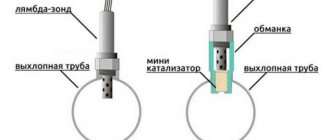
Some engines are equipped with a feedback injection system (oxygen sensor) and a neutralizer in the exhaust system.
This system does not require adjustment or maintenance (if exhaust gas toxicity standards are exceeded, failed components are replaced).
The oxygen sensor and converter are not installed on the other part of the engines.
In this case, the toxicity of exhaust gases is regulated by a CO potentiometer using a gas analyzer.
INJECTION CONTROLLER
It is a special-purpose mini-computer.
It contains three types of memory - random access memory (RAM), programmable read-only memory (PROM) and electrically programmable memory (EPROM)
RAM is used by the computer to store current information about engine operation and process it.
Codes of any faults that occur are also recorded in RAM. This memory is volatile, meaning that when the power is turned off, its contents are erased.
The PROM contains the actual computer program (algorithm) and calibration data (settings).
Thus, the PROM determines the most important parameters of engine operation: the nature of the change in torque and power, fuel consumption, etc. The PROM is non-volatile, i.e. its contents do not change when the power is turned off.
The EPROM is installed in a connector on the controller board and can be replaced (if the controller fails, a working EPROM can be replaced with a new controller).
The immobilizer codes are recorded in the EEPROM when the keys are “learned”. This memory is also non-volatile.
INJECTION SENSORS
They provide the controller with information about the engine operating parameters (except for the vehicle speed sensor), on the basis of which it calculates the torque, duration and order of opening of the injectors, the torque and order of spark formation.
If individual sensors fail, the controller switches to bypass operating algorithms; in this case, some engine parameters may deteriorate (power, throttle response, efficiency), but driving with such malfunctions is possible.
The only exception is the crankshaft position sensor; if it is faulty, the engine cannot run.
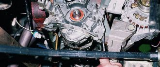
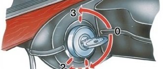
CRANKSHAFT POSITION SENSOR
Installed on the oil pump cover. It provides the controller with information about the angular position of the crankshaft and the moment the pistons pass the 1st and 4th cylinders TDC.
The sensor is of the inductive type and reacts to the passage of the teeth of the drive disk on the generator drive pulley near its core.
The teeth are located on the disk at 6° intervals. To synchronize with TDC, two teeth out of 60 are cut off, forming a cavity.
When a depression passes by the sensor, a so-called synchronization reference pulse is generated in it.
The installation gap between the core and the teeth should be within 1 ± 0.2 mm.
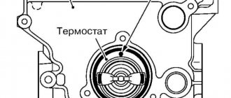
COOLANT TEMPERATURE SENSOR
Screwed into the exhaust pipe on the cylinder head.
It is a thermistor that changes its resistance depending on temperature:
The controller supplies the sensor with a stabilized voltage of +5 V through a resistor and, based on the voltage drop, calculates the engine temperature, adjusting the mixture composition.
THROTTLE POSITION SENSOR (TPS)
Installed on the throttle valve axis and is a potentiometer.
A stabilized voltage of +5 V is supplied to one end of its winding, and the other is connected to ground.
The signal for the controller is removed from the third output of the potentiometer (slider).
To check the sensor, turn on the ignition and measure the voltage between ground and the slider terminal (do not disconnect the connector - the wires can be pierced with thin needles connected to the voltmeter terminals) - it should be no more than 0.7 V.
Turning the plastic sector by hand, fully open the throttle valve and measure the voltage again - it should be more than 4 V.
Turn off the ignition, disconnect the connector, connect an ohmmeter between the slider terminal and any of the two remaining ones.
Slowly turn the sector by hand, following the arrow readings.
There should be no jumps throughout the entire working range. Otherwise, replace the sensor. If the TPS fails, its functions are taken over by the mass air flow sensor. In this case, the idle speed does not fall below 1500 min-1.
MASS AIRFLOW SENSOR
Located between the air filter and the intake hose.
It consists of two sensors (working and control) and a heating resistor.
The passing air cools one of the sensors, and the electronic module converts the temperature difference between the sensors into an output signal for the controller.
In different versions of injection systems, two types of sensors are used - with a frequency or amplitude output signal.
In the first case, the frequency changes depending on the air flow; in the second case, the voltage changes. If the mass air flow sensor fails, its functions are taken over by the TPS.
KNOCK SENSOR
The single-contact knock sensor is screwed into the top of the cylinder block, the two-contact sensor is mounted on a stud.
The operation of the sensor is based on the piezo effect: when a piezoelectric plate is compressed, a potential difference occurs at its ends.
When detonation occurs, voltage pulses are generated in the sensor, according to which the controller regulates the ignition timing.
OXYGEN SENSOR (LAMBDA PROBE)
Installed in the exhaust pipe of the exhaust gas system.
The oxygen contained in the exhaust gases creates a potential difference at the sensor output, varying from approximately 0.1 V (a lot of oxygen - a lean mixture) to 0.9 V (a little oxygen - a rich mixture).
Based on a signal from the oxygen sensor, the controller adjusts the fuel supply to the injectors so that the composition of the exhaust gases is optimal for the efficient operation of the converter (oxygen sensor voltage is about 0.5 V).
For normal operation, the oxygen sensor must have a temperature of at least 360°C, so for quick warm-up after starting the engine, a heating element is built into it.
The controller constantly supplies a stabilized reference voltage of 0.45 ± 0.10 V to the oxygen sensor circuit.
Until the sensor warms up, the reference voltage remains unchanged. In this case, the controller controls the injection system without taking into account the voltage at the sensor.
As soon as the sensor warms up, it begins to change the reference voltage. Then the controller turns off the heating of the sensor and begins to take into account the signal from the oxygen sensor.
CO POTENTIOMETER
It is installed on the front panel (next to the left shock absorber strut cup) and is a variable resistor.
The CO potentiometer is used to adjust the CO level in the exhaust gases of engines not equipped with a catalytic converter.
VEHICLE SPEED SENSOR
Installed in the gearbox on the speedometer drive.
Its operating principle is based on the Hall effect.
The sensor outputs rectangular voltage pulses to the controller (lower level - no more than 1V, upper level - no less than 5V) with a frequency proportional to the speed of rotation of the drive wheels. 6 sensor pulses correspond to 1 m of vehicle travel.
The controller determines the vehicle speed based on the pulse frequency.
IGNITION SYSTEM
Consists of an ignition module, high-voltage wires and spark plugs. During operation, it does not require maintenance or adjustment.
The ignition timing is calculated by the controller depending on the crankshaft speed, engine load (air mass flow and throttle position), coolant temperature and the presence of detonation.
IGNITION MODULE
Includes two control electronic units and two high-voltage transformers (ignition coils).
Spark plug wires are connected to the terminals of the high-voltage windings: to one winding - the 1st and 4th cylinders, to the other - the 2nd and 3rd.
Thus, a spark simultaneously jumps in two cylinders (1-4 or 2-3) - in one during the compression stroke (working spark), in the other during exhaust (idle).
The ignition module is non-separable; if it fails, it is replaced.
SPARK PLUG
A17DVRM or their analogues, with an interference suppression resistor with a resistance of 4-10 kOhm and a copper core.
The gap between the electrodes is 1.0-1.1 mm. The hexagon size is 21 mm.
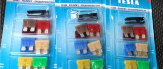
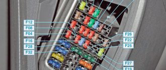
INJECTION FUSES AND RELAYS
Three fuses (15 A each) and three injection system relays (main, electric fuel pump and electric cooling fan) are combined into a block located under the magazine shelf of the instrument panel.
In addition to the fuses, there is a fuse-link at the end of the red wire connected to the “+” terminal of the battery, made in the form of a piece of black wire with a cross-section of 1 mm2 (the cross-section of the main wire is 6 mm2).
The power contacts of the main relay close when the ignition is turned on.
After this, the “plus” is supplied to the relay windings of the electric fuel pump and the electric fan of the cooling system (the relay is turned on at the controller’s command), the injectors (their activation is also at the controller’s command), and the injection system sensors.
Power is supplied to the electric fan relay contacts through a fuse in the mounting block.
INJECTION SYSTEM OPERATION
The composition of the mixture is regulated by the duration of the control pulse supplied to the injectors (the longer the pulse, the greater the fuel supply).
Fuel can be supplied synchronously (depending on the position of the crankshaft) and “asynchronously” (regardless of the position of the crankshaft).
The last mode is used when starting the engine. If, when cranking the engine with the starter, the throttle valve is open more than 75%, the controller perceives the situation as a cylinder purging mode (this is done if there is a suspicion that the spark plugs are filled with gasoline) and does not issue pulses to the injectors, cutting off the fuel supply.
If during purging the engine starts running and its speed reaches 400 min-1, the controller will turn on the fuel supply.
When braking the engine, the controller leans the mixture to reduce the toxicity of exhaust gases, and in some modes it completely turns off the fuel supply.
The fuel supply is also switched off when the ignition is turned off, which prevents self-ignition of the mixture in the engine cylinders.
When the supply voltage drops, the controller increases the time of energy accumulation in the ignition coils (to reliably ignite the combustible mixture) and the duration of the injection pulse (to compensate for the increase in the injector opening time).
As the supply voltage increases, the time of energy accumulation in the ignition coils and the duration of the pulse supplied to the injectors decrease.
The controller controls the activation of the electric cooling fan (via a relay) depending on the engine temperature, engine speed and air conditioning operation (if installed).
The electric fan turns on if the coolant temperature exceeds 104°C or the air conditioning is turned on.
The electric fan turns off when the coolant temperature drops below 101°C, the air conditioning is turned off, or the engine stops (with a delay of several seconds).
CHECK ENGINE LAMP
Installed in the instrument cluster, it informs the driver about malfunctions in the engine control system.
On some cars (with a “January-4.1” controller, GM), it also generates fault codes when the ignition is turned on if the corresponding contacts of the diagnostic connector located under the instrument panel are closed.
On the currently produced “January” and Bosch controllers, self-diagnosis is not provided, and the connector is used to connect a diagnostic device of the DST-2 type.
If the system is working properly, then when the ignition is turned on, the “CHECK ENGINE” lamp lights up, but goes out immediately after the engine starts.
If the lamp lights up while the engine is running, there are malfunctions in the engine management system, the conditional codes of which the controller records in memory (RAM).
Even if the light then goes out, these codes remain in memory and can be read using a scan tool or self-test mode (if equipped).
To erase codes from the controller’s memory, you must disconnect the battery for at least 10 seconds.
However, the failure of some components of the injection system (fuel pump and its circuits, ignition module, spark plugs) is not detected by the controller and, accordingly, the “CHECK ENGINE” lamp does not light up.
When servicing or repairing the engine control system, always turn off the ignition.
When carrying out welding work, disconnect the “-” terminal of the battery and the controller from the wiring harness.
The controller contains electronic components that can be damaged by static electricity, so do not touch its terminals with your hands.
When drying the car in a drying chamber (after painting), remove the controller.
With the engine running, do not disconnect or adjust electrical connectors.
It is forbidden to check the operation of the ignition system “for spark”.
Do not start the engine if the terminals at the battery and ground terminals on the engine and body are loose or dirty.