Car owners are well aware that the VAZ 21214, 21213 (Niva) fuse box is a critical detail that requires detailed study. Knowledge of the electrical circuit allows you to avoid many problems and carry out timely diagnosis of breakdowns. Since the family has existed for many decades, it has managed to go through a number of radical changes - the transition from carburetor to injection engines, for example. This did not entail a radical change in the location and content of the mounting blocks, of which there are two in the cabin and one under the hood.
Fuse box VAZ Niva old and new model
The main difference between the schemes of old and new Niva lies in the method of connecting the additional mounting block, which is located below. If in older models only two fuses are used for this purpose, then in the updated ones there are already four.
In general terms, the difference between the two blocks looks like this:
| New additional block | Old additional block | ||||
| Fuse no. | Current (amps) | What is he responsible for? | Fuse no. | Current (amps) | What is he responsible for? |
| 11 | 8 | Turn signal lamps, relay-breaker for turn signals and emergency lights | 11 | 8 | Reserve |
| 12 | 8 | Daytime running light relay, Daytime running light bulbs | 12 | 8 | Reserve |
| 13 | 8 | Rear fog lights and their relay | 13 | 8 | Fog lights and their relays |
| 14 | 16 | Cigarette lighter | 14 | 16 | Cigarette lighter |
| 15 | 16 | Reserve | 15 | 16 | Reserve |
| 16 | 8 | Reserve | 16 | 8 | Reserve |
Designations of fuses and their purpose
Description of the upper section:
- Rear wiper motor, fluid supply to the front window, heater fan motor.
- Turn signals, reverse indicator, switches under the steering wheel, instrument panel and indicator lights.
- High beam (left headlight), indicator on the dashboard for turning on the high beam.
- High beam (right headlight).
- Low beam (left headlight).
- Low beam (right headlight).
- Dimensions (left side), license plate lighting, indicators on the instrument panel for turning on the dimensions.
- Dimensions (right side), instrument panel lighting.
- Hazard signal relay and power button, heated rear window.
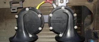
- Brake lights, interior lighting, horn.
All fuses except the first have a rated current of 8A (PR1 - 16A). The bottom row is responsible for the following:
- Storage of 8A inserts
- Similar to the previous one.
- Rear fog lights.
- Cigarette lighter.
- Storage of 16A insert.
- Same for 8A.
The next power supply is responsible for the operation of the engine. The fuse diagram for Niva 21213 assumes 5 positions, and VAZ 21214 with an installed ABS system - 7 (positions 5-7 are responsible for it). The circuit without ABS looks like this:
- Start the electric fan motor on the right (30A).
- A similar position for the left side.
- Injection system control, injection nozzles, ignition coil, fan relay (15A).
- System for reducing the toxic component of gases, sensor of air supplied to the internal combustion engine (15A).
- Connector for diagnosing the operation of the injection system.
VAZ Niva fuse diagram for injector
The Niva with fuel injection has today almost completely replaced the carburetor models of the family. With the transition to a new injection system, the manufacturer tried to minimize the inconvenience for the car owner and not radically change the location of the mounting blocks, as well as their filling with protective elements. Traditionally, there are two of them in the cabin. Another one, in the back, is responsible for controlling the engine.
Fuse box VAZ 21214 Niva with description
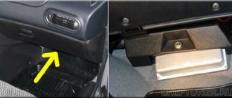
In the interior of the VAZ 21214 Niva with fuel injection there are two fuse blocks. One of them is located in the traditional place - to the left of the driver's hand and the dashboard. But the second one is located below, near the central tunnel, on the passenger side. In the updated models, it was in this block that the fuses responsible for various types of headlights were placed.
Both blocks are connected to each other. The total number of fuses in the upper one is ten, while at the bottom there are six, including reserve ones.
| Fuse no. | Current (amps) | Electric circuit |
| F1 | 16 | Heater fan, rear window defroster, rear wiper and washer system, windshield washer pump |
| F2 | 8 | Steering column switch, windshield wipers, hazard warning lights, breaker relay (in turn signal mode), reverse light, instrument cluster (coolant temperature gauge, fuel level gauge, tachometer, indicator lamps: turn signals, differential lock, parking brake, emergency condition of the working brake system, insufficient oil pressure, fuel reserve, battery charge) |
| F3 | 8 | Left high beam, high beam warning lamp |
| F4 | 8 | Right high beam |
| F5 | 8 | Left low beam |
| F6 | 8 | Right low beam |
| F7 | 8 | Side light lamps in the left front and left rear lights, license plate lights, side light indicator lamp |
| F8 | 8 | Side light lamps in the right front and right rear lamps, backlight lamps for the instrument cluster, cigarette lighter, switches, heating and ventilation control unit |
| F9 | 8 | Hazard switch, breaker relay (in hazard mode), heated tailgate glass relay contacts |
| F10 | 8 | Sound signal, interior lamps, brake lamps in the rear lights |
| F11/F12 | 8 | Reserve |
| F13 | 8 | Fog light relay contacts in rear lights |
| F14 | 16 | Cigarette lighter |
| F15/F16 | 16/8 | Reserve |
In the lower additional mounting block of the VAZ Niva you can find the following electrical protection elements:
| Fuse no. | Current (amps) | What is he responsible for? |
| F11 | 8 | Turn signal lamps and relay-breaker for turn signals and hazard warning lights (in hazard warning mode) |
| F12 | 8 | Daytime running light relay, daytime running light bulbs |
| F13 | 8 | Rear Fog Lamps and Relays |
| F14 | 16 | Cigarette lighter |
| F15 | 16 | Reserve |
| F16 | 8 | Reserve |
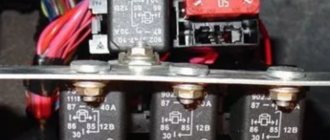
In addition to the two blocks described, in this car you can also find a fuse block responsible for the power plant control system. It is located under the instrument panel on the left side of the body. The reference point is the diagnostic block. In total, 4 elements were placed here:
| Fuse no. | Current (amps) | Responsible part |
| F1 | 30 | Right electric fan relay contacts |
| F2 | 30 | Left electric fan relay contacts |
| F3 | 15 | Relay windings of the right and left electric fans, controller, injectors, ignition coil |
| F4 | 15 | Heating elements for control and diagnostic oxygen sensors, phase sensor, mass air flow sensor, canister purge valve |
Fuse diagram for VAZ 21213 Niva
There is no noticeable difference in the circuits with the injector compared to the VAZ 21214.
VAZ 2131 Niva fuse diagram
Like the VAZ 21214, model 2131 is equipped with two mounting blocks for fuses responsible for most electrical circuits. One additional unit is also equipped with elements designed to protect the motor control system circuits.
Replacing fuses
Before replacing an element, it is necessary to eliminate the cause of its failure. Do not use fuses of a different rating. The calculated current strength for each circuit can be found in the assignment table located above in the article.
The protective device may fail due to long periods of use, so if any consumer stops working, the first thing to check is its fuse.
They are held in their nests by sliding contacts. In order to remove the element, simply pull it out of the socket. To make this more convenient, modern mounting blocks are equipped with plastic tweezers.
A faulty fuse can be determined by visual inspection or using an ohmmeter. Since the housings are made of transparent plastic, the integrity of the conductor is easy to determine with the naked eye. In addition, conductor burnout is accompanied by an increase in temperature. Traces of heat exposure remain on the plastic case. Having selected an element suitable for its nominal value, it is inserted into the socket in place of the failed one.
In no case should you use bugs instead of a fuse, as they may not burn out when the current increases, which will lead to overheating and fire of the wiring.
If a fuse burns out on the road, you can replace it with an identical one that protects the circuit of the consumer that is not currently in use.
More information about Chevrolet Niva electronics can be found here.
Chevrolet Niva is a five-door compact SUV (SUV class) with permanent all-wheel drive. Produced from 2002 to the present. In 1998, AvtoVAZ presented at the Moscow Motor Show a concept car that was supposed to replace the familiar Niva. The concept received the VAZ-2123 index. In 2006, the rights to the Niva brand were transferred to General Motors. Chevrolet Niva has permanent all-wheel drive - unlike its main “rival” - Renault Duster. The main disadvantages of the Chevrolet Niva are its weak 80-horsepower engine, which provides very modest dynamics, the absence of ABS and a high noise level in the cabin. In 2009, the car was restyled. I would like to add that the restyled version of the car has no mechanical changes, only the exterior and interior have been updated.
- Page navigation
- Mounting block – restyl
- Mounting block – dorestayl
- Fuses and relays KSUD
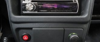
Fuse box - located to the left of the steering column under the instrument panel. To access the block, you need to unscrew two screws and press down the decorative cover (held in rubber bushings). This car is equipped with two types of mounting block, respectively the doreystyle and restyle versions (see information below).
Fuse diagram for carburetor VAZ Niva
The only difference between Niva mounting blocks with injection and carburetor systems is related to the block. It is located under the hood of the car in a compartment specially designated for this purpose. His diagram looks like this:
Location of fuses Niva 21213
This scheme is relevant for all models of the family produced from 1997 to 1999.
| Number | Purpose |
| 1 | Ignition switch |
| 2 | Main relay |
| 3 | Used coil |
| 4 | Valve |
| 5 | Carburetor switch |
| 6 | Reserve |
Fuse diagram for VAZ 2121 Niva
In the model with injection supply, the fuels are located in the same way as in other models of the family of this type.
Engine control system fuses
| F1 (30A) | Right electric fan relay contacts |
| F2 (30A) | Left electric fan relay contacts |
| F3 (15A) | Relay windings of the right and left electric fans, controller, injectors, ignition coil |
| F4 (15A) | Heating elements for control and diagnostic oxygen concentration sensors, phase sensor, mass air flow sensor, canister purge valve |
Also interesting: Construction and repair of the VAZ 2121 Niva transfer case
| №1 | Ignition relay |
| №2 | Main relay |
| №3 | Right cooling fan relay |
| №4 | Left cooling fan relay |
| №5 | Fuel pump relay (fuel) |
| №6 | Fuel pump fuse F5, 15A |
On some vehicle versions, a starter relay may be located under the additional unit next to the ignition relay.
| F1 (30A) | Right electric fan relay contacts |
| F2 (30A) | Left electric fan relay contacts |
| F3 (15A) | Relay windings of the right and left electric fans, controller, injectors, ignition coil |
| F4 (15A) | Heating elements for control and diagnostic oxygen concentration sensors, phase sensor, mass air flow sensor, canister purge valve |
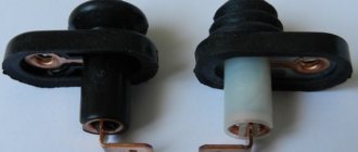
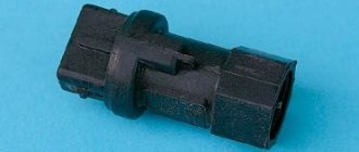
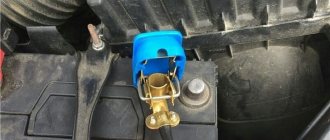
Starter relay VAZ 2131 injector where is it located
Starting with modification 21213, the Niva is equipped with a starter interlock relay, which helps to avoid burnout of the contact group (contact “50”) of the ignition switch, which often happened in the past.
(Not to be confused with the ignition relay and main relay, which are located in the passenger compartment (see here))
To replace the starter interlock relay, open the hood.
It is installed on the brake fluid reservoir mounting stud.
Using a 10mm spanner, unscrew the relay mounting nut.
Disconnect the wiring harness connector from the relay.
Install the new relay in reverse order.
Where is Niva Chevrolet starter relay
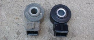
Let's figure out what a relay is, where to find it, what its role is and what to do when it fails.
A relay is a device that is constantly powered by electric current from a battery. It consists of a gear with teeth that engages the flywheel ring when the relay begins to operate. As a result, the engine crankshaft rotates and the car starts. During operation, the relay connects the flywheel and bendix gears. The starter will run empty if the relay does not advance the gear.
When the engine is started, during the ignition operation, power is supplied to all the windings that are located in the starter. These windings come in two types: retracting and holding. The starter is connected to the retractor winding, and the entire housing control circuit begins to work thanks to the holding winding. When current flows to the terminals, magnetic induction occurs, which creates a magnetic field. Thus, the armature presses on the return spring, and the bendix rotates. When the engine starts running, the power is turned off and the armature returns to its original position as the spring returns it. The contacts are disconnected.