Any car will last you for the rest of your life if you drive hard enough
Injection power units on rear-wheel drive classics, a prominent example of which is the VAZ 2107-20, have had a serious impact on the domestic passenger car fleet. But not all car owners initially appreciated the advantages of the injection system in comparison with a traditional carburetor, fearing more difficulties in the operation of electronic components. Is this really so, we will try to figure it out within the framework of this article.
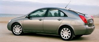
Representative of the rear-wheel drive VAZ family, which received an injection system
What's new
The main innovation was the replacement of the mechanical functions of the ignition system and preparation of the air-fuel mixture with electronic devices, which are more accurate and efficient. The wiring diagrams of the VAZ 2112 and the Samara family also underwent a similar modernization. Accordingly, the wiring of the VAZ 2107 to the injector received differences from the carburetor version.
Under the hood of the VAZ 2107-20, the absence of a carburetor and distributor is immediately striking
ECM functions
The electronic engine control system (abbr. ECM) took on the following operating parameters of the power unit:
- Controlling the amount of air and gasoline entering the car engine cylinders,
- crankshaft speed
- Spark plug control;
- Adjustment of ignition timing in all operating modes;
- Turning the electric fuel pump on and off,
- Control of the electric fan of the engine cooling system.
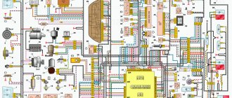
The photo below shows a VAZ 2107 wiring diagram for an injector with an M1.5.4N ECM and a January-5.1.3 controller
Injection system VAZ 2107
Electrical diagram
The classic 2107 wiring on cars with an injection system has also undergone changes. In particular, under-hood elements equipped with connectors for sensors and electronic devices have appeared.
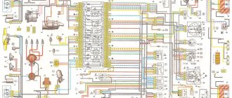
Electrical diagram of VAZ 2107 with carburetor
For reference: The developers of Moskvich 2141 followed a similar path. True, they had a more global problem - the lack of their own engine.
Explanation for the electrical diagram of the carburetor VAZ 2107
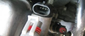
For reference: The photo below shows the electrical wiring of a VAZ 2107 to an injector with catalog numbers. The differences from carburetor kits are in the engine compartment harnesses.
When converting the engine to an injection system, you should also purchase new wiring
Differences in work
Advantages
So, what are the benefits received by the car owner whose car has injection installed:
- There is less chance of stalling when starting from a standstill - the electronics react more flexibly to the operation of the gas pedal, allowing you to move off more confidently from idle;
The engine compartment wiring harness of the VAZ 2107-20 has different connectors
- Easy engine starting - there is no need to manually operate the choke knob;
- Reduced warm-up time for a cold engine - the electronic system optimizes the minimum stable speed. You can start moving after starting, without fear of jerks and dips typical of a carburetor;
- Reduce routine maintenance of electrical equipment . In particular, there is no need to constantly adjust the gap in the breaker contacts;
For reference: Other domestic car factories also modernized electrical equipment, in particular the ignition system - see the publication on the UAZ 31514 wiring diagram.
- Reduced adjustment work on the carburetor - electronics can reduce fuel consumption and make engine operation more environmentally friendly.
In the video you can see the stable start of the VAZ 2107 injection engine.
Flaws
The injection system also has some flaws, in particular:
- Without a diagnostic tool, it is quite difficult to identify a malfunction in the engine management system;
- Standard wiring 2107 does not allow troubleshooting using a warning lamp;
- The factory instructions most often instruct you to contact a service center for diagnostics. However, the price of such a service is not always justified for the car owner.
In the photo - diagnostics of the oxygen sensor of the VAZ 2107
Method one - forced mechanical cooling
Perhaps you can call it that. Remember the first VAZ 2101-2107 cars, which did not use electric fans. In them, the radiator was blown through an impeller screwed to the pump rotor. The exact same fan can be installed on a VAZ 2107 injector. The design of the cooling system is not much different.
But we must immediately mention some of the features of this design. The fact is that even in winter the radiator will be blown by air flow. This reduces the engine temperature, so the cabin can be quite cool. It’s good in the summer - the engine is always cooled, the fan is constantly running, the antifreeze does not boil.
But make two more small improvements and summer operation will be just a fairy tale:
- Place a plastic diffuser that will direct the air beam into the radiator honeycombs.
- The upper part of the radiator needs to be installed a little closer to the impeller blades. Fasteners should be made using small strips of hard metal. Try to ensure that the distance from the surface of the radiator to the impeller is in the range of 2-4 cm.
These are the little tricks that will help you improve the cooling of the VAZ 2107 engine. The price of the issue is literally meager - no more than 80 rubles (that’s how much the impeller costs).
Electrical diagram VAZ-2107 carburetor
Electrical diagram of VAZ 2107, 21074 produced in 1988-2001 with generator 37.3701
- block headlights
- side direction indicators
- accumulator battery
- starter relay
- carburetor electro-pneumatic valve
- carburetor microswitch
- generator 37.3701
- gearmotors for headlight cleaners *
- Fan motor switch sensor
- engine cooling fan motor
- sound signals
- distributor
- spark plug
- starter
- coolant temperature gauge sensor
- engine compartment lamp
- low oil pressure warning sensor
- low brake fluid level indicator sensor
- windshield wiper motor
- carburetor electro-pneumatic valve control unit
- ignition coil
- headlight washer pump motor *
- windshield washer pump motor
- mounting block
- windshield wiper relay
- hazard warning and direction indicator relay
- brake light switch
- reverse light switch
- ignition relay
- ignition switch
- three lever switch
- hazard switch
- socket for portable lamp**
- heater fan switch
- additional resistor for the electric motor of the heater (stove)
- rear window heating indicator lamp
- low brake fluid level warning lamp
- signaling unit
- heater fan electric motor
- glove compartment lamp
- light switches on the front door pillars
- switches for warning lights of open front doors ***
- front door open warning lights ***
- connection block
- cigarette lighter
- watch
- instrument light switch
- diode for checking the serviceability of the low brake fluid level indicator lamp
- fuel level indicator
- fuel reserve indicator lamp
- speedometer
- turn signal indicator lamp
- carburetor choke indicator lamp
- battery charge indicator lamp
- carburetor choke warning switch
- instrument cluster
- econometrician
- light switches on the rear door pillars
- coolant temperature gauge
- tachometer
- parking brake indicator lamp ("handbrake")
- low oil pressure warning lamp
- high beam indicator lamp
- indicator lamp for turning on external lighting
- voltmeter
- parking brake indicator switch ("handbrake")
- outdoor light switch
- rear window heating switch with backlight
- rear fog light switch with on/off indicator *
- fog light circuit fuse
- lampshade ****
- tail lights
- level indicator and fuel reserve sensor
- connectors for connecting to the rear window heating element *
- license plate lights 2107
Wiring diagram VAZ-2107 carburetor - full view:
Integrated power supply diagrams for VAZ 2104
All VAZ 2104 systems that consume electricity are switched over a single-wire line. The sources of electricity are the battery and the generator. The positive contact of these sources is connected to electrical devices, and the negative contact goes to the body (ground).
Electrical equipment of the VAZ 2104 is divided into three types:
- working equipment (battery, generator, ignition, starter);
- auxiliary operating equipment;
- light and sound alarm.
When the engine is turned off, all electrical equipment, including the starter, is powered by the battery. After the engine is started by the starter, the generator becomes the source of electricity. At the same time, it restores battery charge. The ignition system creates a spark discharge to ignite the fuel-air mixture entering the engine. The functions of the light and sound alarm include external lighting, interior lighting, turning on the headlights, and sounding a sound signal. Electrical circuits are switched through the ignition switch, which consists of an electrical contact unit and a mechanical anti-theft device.
The VAZ 2104 uses a 6ST-55P battery or similar. Synchronous generator 37.3701 (or G-222) is used as an alternating current source. This is a three-phase generator with electromagnetic excitation and a built-in rectifier unit based on silicon diodes. The voltage taken from these diodes powers the rotor winding and is supplied to the battery charge indicator lamp. On cars with a 2105–3701010 generator, this lamp is not used, and the battery charge level is monitored by a voltmeter. The generator is mounted on brackets in the right (in the direction of travel) front part of the engine compartment. The generator rotor is driven by a crankshaft pulley. The starter 35.3708 is attached to the clutch housing on the right side of the engine, protected by a heat-insulating shield from the exhaust system pipe and activated by an electromagnetic remote control relay.
The VAZ 2104 uses a contact ignition system, and in cars manufactured after 1987, a contactless ignition system. The contact system contains the following elements:
- a distributor-breaker designed to open the ignition coil circuit with a low voltage current and distribute high voltage pulses across the spark plugs;
- ignition coil, the main function of which is to convert low voltage current to high voltage current;
- spark plug;
- high voltage wires;
- ignition switch.
The contactless system consists of:
- a distribution sensor that supplies low voltage control pulses to the switch and distributes high voltage pulses across the spark plugs;
- a switch designed to interrupt the current in the low voltage circuit of the ignition coil in accordance with the signals of the distribution sensor;
- ignition coils;
- spark plugs;
- high voltage wires.
Current is constantly supplied to electrical circuits:
- sound signals;
- brake lights;
- cigarette lighter;
- interior lighting;
- portable lamp sockets;
- emergency light signaling.
To switch and protect electrical appliances from voltage surges, in a special niche in the engine compartment there is a mounting block with fuses and relays, the purpose of which is schematically indicated on the cover of the block. The standard unit can be removed, the board can be replaced, or its conductive paths can be restored.
On the dashboard of the VAZ 2104 there are power keys:
- external lighting fixtures;
- fog lights;
- heated rear window;
- interior heating.
The light alarm button is located on the protective cover of the steering column shaft, and under the column there are switches for low and high beams, turn signals, wipers and windshield washer.
Electrical diagram of VAZ 21043 and 21041i (injector)
Models VAZ 21043 and 21041i (sometimes incorrectly designated as 21047) have identical power supply circuits. All electrical equipment of these cars is similar to that of the VAZ 2107.
The export version of the VAZ 2104 and VAZ 21043 additionally includes a wiper and heated rear window. Since 1994, this scheme has become the standard for all produced fours. After the appearance of injection models, the scheme was slightly changed. This was also due to the appearance of a five-speed gearbox, electrical equipment and interior from the VAZ 2107, as well as electronic components that control engine operation.
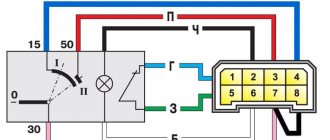
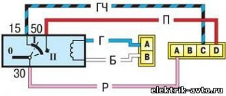
Mounting block connection diagram
P1 — relay for turning on the heated rear window; P2 - relay for turning on the headlight cleaners and washer; P3 - relay for turning on sound signals; P4 - relay for switching on the electric motor of the engine cooling system fan; P5 - headlight high beam relay; P6 - low beam headlight relay; A - the order of conditional numbering of plugs in the mounting block blocks. The outer number with the letter “Ш” in the plug designation is the block number, and the inner number is the conventional number of the plug.
If the cooling fan does not work
To drive the fan, a DC electric motor with excitation from permanent magnets ME-272 or similar is installed. Technical data of the electric fan and fan switch sensor:
- Rated rotation speed of the electric motor shaft with impeller, 2500 – 2800 rpm.
- Electric motor current consumption, 14 A
- Sensor contact closure temperature, 82±2 degrees.
- Sensor contact opening temperature, 87±2 degrees.
The cooling system fan may not turn on due to:
- electric drive malfunctions;
- blown fuse;
- faulty thermostat;
- a failed thermal sensor for turning on the cooler;
- faulty VO relay;
- broken electrical wiring;
- faulty expansion tank plug.
To check the VAZ fan electric motor itself, we apply 12 V voltage from the battery to its terminals - a working motor will work. If the problem is with the fan, you can try to repair it. The problem is usually the brushes or bearings. But it happens that the electric motor fails due to a short circuit or break in the windings. In such cases, it is better to replace the entire drive.
The BO fuse is located in the mounting block of the car's engine compartment and is designated F7 (20 A). The test is carried out using a car tester turned on in probe mode.
- In a car with a carburetor engine,
you need to check the sensor - turn on the ignition and short-circuit the two wires going to the sensor. The fan should turn on. If this does not happen, the problem is definitely not with the sensor. - For injection cars,
it is necessary to warm up the engine to operating temperature and disconnect the sensor connector, disconnecting it from the vehicle’s on-board network. In this case, the controller must start the fan in emergency mode. The electronic unit perceives this as a failure in the cooling system and forces the fan drive to operate in constant mode. If the drive starts, the sensor is faulty.
Schemes of individual blocks of the seven
Power supply system
Power plant starting system
1 - starter; 2 - relay; 3 — ignition switch; 4 - battery
Ignition system
1 - generator; 2 — ignition switch; 3 - distributor; 4 - breaker; 5 — candles; 6 - coil; 7 - battery
Contactless ignition system
External and internal lighting
Windshield wipers and washers
1 — electric motors of the windshield wiper; 2 — washer motor; 3 — mounting block; 4 — ignition switch; 5 - washer switch
Cooling Fan
1 — fan electric motor; 2 - sensor; 3 — mounting block; 4 - ignition relay; 5 - ignition switch.
Wires for connecting electrical appliances
| Connection type | Section, mm 2 | Insulation color |
| Negative terminal of the battery - vehicle ground (body, engine) | 16 | Black |
| Starter positive terminal - battery | 16 | Red |
| Positive contact of the generator - plus battery | 6 | Black |
| Generator - black connector | 6 | Black |
| Terminal on the generator “30” – white MB block | 4 | Pink |
| Starter connector “50” – starter relay | 4 | Red |
| Starter Start Relay - Black Connector | 4 | Brown |
| Ignition switch relay - black connector | 4 | Blue |
| Ignition switch output “50” – blue connector | 4 | Red |
| Ignition switch connector “30” – green connector | 4 | Pink |
| Right headlight plug - ground | 2,5 | Black |
| Left headlight plug - blue connector | 2,5 | Green, gray |
| Generator output “15” – yellow connector | 2,5 | Orange |
| Right headlight connector - ground | 2,5 | Black |
| Left headlight connector - white connector | 2,5 | Green |
| Radiator fan - ground | 2,5 | Black |
| Radiator Fan - Red Connector | 2,5 | Blue |
| Ignition switch output “30/1” – ignition switch relay | 2,5 | Brown |
| Ignition switch contact “15” – single-pin connector | 2,5 | Blue |
| Right headlight - black connector | 2,5 | Grey |
| Ignition switch connector “INT” – black connector | 2,5 | Black |
| Six-pin block of the steering column switch - “ground” | 2,5 | Black |
| Two-pin block of the steering column switch - glove box illumination lamp | 1,5 | Black |
| Glove compartment light - cigarette lighter | 1,5 | Black |
| Cigarette lighter - blue block connector | 1,5 | Blue, red |
| Rear window defroster - white connector | 1,5 | Grey |
Diagram of side harnesses VAZ 2114 injector
- — block of the side door wiring harness to the instrument panel harness;
- — block of the side door wiring harness to the seat heating harness;
- — electric lock of the right rear door;
- — electric lock of the left rear door;
- — harness pads to the rear right loudspeaker;
- — harness pads to the rear left loudspeaker;
- — door lock control unit;
- — blocks of the side door wiring harness to the additional left harness;
- — blocks of the side door wiring harness to the additional left harness;
- — terminals of the side door wiring harness to the car radio;
- — side door wiring harness block to the additional right harness;
- — additional right wiring harness block to the side door harness;
- — electric window lifter motor;
- — harness pads to the front right loudspeaker;
- — electric lock of the right front door;
- - power window switch;
- — block of the wiring harness of the additional left harness to the side door harness;
- — block of the wiring harness of the additional left harness to the side door harness;
- — driver's door window lifter motor;
- — harness pads to the front left loudspeaker;
- — electric lock of the right front door;
- — driver's door power window switch;
- — power window switch (lock);
A1 - grounding points of the wiring harness.
Car wiring diagram
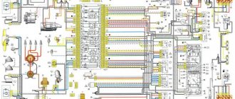
1 – radiator fan drive motor; 2 – relay and fuse block (mounting block); idle speed sensor; 4 – engine control unit; 5 – potentiometer; 6 – set of spark plugs; 7 – ignition control unit; 8 – electronic crankshaft sensor; 9 – electric fuel pump; 10 – tachometer 2107; 11 – lamp for monitoring the health of electronic systems; 12 – ignition system control relay; 13 – speed sensor; 14 – diagnostic connector; 15 – set of injectors; 16 – adsorber solenoid valve; 17, 18, 19 – fuse block protecting the injection system circuits; 21 – electronic fuel pump control relay; 22 – electronic relay for controlling the intake pipe heating system; 23 – intake pipe heating system; 24 – fuse protecting the heater circuit; 25 – electronic oxygen level sensor; 26 – cooling system temperature control sensor; 27 – electronic air damper sensor; 28 – air temperature sensor; 29 – pressure control sensor.
VAZ 21074 engine control system diagram
Wiring diagram of electrical connections of ECM VAZ 21074 - circuit elements. 1 — controller connector; 2 — mass air flow sensor; 3 — coolant temperature sensor; 4 — crankshaft position sensor; 5 — throttle position sensor; 6 — oxygen concentration sensor; 7 — speed sensor; 8 — ignition module; 9 — solenoid valve for purge of the adsorber; 10 — electric fan relay; 11 — electric fuel pump relay; 12 - main relay; 13 - fuse for the power circuit of the electric fuel pump relay: 14 - fuse for the power circuit of the main relay; 15 — fuse-link; 16-fuse protecting the constant power supply circuit of the controller; 17 - diode; 18 — idle speed regulator; 19 — nozzles; X1 - diagnostic block; X2 - connection block to the vehicle electrical system.
Fuse and relay diagram 2107
On newer “sevens” a block with 17 fuses and 6 relays is installed. VAZ 2107 fuses on the “new” unit protect the following electrical circuits and devices:
- Reversing lamps, heater fan, rear window defroster warning lamp and relay, rear wiper motor and rear washer pump.
- Electric motor for front wipers.
- Reserve socket.
- Reserve socket.
- Power supply for heated rear window.
- Clock, cigarette lighter, power socket “carrying”.
- Signal and radiator fan.
- Turn signal lamps in emergency mode.
- “Fog lights” and a relay that regulates the voltage of the on-board network.
- Instrument panel lamps.
- Brake light bulbs.
- Right high beam headlight.
- Left high beam headlight, high beam warning lamp.
- Side lights (rear right, front left), license plate and engine compartment lighting.
- Side lights (rear left, front right), glove compartment and cigarette lighter lamps.
- Low beam (right lamp).
- Low beam (left lamp).
The block relays perform the following functions:
- Heated rear window relay.
- Headlight cleaner and washer relay.
- Signal relay.
- Cooling system electric fan relay.
- High beam relay.
- Low beam relay.
The fuse block of the VAZ 2107 (injector) is no different from the block on the carburetor “seven”. Injection models are simply equipped with an additional relay and fuse box installed in the cabin under the glove compartment. The block includes three relays - the “main” relay, the fuel pump relay and the fan relay.
Mechanical forced cooling of the VAZ 2107 radiator
On older VAZ models, the radiator was cooled using an impeller mounted on the water pump rotor. This solution ensured constant airflow to the radiator when the engine was running. Considering that the design of the VAZ 2107 differs little from its “predecessors”, installing such an impeller will not be difficult.
The advantage of this solution is reliability. Forced mechanical airflow of the radiator ensures that the car does not boil while sitting in a traffic jam on a hot day. But at the same time, the efficiency of blowing at low speeds is reduced in comparison with electric blowing. In winter, another disadvantage of forced cooling appears - a cold engine is additionally blown by a fan, which slightly slows down its warming up. The fact that the fan blows on the radiator on a cold engine does not in any way affect the warm-up speed provided the thermostat is working. The fact is that before the engine warms up, the coolant circulates through a small circuit, bypassing the radiator.
The mechanical drive of the VAZ 2107 cooling fan can be improved
:
- Install a diffuser that directs the air flow through the radiator honeycombs. This will improve cooling efficiency.
- Move the radiator a little back, closer to the impeller. To do this, you can tilt its upper part, using rigid steel strips for fastening. The slats must be calculated so that the distance between the radiator and the impeller is approximately 2040 mm.
This way you can protect your car from overheating.
Modifications of the VAZ-2107 car
VAZ-2107 . Basic version of the sedan, with an 8-valve carburetor VAZ-2103 engine, 1.5 liters.
VAZ-2107-20 . The same VAZ-2107, but with a 1.5-liter VAZ-2104 injection engine that meets the Euro-2 environmental standard.
VAZ-2107-71 . The car for the Chinese market was equipped with a VAZ-21034 engine, with a volume of 1.4 liters and a power of 66 horsepower, specially tuned for A-76 gasoline. The pistons were taken from a VAZ-2108.
VAZ-21070 . Modification of a car with an 8-valve, carburetor VAZ-2103 engine, volume 1.5 liters.
VAZ-21072 . Modification with an 8-valve carburetor VAZ-2105 engine, volume 1.3 liters.
VAZ-21073 . An export modification for the European market, which was equipped with a 1.7-liter injection engine with a capacity of 84 horsepower. The engine of this car had a catalytic converter that satisfied environmental protection requirements.
VAZ-21074 . Modification with an 8-valve, carburetor VAZ-2106 engine, volume 1.6 liters.
VAZ-21074-20 . Modification with a 1.6-liter VAZ-21067-10 injection engine, which complies with the Euro-2 environmental standard
VAZ-21074-30 . Like the previous model, but with a VAZ-21067-20 engine, which meets the Euro-3 environmental standard
VAZ-210740 . Modification produced in 2010, equipped with a VAZ-21067 injection engine with a catalyst. Engine capacity is 1.6 liters, power is 72.7 horsepower.
VAZ-21076 . Export modification with a VAZ-2103 carburetor engine.
VAZ-21077 . Export modification with right-hand drive for the UK market. The car was equipped with a VAZ-2105 carburetor engine with a volume of 1.3 liters.
VAZ-21078 . Another export modification for the UK, but with a 1.6-liter VAZ-2106 carburetor engine
VAZ-121079 . The modification, developed specifically for the needs of the Ministry of Internal Affairs and the KGB, was equipped with a powerful VAZ-413 rotary piston engine with a volume of 1.3 liters and a power of 140 horsepower.
VAZ-2107 ZNG . The car is equipped with an 8-valve, fuel-injected VAZ-21213 engine with a volume of 1.7 liters.
Car modifications
VAZ-2104 . The basic version of the station wagon, with a carburetor engine from the VAZ-2105, 1.3 liters and 64 horsepower. Equipped with a 4-speed gearbox.
VAZ-21041 . A prototype of a station wagon, it was equipped with a carburetor engine from a VAZ-2101, with a volume of 1.2 liters and a power of 62 hp. Just like the base model, it was equipped with a 4-speed manual transmission.
VAZ-21042 . Export version, the steering wheel was located on the right. The car also received a carburetor engine from the VAZ-2103, with a volume of 1.5 liters and a power of 72 hp.
VAZ-21043 . The car was equipped with electrics and interior from a VAZ-2107, some copies had a VAZ-2106 interior. The carburetor engine was borrowed from the VAZ-2103. The gearbox was either 4 or 5 speed.
VAZ-21044 . An export model, equipped with a 1.7-liter VAZ-2107 engine with mono-injection, as well as a 5-speed gearbox.
VAZ-21045 . The export version with a 1.8-liter engine did not enter mass production.
VAZ-21045D . It was produced in small series since 1999, equipped with a VAZ-341 diesel engine with a volume of 1.52 liters and a power of 50 horsepower. The gearbox is 5-speed.
VAZ-21047 . A prototype with an engine starting from a penny. An improved version of the Four, it was equipped with a VAZ-2107 interior and a VAZ-2103 carburetor engine with a volume of 1.5 liters and a power of 72 hp. The gearbox was 5-speed. On export versions, the radiator grille was installed from the VAZ-2107.
VAZ-21048 . Diesel station wagon, with a 1.77-liter VAZ-343 engine. The gearbox is 5-speed.
VAZ-21041i . A car equipped with a VAZ-21067 injection engine. volume 1.6 liters. The gearbox is 5-speed. The electrical equipment and interior are from a VAZ-2107 car, and the front seats are from the Izhevsk hatchback IZH-2126.
VAZ-21041 VF . The interior, electrics and front seats are the same as the previous modification; the radiator grille is also borrowed from the VAZ-2107. It was equipped with a 1.5 liter injection engine from the VAZ-2103 and a 5-speed manual transmission.
The VAZ 2104 with rear-wheel drive and a station wagon body was produced from 1982 to 2012. The model was constantly improved: electrical equipment was changed, a fuel injection system, a five-speed gearbox and semi-sports front seats appeared. The VAZ 21043 modification was supplemented with a system for cleaning and heating the rear door window. The power supply system for individual vehicle components is quite simple.