How to understand that you need to set the ignition
There are several indirect signs that are worth looking at. Of course, if the engine does not start, then turning the ignition on is the first thing that comes to mind, unless of course the spark plugs are wet. Let's look at the main symptoms that indicate the need to install the ignition.
Signs that an ignition installation is required:
- Increased fuel consumption. Of course, this may be a consequence of improper carburetor adjustment, but it also happens. For example, when ignition is delayed, the car’s dynamics decrease; in order to achieve the same acceleration, a larger amount of combustible mixture is required.
Loss of dynamics. With late ignition, the explosion follows the piston, which has already gone down under the influence of the inertia of the flywheel.
Silencer shots. When the explosion occurs afterward, the expansion of the gases takes some time. If the piston has already reached bottom dead center, then the exhaust stroke comes next. This means that part of the fuel explosion will be transferred to the exhaust system, hence the popping noise.
Accurately and on time
Two main parameters that must be checked and adjusted during maintenance are the angles of the closed state of the contacts and the ignition timing. The magnitude of the current in the primary circuit and the sparking voltage in the secondary circuit depend on the UZSK. If this angle is small, interruptions in sparking occur. And it decreases as the contacts wear. This parameter is individual for each engine model (see table).
To install the UZSK, autotesters or homemade devices are used. If they are not there, you can get by by adjusting the gap between the contacts. The latter method is less accurate, since a deviation of the gap from the nominal by only 0.2 mm leads to a decrease in the ignition timing by 6 - 8o, which causes a drop in power by at least 1-2%.
The ignition timing is adjusted after installing the UZSK. The simplest method - using a light bulb or LED - is described in many machine manuals. Experienced motorists can adjust the ignition timing with the engine running by turning the distributor housing when its fastening is released. Service station technicians check the correct installation using a strobe light.
| Contact angle of some motors |
| Engine model | Distributor | UZSK, city | Contact gap, mm |
| VAZ-2101 – 2106 | R-125, R-125D | 55±3 | 0,4±0,03 |
| ZMZ-24 "Volga" | R-119B | 39±3 | 0,4±0,05 |
| UMZ-412 "Moskvich" | R-118, R-147 | 43±4 | 0,4±0,05 |
| MeMZ-968, -966 “Zaporozhets” | R-114, R-114B | 43±4 | 0,4±0,05 |
How to set the ignition on a VAZ 2106 - procedure
First, you will need to install the ignition mark. The crankshaft can be rotated either using a ratchet or using a special wrench using the nut. On the front cover of the engine and on the crankshaft pulley there are ebbs and notches, the combination of which corresponds to different ignition timing:
The first mark in the direction of travel is an advance of the ignition angle by 10 degrees. Angle advance is an adjustment to the fuel burning rate. So, 10 degrees is the mark for 72 gasoline.
Next comes the middle mark - 5 degrees ahead. It is for 80 gasoline.
After the installation of the ignition mark is completed, you must immediately set the required gap in the contacts, naturally, where they exist. To do this, remove the distributor slider and unscrew the breaker fixing screw.
Before setting the gap, it is advisable to clean the contacts with sandpaper (600-800)
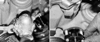
Well, now we go directly to the ignition installation of the VAZ 2106. We unscrew the distributor mount (nut 13), and then pull it out of the housing.
Now you need to insert the distributor into place, taking into account several mandatory points:
- We set the top dead compression stroke mark in the first cylinder; accordingly, at this moment the spark should appear in it. In order to catch this moment, we put the cover on the distributor and mark the place where the armored wire from the spark plug of the first cylinder enters. Now you need to remove the cover and align the outer contact of the slider exactly opposite the mark. That is, at the moment when the piston is at top dead center, a spark is supplied from the central wire of the distributor through the contacts of the runner to the armored line from the first cylinder.
Contact-transistor ignition system
In order to optimize the circuit, the developers added a transistor switch to the design, which is installed in the primary winding. It is controlled using breaker contacts.
The circuit diagram is shown below.
The peculiarity of the system is that the use of an additional device made it possible to reduce the current in the circuit and extend the life of the contact group of the breaker (it began to burn less).
The contact-transistor circuit, thanks to minor changes, has received better characteristics when compared with the classic ignition option. Due to the use of a transistor, a new node was added to the system - a switch.
The advantage of the transistor in this circuit is that even a small current directed to the control (to the base) is enough to control a larger current.
As already noted, the new contact-transistor type system has slight differences from the previous version of the system. Its peculiarity lies in the special characteristics that the standard contact circuit cannot boast of.
The main difference is that the chopper interacts directly with the transistor, rather than with the bobbin. Otherwise, the operation of the contact-transit system is similar.
As soon as the current in the primary winding is interrupted, a high voltage pulse occurs in the second circuit.
If you do not pay attention to the design features and principles of connecting the switch, you can highlight one main advantage - the ability to increase the primary current thanks to the use of a transistor.
At the same time, it is possible to solve a number of problems:
- Increase the gap between the spark plug electrodes;
- Raise secondary voltage;
- Eliminate problems with starting at low temperatures;
- Optimize the spark formation process;
- Increase engine speed and power.
Another feature of the contact-transistor circuit is the need to use a coil with a separate primary and secondary winding.
The considered changes to the circuit made it possible to reduce the load on the contact group of the breaker and reduce the current passing through it. As a result, contacts last longer and system reliability increases.
Despite the considered advantages, one cannot fail to note a number of disadvantages of the contact-transistor system, which are associated with the operation of the breaker.
Thus, a spark is formed in the circuit at the moment when the current in the “bobbin” is interrupted. The current that enters the transistor is of sufficient magnitude to affect the operation of the part.
In addition, a decrease in current at the breaker contact group negatively affects certain system characteristics.
Ignition adjustment of VAZ 2106
Setting the ignition is half the battle, because then it needs to be adjusted. After starting the engine, you need to warm it up, accelerate to 40 km/h in third gear, then turn on fourth and press the gas pedal about halfway, maybe three-quarters, but not to the floor. There are a couple of scenarios for the development of events, each of which requires its own solution.
- Brief detonation that disappears after a couple of seconds. This is normal, this is how it should be. If it passes within 4-5 seconds, then further ignition adjustment is not required.
Long detonation. This indicates that the ignition is too early. In order to do it later, you need to stop, loosen the distributor housing, holding it with your hand, and then turn it one notch on the housing in the “+” direction. Then perform the same operation if the detonation lasts longer than the time indicated above.”
When adjustment is needed
A breaker or distributor on a VAZ 2107 is a device through which high voltage is distributed, supplied to the spark plugs through high-voltage wires. The device is called a chopper because it receives voltage from the coil and, at the moment of compression of the fuel mixture in one of the four cylinders, supplies a voltage pulse to the spark plug of this cylinder. The operating cycle of the classic distributor is 1-3-4-2 cylinders.
Signs of the need to regulate the VAZ 2107 distributor may be as follows:
- The engine cannot be started. The reason may be the lack of clearance between the contacts of the breaker, as well as their contamination, a malfunction of the capacitor, a breakdown of the cover, or even damage to the low-voltage cable.
- At idle speed there is a “shaking” effect of the engine. The reason for this is the increase in clearance.
- At high speeds, the engine “twitches” occurs. Large gap between breaker contacts.
- Jerking of the machine in all operating modes indicates a defect in the high-voltage wire, contamination and failure of the switch.
- Poor acceleration and high fuel consumption - the advance angle is set incorrectly.
If there is unstable operation of the motor in all modes, as well as the impossibility of starting the engine, then you will need to check the distributor. Often, adjusting the ignition gap of the VAZ 2107 will help correct the breakdown. We will learn further how to properly adjust the contacts.
Setting the gap in the distributor contacts
Adjustment of the contacts of the VAZ 2107 distributor is carried out after removing the cover. On a VAZ 2107, the contact angle in the closed position should correspond to 55 degrees. The gap between the breaker contacts can be measured using a probe or tester. To do this, the device must be opened. To make the work easier, you need to remove the device from the car, but it is important to take into account that then you will need to reset the ignition. To avoid having to re-set the ignition, you can check and adjust the gap without removing the distributor from the car.
To check the breaker you need to:
- Rotate the crankshaft so that the gap between the contacts is maximum.
- When the maximum gap between devices is reached, it should be measured.
- Using a flat probe, the distance between the contacts is measured. Its value should be in the range from 0.35 to 0.45 mm.
- If measurements show that its value is not within the specified range, then adjustment will need to be made.
The adjustment procedure involves performing the following actions:
- Using a screwdriver, you need to loosen the fixation of the contact group along with the adjustment screw.
- The contact group plate moves, thereby setting the required gap, followed by tightening the fastening.
- The correctness of the actions performed is checked. The gap should be no more than 0.45 mm.
After everything is done correctly, all that remains is to replace the cover and check the engine's performance. The absence of defects in operation indicates that the problem has been successfully resolved.
How to check the correct ignition setting of a VAZ 2107
You can make sure that the breaker contacts have normal clearance using the method described below. This method allows you to make sure that not only the gap is set correctly, but also that the ignition is installed.
- Accelerate the car to 40 km/h using third gear.
- Having reached this speed, you need to sharply press the accelerator pedal.
- If the detonation (ringing) disappears within 2-3 seconds, then the ignition distributor is working properly.
- If the detonation effect lasts more than 5 seconds, then to align the ignition you will need to unscrew the distributor mount and turn it to the right by one notch (possibly less).
- Tighten the fastening and check the proper functioning. If, when you sharply press the gas, there is no detonation at all, then the distributor should be rotated in the opposite direction - to the left.
Unscrew the screw and adjust the gap
If the breaker contact cam is damaged or the contacts on it are worn out, it must be replaced. It is also necessary to replace it if it is impossible to set the gap within 0.35-0.45 degrees.
How to change ignition contacts on a classic
It is not difficult to determine that the breaker needs to be replaced. To replace it, you will need to buy new contacts, as well as a screwdriver for unscrewing the fastening connectors. The process itself is performed in the following sequence:
- The distributor cover is removed.
- Using a screwdriver, unscrew the wire connected to the breakers. You also need to unscrew the two fastening connections that secure the contacts themselves.
- Now you need to remove the old contacts and install new ones in their place.
- Installation of new devices is carried out in the reverse order of removal.
- After this, the gap is set as described above.
At this point, the entire process of replacing contacts on the VAZ 2107 is completed, and all that remains is to check the stability of the engine. As soon as you observe unstable operation of the VAZ engine, do not forget that first of all you should check the proper operation of an element such as a distributor. After all, it is this mechanism that is responsible for the correct ignition of the fuel mixture in the engine cylinders.
In conclusion, it should be noted that the process of adjusting the gap or replacing contacts takes no more than 20 minutes. Please note that after carrying out the work, it is necessary to check the proper operation of the ignition system.
Troubleshooting
papaperez Contents Introduction. 1 The engine does not start when turned on. Fuel is not supplied to the carburetor. 2 Fuel does not enter the cylinder. 3 Engine fill. 4 No spark. 5 Weak spark. 6 Low compression. 7 The engine stalls after starting. Main reasons. 8 Unstable operation at idle and low speed. Weak spark or misfire. 9 Incorrect air/fuel mixture. 10 Low compression. 11 Poor acceleration Main causes. 12 Unstable operation or lack of power at high speed Weak spark or misfire. 13 Incorrect air/fuel mixture. 14 Low compression. 15 Engine detonation or knocking Main causes. 16 Overheating Problems with ignition. 17 Incorrect air/fuel mixture. 18 Insufficient lubrication. 19 Other reasons. 20 Problems with the clutch Clutch slipping. 21 Clutch sticking. 22 Problems with gear shifting Inaccurate gear shifting. 23 Switching is difficult or impossible. 24 Knocking out a pass. 25 Incorrect speed selection. 26 Engine noise Detonation or knocking. 27 Piston knocking or rattling noise from the cylinder. 28 Other noises. 29 Transmission noise Clutch noise. 30 Transmission noise. 31 Increased exhaust smoke White/blue smoke (caused by oil combustion). 32 Black smoke (highly enriched mixture). 33 Poor handling or stability
Exchange rate instability. 34 Leaning to the left or right. 35 Vibration or rocking of the steering wheel. 36 Poor performance of the front suspension. 37 Fork vibration when braking. 38 Poor performance of the rear suspension. 39 Suspension and body noise Noise in the front. 40 Rear suspension noise. 41 Brake problems Soft or ineffective brakes. 42 Brake sticking. 43 Vibrations of the lever or pedal when pressed. 44 Drum brake noise. 45 Fork vibration caused by braking. 46 Problems with electrical equipment Complete failure of electrical equipment. 47 Circuit damage. 48 Frequent lamp burnouts. 49 1 Introduction This Section provides an accessible guide to the most common problems that can occur with your machine.
Tags: Adjusting the gap between the contacts of the VAZ 2106 breaker
Checking and adjusting the gap between the breaker contacts
The gap is usually checked with a flat feeler gauge. Before checking, by rotating the breaker shaft, set the breaker cam to the position of completely opening the contacts and insert the probe into the gap between the contacts. The probe should fit tightly, without
maintaining contacts.
To adjust the gap between the contacts of the breaker, loosen screw 1 (Fig. 50, a) securing the fixed contact plate by rotating the adjusting eccentric 2 to set the normal gap. Then tighten screw 1 and check the gap between the contacts again. In the breaker distributors R147-D of the GAZ-3102 car and P125 of the VAZ car, to adjust the gap between the breaker contacts, you should slightly unscrew the two screws 2 (Fig. 50, b) securing the fixed contact plate, then install the screwdriver blade in a special slot on the plate and lightly by rotating the screwdriver, move the plate to the normal gap between the contacts. Then tighten both screws 2 and check the gap again.
Due to the formation of a hole breaker and a protrusion on the working surface of the contacts (Fig. 51), gap A, measured with a flat feeler gauge, will be less than the actual gap B.
Therefore, it is more appropriate to measure not the size of the gap between the contacts, but the angle of their closed state, which is determined using special equipment or in a simplified way - using a protractor. To do this, a protractor is installed under the distributor rotor (Fig. 52).
A test lamp is connected parallel to the breaker contacts. Turn on the low voltage current circuit and slowly, smoothly rotate the breaker shaft in the direction of its operating rotation. During the rotation period, the indicator lamp will periodically light up and go out. Based on the angle of rotation of the rotor at which the lamp does not light, the angle of the closed state of the breaker contacts is measured. The normal values of the gaps between the contacts and the angles of the closed state of the contacts are indicated in the table. 4.
However, this method of measuring the angle of the closed state of contacts is not accurate enough, since it does not allow taking into account the influence of wear and backlash, therefore it is advisable to check the angle of the closed state when rotating the roller.
The principle of such verification is as follows. The strength of the current passing through the breaker contacts during their operation depends on the battery voltage, the contact resistance, the speed of rotation of the breaker shaft and the angle of the closed state of the contacts. At a constant frequency of rotation of the breaker shaft, the current passing through the breaker contacts will be proportional to the angle of the closed state of the contacts, so measuring this angle consists of measuring the current passing through the contacts.
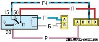
The breaker is connected according to the diagram shown in Fig. 53.
On the scale of microammeter 2, zones are marked that correspond to the permissible values of the angle of the closed state of the contacts for breakers with four, six and eight cam protrusions at a certain frequency of rotation of the breaker shaft (for example, 1500−1 min). Resistor 6 is selected when calibrating microammeter 2 depending on the rotation speed at which the angle of the closed state of the contacts is measured. The larger this angle, the greater the average current passing through the microammeter, and the greater the angle the instrument arrow will deflect. When the breaker shaft is stationary and the breaker contacts are closed, the microammeter needle deflects to the full scale. A variable resistor ensures the accuracy of microammeter 2 settings depending on the battery voltage and the state of the breaker contacts. To adjust the angle of the closed state of the contacts at a certain speed of rotation (at which the marks were applied), loosen the screw securing the fixed contact holder and, by smoothly rotating the adjusting eccentric, align the arrow of the device with the corresponding zone on the scale. Industrially manufactured devices and stands allow such checks and adjustments to be made regardless of the rotation speed of the breaker shaft, which greatly simplifies the check.
Square wheels | Topic author: Flawiusz
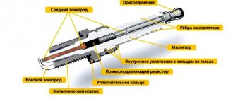
DEVICE AND FUNCTIONS OF THE VAZ 2106 IGNITION COIL IN THE CAR IGNITION SYSTEM. The VAZ 2106 ignition system kit includes:
ignition coil VAZ 2106; distributor; candles; low and high voltage wires and lock. As an addition, the system includes a VAZ ignition relay.
Components of the ignition system of a VAZ 2106 car Previously, a R-125B brand distributor was installed on the car. This unit was mounted on the machine together with a carburetor marked 2103. The distributor had a special mechanical corrector in its design, and there was no vacuum regulator. The VAZ 2106 is equipped with spark plugs of type A17DV or plugs that have similar technical characteristics. The design of the automotive system uses a VK347 type lock, equipped with an anti-theft device. The car uses a B117-A type ignition coil, which has an open magnetic circuit and is oil-filled and sealed. The VAZ 2106 ignition is contact-based, but it is worth noting that sometimes there is also a contactless version of the system. The contact system is considered simpler in its design. VAZ contact ignition requires regular maintenance and monitoring of the condition of the contacts.
It is generally accepted that the contact ignition used on this car is a classic version of the system. The design of the VAZ 2106 spark plugs is non-separable and has a ceramic insulator.
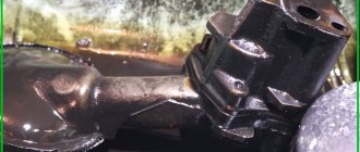
Ignition distributor VAZ 2106 Distributor is designed to interrupt low-voltage currents in the primary winding and distribute high-voltage pulses across spark plugs. The distributor breaker consists of a cam with four protrusions and a stand on which contacts are located that open during rotation. At the upper end of the cam bushing, a support strip of the advance regulator with weights is soldered. A vacuum regulator is attached to the side of the distributor. The design of the distributor provides for the installation of an interference suppression resistor. The operation of the contactless system is based on the use of an electrical impulse distribution sensor. The sensor operates using the Hall effect. It consists of a semiconductor wafer, a special chip and a magnet.
Ignition switch
The ignition switch-lock is installed on the front body panel and consists of two main parts: the switch and the lock, located in a common housing.
Fig. 62. Ignition switch.
The ignition switch is used to turn on and off the current in the primary circuit of the ignition system. At the same time, the circuits of the battery charge indicator light and the gasoline level indicator in the tank are turned on and off accordingly.
The ignition switch (lock) device is shown in Fig. 62. In the housing S of the switch there is a lock cylinder 9 with five cylinders 10 that lock it in the housing. The cylinder can only be turned with a special profile key inserted into it. When the key is turned clockwise from a vertical position until it stops, cylinder 9 turns contact plate 3 by means of driver 6 and insulator 5. In this case, the contact plate connects the current-carrying terminal AM with terminals KZ and PR, as a result of which the ignition is turned on, the indicator light on the front panel, indicating that the battery is being discharged, and the gasoline level indicator circuit is closed. The insulator rotates the contact plate through the shank 11, which fits into the PZZ on the contact plate.
Under the force of the spring 4, the plate 3 is pressed against the pad 2 of the contact insulating panel 12. Three holes are punched in the pad 2, into which the protrusions 1 of the plate 3 fit, holding the latter in the switching position. When the contact plate is rotated to the on position, its protrusions come into contact with the ends of the terminals 14 and are held in the terminals by means of conical chamfers 13.
When the ignition switch is in the zero position, the SC and PR terminals are not energized.
The ignition switch housing is attached to the front panel panel with nut 7.
Uneven sparking
Electrical power distribution in an automotive system is provided by the rotor. It is sometimes put on the distributor drive. And of course, the cover with the CG and sockets for the armored wires is responsible for the correct distribution.
The current distribution in this case can be represented as follows:
- The current flows through a carbon contact with a spring to the rotor.
- Further along the runner tire to the side contact.
- From here to the armored wires of the engine cylinders.
According to experts, in the correct understanding there is no contact between the spark plug sockets and the rotor. Current transmission with a force of 15-25,000 V occurs through an air gap.
But even this design, seemingly simplified to the maximum, suffers from shortcomings. And in particular, cracks and contamination, invisible to the naked eye and immediately, can not only cause current to be diverted to ground. Because of this, the contacts burn out, making it difficult to start the engine, especially in wet weather.
Some distributors are equipped with “interference suppressors”, but they also often burn out. Our skillful guys came up with a bug jumper, but the latter doesn’t always save you.
It is noteworthy that the parts of the contact distributor cannot be restored, except for the rotor side contact. Over time, erosion “eats” it, and by soldering a brass strip, adjustment can be achieved.
Now you know the reason for the burning of the CG or contact group. By eliminating the causes that contribute to this, you can solve the problem quickly and clearly.
Should this be the case? Or is something wrong? Where to look? Is the ignition quality deteriorating significantly? PS: what to do and who is to blame?