avtoexperts.ru
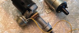
One of the most important parts of a gasoline engine is the distributor, officially called the ignition distributor.
Thanks to the distributor, electrical impulses are supplied to each spark plug separately. As a result, a discharge and corresponding ignition of the fuel mixture are produced in each chamber of the piston. The nature of the work to date is not much different from the first prototypes.
The type of device, its dimensions, dimensions, and “fit” in the engine compartment may change, but the task of distributing discharges among the cylinders will not change. Keep in mind that there is much more than one cylinder in a car, which is why a distribution mechanism is required that evenly divides the charge among the “compartments.”
Remember the main thing, the functioning of some internal combustion engines of the gasoline or gas cycle is impossible without a distributor. In modern cars they try to get rid of them, due to their lack of reliability. They are replaced with individual coils (ignition modules), attached to the spark plug separately or in pairs. As we already understood, they are designed in modules containing from two to four coils. Having got rid of the distributor, the current began to be supplied directly from the ECU through transistor switches, which alternately transmitted 12 V to the coils. From the last impulses “went” to the candle. In this case, controllers control the coils. Thanks to various sensors, the ECU receives and analyzes information about the engine, and based on this it sends the necessary signal to the module. Modern models from manufacturers Mercedes, BMW, Skoda, Citroen, Peugeot, Honda, Subaru and others are equipped with such ignition modules.
Device
There are two dispenser options, contact and non-contact. The design of both is basically identical, with the exception of a couple of nuances. First, let's analyze the contact system. It is important to understand the configuration of only the main components:
1. The housing into which the shaft is inserted, also known as the device drive.
2. The drive, often called a rotor, is due to the existing gear, which is in engagement with the shaft (also known as an intermediate shaft that adjusts the speed) or directly with the camshaft. It all depends on the design and modification of the motor.
3. Coil with winding.
4. Breaker, with a group of terminals and a pair of couplings or a Hall sensor, depending on the specification.
5. The runner is a dielectric that is attached to the shaft and rotates with it. A discharge is transmitted to it, which, through a contact (bunny) on the lid, “goes” to the high-voltage wires.
6. In older cars (VAZ, Moskvich, Volga, some foreign cars), there is an octane corrector that allows you to adjust the shaft speed, depending on what octane number of gasoline is used.
In addition, in addition to the listed elements, there is also a voltage regulator. It protects the contacts from excess current, since part of this charge is absorbed by the capacitor.
Many people will probably want to know how this system works. So, at the moment when the driver turns the key, the circuit closes and the voltage is sent to the starter. That, in turn, thanks to the bendix (a kind of gear) engages with the flywheel crown, causing the rotation of the crankshaft to be transmitted to the distributor. Next, a short circuit occurs in the windings and a low-voltage current is formed, after which the terminals open, and a high-voltage current appears on the secondary circuit, flowing to the cover, through the contact, and then, accordingly, the voltage is transmitted to the “armor”. This type of operation and type of device are typical for models from VAZ, Moskvich, and some old foreign cars from BMW and Fiat.
But, do not forget about more modern versions of the distributor, with a non-contact ignition system, paired with a pulse regulator, instead of a breaker. Not infrequently, owners of domestic cars VAZ 2110, 2107, Gazelles installed contactless distributors. There are three types in total, but only the Hall sensor has become widespread in the automotive industry.
It includes a magnet, semiconductor wafers with chips, as well as special gate systems that allow the magnetic field to pass through.
The Hall sensor completely replaces the breaker that was used in the first versions of the unit. The regulator must be paired with a device such as a commutator, that is, it performs the task of breaking the circuits in the coil.
In general, the principle of operation is completely similar. The rotating crankshaft acts on the distributor with the regulator, the latter generates pulses and transmits them to the switch. And the commutator already creates voltage in the coil itself. Next, the voltage is received by a distributor that directs it along the armor wires. Such devices are typical for models from Skoda, BMW (previous years), Toyota and others, and modern models from VAZ are also equipped with this type of ignition.
Distributor malfunctions
There are more than enough problem areas for such a part, given its complex work in the car system. Any part can fail. So:
• Problems with the lid. Malfunctions can be associated with damage to the cover, such as mechanical damage, for example, a crack or the formation of oxide on the contacts.
It is not uncommon for the “bunny” to break; the only solution for this is to buy a new cover.
Oxidized parts will have to be cleaned with an alcohol solution and dried. Often the problem is due to excess moisture in the area, so make sure there is no moisture there.
• The most common problem with distributors is the slider. The fuse-resistor may blow.
• Capacitor. If it is faulty, increased current is supplied to the spark plugs.
• Another malfunction that occurs rarely, more often after serious mechanical damage. It consists of a change in the plane of rotation of the shaft, its deflection or jamming. The only solution is to replace the entire part.
• Wear of the housing itself, a malfunction as such, is rare, because, as in the previous case, the cause is mechanical damage to the unit. The solution is a complete replacement.
How to check if it's working properly?
There are several ways to check the functionality of a node, some of which directly indicate problems with a particular part. For example, if you have any doubts about the correct operation of the capacitor, checking it is quite simple.
We disconnect it and touch the ground, if a cracking sound is heard, then the part is working. If there is no cracking or other noise, a replacement is needed.
It is more difficult to check the condition of the internal parts, especially the old version. Some signs may indicate malfunctions or complete wear of some parts. For example, loss of power, loss of idle (idling), the appearance of jerks may indicate problems with couplings, bushings, and contacts on the breaker.
Check the contact group, the gaps between them, the condition of the wire insulation, and the condition of the terminals. Don’t forget to check the slider, because in fact it is the one that transmits the current to the wires. The check is quite complicated. You need:
• Remove the slider and small wire and strip it on both sides.
• Wrap one end of the runner plate, secure the other to the ground.
• Next, bring the tip of the armored wire to the plate.
If a spark appears, then the unit is working; if not, replacement will be required because the resistor, which serves to connect the two plates of the runner, has failed.
In other cases, the check may consist of a visual inspection, for example, burnout of the cover, damage to the body, etc., can be easily diagnosed externally, without the need for a detailed analysis of the unit.
Source
What is called ignition timing: main points
The fuel mixture in the cylinder ignites quickly, but not instantly - a certain amount of time passes (about a second) from the moment the spark is formed and the gases expand until the system is activated. During this time, the piston has time to fire, travel the necessary distance and take part in the ignition process. In order to understand what is called the ignition timing angle, it is necessary to understand how the car ignition system as a whole works.
The moment of ignition occurs at the moment when the piston is on the compression stroke and gradually, smoothly approaches TDC. Then the combustion process occurs of a mixture formed from air (not pure oxygen) and gasoline (or diesel fuel, depending on the type of engine used), which form gases characteristic of the reactions taking place. They actively and without stopping push the piston entering the assembly in a downward direction - this moment is called the power stroke.
The energy generated (released) at the moment of direct combustion transforms into another form - mechanical energy that directly starts the crankshaft. The moment of ignition in 95% of cases is determined by its position relative to TDC. In various diagrams or graphs that discuss this process, it is customary to denote the angle in degrees.
All work is divided into several actions that must be performed sequentially. Their order is as follows:
- The engine will need to be turned off (it must cool down if the problem occurs on the road);
- Control is carried out to ensure that the car does not stand in gear (a standing brake is used for this);
- The car key is removed from the ignition;
- You will need to search for marks that should be located next to the timing belt gear;
- The same mark is revealed on another part - the flywheel;
- Then the adjustment of the ignition timing continues - it is necessary to disconnect the wire (it is high-voltage, you should remember this) that approaches the spark plug from the cylinder closest in distance to the radiators (the first one);
- You will need to insert a new spark plug into the wire;
- For convenience, it should be attached to a ground, which may be a hose holder that supplies fuel, located on the valve cover;
- Next you will need to remove the cover from the toggle switch;
- The crankshaft key is placed on the nut located on the flywheel (the operation is performed on the left side of the car);
- The crankshaft will then need to be turned towards you! (if you twist away from you, the flywheel will unscrew);
- While rotating the flywheel, it is necessary to observe the distributor slider, adjusting its position if necessary so that it is in the contact area of the first cylinder.
How to set the ignition timing You should also take into account the values for the marks:
- long – 00;
- average length – 50;
- short – 100.
They vary and depend on the type of engine and make of the car.
The motor must remain off (not running). Next steps:
- The nut securing the toggle switch is released (it, in turn, turns counterclockwise);
- Then the toggle switch turns, but in a clockwise direction (you will need to perform the action until a spark jumps) It is recommended to repeat the action 2-3 times;
- The toggle switch is fixed in the position where the spark appears;
- The wire (high voltage) is returned and attached to the spark plug of the first cylinder.
The final step is to check the ignition timing setting visually and then during actual movement (driving a car).
Attention! Before the first movement after adjustment, it is necessary to warm up the engine to the recommended (operating) temperature. How to disassemble the mechanism at home, see the video below (the author of the video is Roman Romanov)
How to disassemble the mechanism at home, see the video below (the author of the video is Roman Romanov).
Why does the VAZ-2107 twitch - let’s understand the operation of the “distributor”
Well, if the engine of your VAZ-2107 suddenly stalls and does not start, we will find the reason and eliminate it quickly. Everyone knows that this happens if the “spark” disappears or there is no gasoline supplied at all. It’s much worse when the car seems to be moving, but the nerves are fraying - uneven idling, jerking and twitching when driving. Finding the root of the problem can take a lot of time and take a lot of money out of your pocket. And more often than not, these searches ultimately lead to a distributor. This material will help you correctly replace it with a working one, select a suitable replacement, and understand the device and operation. Before delving into the “electrics”, it must be said that the reason for the “jerking” of the VAZ-2107 and other “classic” VAZ models may be an unsuccessful combination of the clutch driven disc damper and the elastic coupling of the driveshaft. Spare parts are supplied with parts whose characteristics may differ greatly from the factory ones, therefore, if the “jerking” intensifies after replacing the clutch or “soft connection”, you need to look for the cause there. Try installing a unit from another manufacturer - its characteristics will be different, the resonance in the transmission will disappear and the “jerking” will stop.
How to check the distributor
The most common manifestations of an ignition malfunction will be as follows:
- floating idle;
- engine that won't start;
- engine stalling while driving.
Most often, the cause of this may be the distributor. The easiest way to check the performance of the ignition, including the distributor, is as follows. To do this, unscrew the spark plug, bring it to the engine and start it, observing the appearance of a spark. If it is not there, then you need to check the functionality of the high voltage wires. If there is no spark again, then the diagnosis is clear - the distributor has failed.
In this case, you need to visually check the condition of the slider, the condition of the contacts and the distributor cover. Burnt contacts are cleaned and dust and debris are removed from the internal surfaces of the distributor. In a workshop or garage, you can check the performance of the ignition and distributor using measuring instruments and indicators.
The distributor appeared on the car almost simultaneously with the gasoline engine, and for many years remained almost unchanged, including on domestic cars of the 2109, 2106, 2107, 2108 family. And only after the advent of a modern element base, which includes the Hall sensor, gave way to contactless and then microprocessor ignition systems. » alt=»»>
Ignition malfunctions of the VAZ 2107, regardless of the type of system itself (contact or non-contact), are often associated with a distribution switch (distributor). Despite its complex electromechanical design, almost any breakdown can be fixed with your own hands.
What signs indicate a malfunction of the VAZ car distributor?
1. The engine does not start: - there is no gap or too large a gap between the breaker contacts; -burnt and dirty contacts; - the capacitor has failed; - the noise suppression resistance of the “slider” has burned out; - the distributor cover is “broken”; - the low voltage wire is broken or its terminals are oxidized; -Hall sensor burnt out (non-contact ignition). 2. The engine “shakes” at idle: - the gap between the contacts is not normal; - ignition too early. 3. The engine “jerks” at high speeds: - the gap between the breaker contacts is too large; - the spring of the movable contact of the breaker has weakened; - the springs of the centrifugal regulator have weakened. 4. “Jerking”, interruptions in all engine modes: -damage to high voltage wires, oxidized or loose in the sockets; -dirty, oily, burnt breaker contacts; - the corner of the moving contact in the distributor cover is worn out or broken; -cracks and burnouts of the “runner” and the distributor cover; - the capacitor is “half broken” and needs to be replaced; - the bushings are worn out and the distributor shaft is “playing”; - the contactless ignition system switch is faulty. 5. The car accelerates slowly, consumes a lot of fuel: -the ignition timing is incorrectly set. Note! Signs of a malfunction of the VAZ-2107 distributor are very easily confused with manifestations of malfunctions in the power system . Therefore, never start disassembling the distributor and carburetor with the fuel pump at the same time!
VAZ 2106 distributor contacts are burning
From personal experience - when the KSZ was installed, the jerking was due to an incorrectly set gap. The capacitor never burned. The solution is a BC with an UZSK angle, using it you can very accurately set the UZSK without resorting to any probes, etc. What else I think: most likely the distributor bearing is broken, because of this there was a large radial displacement of the slider, it hit the cover and it flew off. And secondly, most likely the slider itself was screwed on poorly, and if the bearing really shattered at high speeds (if the distributor is especially hairy), the vibration caused the screws to unwind and goodbye to the slider.
In my opinion, there is only one solution - KSZ in the firebox, BSZ under the hood. The cost of the issue is ridiculous - not going to the bar with friends a couple of times. I bought it myself on a scholarship when I was still studying.
PySy topic for demolition, then use the search. Verbal warning =)
From personal experience - when the KSZ was installed, the jerking was due to an incorrectly set gap. The capacitor never burned. The solution is a BC with an UZSK angle, using it you can very accurately set the UZSK without resorting to any probes, etc.
What else I think: most likely the distributor bearing is broken, because of this there was a large radial displacement of the slider, it hit the cover and it flew off. And secondly, most likely the slider itself was screwed on poorly, and if the bearing really shattered at high speeds (if the distributor is especially hairy), the vibration caused the screws to unwind and goodbye to the slider.
In my opinion, there is only one solution - KSZ in the firebox, BSZ under the hood. The cost of the issue is ridiculous - not going to the bar with friends a couple of times. I bought it myself on a scholarship when I was still studying.
PySy topic for demolition, then use the search. Verbal warning =)
If you can, go through the distributor completely (according to the manual), lubricate it with oil.
Test. Replacing the standard distributor capacitor with a polypropylene one. Standard 0.22 uF x 400 volts. Replacement with polypropylene 0.28 uF x 1000 volts. The indicators do not fall over time, there are almost no leaks. The original capacitor shows incredible performance results. The real capacity is underestimated by three times (which goes wrong) and there is a crazy leak, as a result of which the contacts burn out. It doesn't serve any purpose, it costs a dollar and a half. 10 hryvnia. 40 rubles.
Distributor function in the ignition system of a carburetor car
The full name of this device “ignition switch-distributor” reveals part of its “responsibilities” - at a strictly defined time to break the low-voltage circuit of the ignition coil and distribute the resulting high-voltage energy, in a given order (1-3-4-2), among the cylinders . It is also “responsible” for changing the ignition timing depending on the speed of the engine crankshaft (crankshaft) using a centrifugal regulator and “correcting” this angle depending on the load on the engine using a vacuum corrector.
Operating principle of the distributor
UAZ contact ignition system, composition and general structure, diagrams of the contact ignition system.
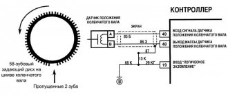
procedure for installing the ignition on a UAZ car; wiring diagram for electronic ignition on a UAZ. In many ways, the operating principle of the distributor remained unchanged for many years. In VAZ cars, such as VAZ 2109, 2106, 2107, 2108, an ignition system of this type was used almost until the end of the last century.
The basis of the work is the connection of the distributor with the engine crankshaft. When the piston in the first cylinder takes the position corresponding to TDC, the breaker contacts open, a high voltage appears in the ignition coil, directed through a slider located in the distributor cover to the spark plug of the first cylinder.
There the combustion of the fuel assembly occurs, and the crankshaft continues to rotate. In addition to moving the pistons, it causes the breaker cam to rotate. When in another cylinder another piston occupies a position corresponding to TDC, at this moment the breaker contacts in the distributor open again, and a high-voltage voltage is generated in the ignition coil and supplied to the desired spark plug.
This joint rotation of the crankshaft, the breaker cam and the distributor slider ensures that a spark appears where and when needed. However, this does not cover all aspects of how the distributor works. To understand its operation, it is necessary to touch upon such concepts as the angle of the closed state of contacts (UZSK) and the ignition timing angle (IAF)
UZSK
A concept such as UZSK characterizes the time when the breaker contacts are closed. In essence, this is an indirect characteristic of the accumulation of energy in the coil after the completion of spark formation. UZSK directly affects the amount of energy spent on sparking and, accordingly, on engine operation.
In cases where the distance between the contacts is small, the coil will not accumulate the necessary energy and the spark energy will be low, which will lead to interruptions in the operation of the motor. A large gap also leads to interruptions, since the contact breaking time is reduced and the coil does not have time to fully discharge.
Each ignition system has its own optimal UZSK, to ensure which, if necessary, the distributor must be checked and adjusted.
UOZ
This concept concerns the moment of ignition of a fuel assembly. The fact is that its combustion does not occur instantly, and often, to ensure optimal conditions for such a process, it must begin earlier than the piston reaches the TDC position. The OZ characterizes the time by which the appearance of a spark precedes the appearance of the piston in the TDC position.
It is constantly changing, and its value completely depends on the operation of the motor under specific conditions, i.e. depending on the load, vehicle speed, quality and type of fuel used. To ensure optimal combustion of the fuel assembly, the distributor contains a centrifugal regulator and is also connected to a vacuum regulator.
VACUUM REGULATOR
It is this device that can change the OZ if necessary. As soon as the motor load changes, appropriate adjustments are made to the operation of the distributor device parts.
Important! The load is determined using the throttle valve.
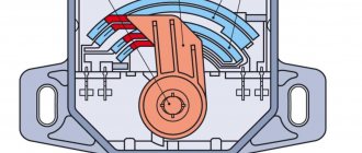
The vacuum regulator of the distributor is a closed cavity. To ensure better performance, the design is divided by a diaphragm. One cavity goes directly to the carburetor.
When a vacuum occurs, the diaphragm begins to move. As a result, pressure is exerted on the movable disk and the breaker cam. The response time of the latter is adjusted depending on the current situation.
Attention! The distributor changes the moment of spark formation, thereby affecting the performance characteristics of the motor.
OCTANE-CORRECTOR
This is a very important element in the distributor design. Without it, the entire system could not function normally. The unit changes the SOP depending on the fuel that is currently being used.
By its design, this distributor element resembles two plates with an arrow. The same arrow is installed on the engine. There are special lines on it, through which the ignition angle is adjusted. It is almost impossible to do without this part when refueling different types of gasoline.
CONTACTLESS SYSTEMS
Technologies do not stand still. Every year, the automotive world is rocked by new innovations. This is precisely what innovation became in its time, supplementing the distributor design with switches.
Attention! In switches, the signal is supplied to the control electronic module, and not to the coil.
The second name for non-contact systems in the distributor device is Hall sensors. The simple design of these devices ensures uninterrupted signal supply. The sensors themselves work due to changes in the magnetic field.
Which distributor is suitable for the VAZ-2107
On all carburetor rear-wheel drive VAZ cars, the device has almost identical components and a similar operating principle. Distributors for engines with a volume of 1200-1300 cc differ in that: - the drive rod is 7 mm shorter; — no vacuum ignition timing regulator; — the settings of the weights and springs of the centrifugal regulator are different. For engines with a volume of 1500-1600 cc, all distributors are suitable in terms of mounting dimensions and characteristics. Only “Nivovskie” ones differ. They are tuned for stable traction at low speeds and the VAZ-2107 with such a distributor will accelerate slowly. The brands of “Nivovsky” distributors are: 3810.3706, 038.3706-10. And distributors of brands 0.3706 (contact) and 38.3706 (non-contact) are suitable for the “Seven” and other classic cars.
↑ Ignition distributor 0.3706
1 — ignition distributor roller; 2 — wire for supplying current to the ignition distributor; 3 — cover fastening latch; 4 — vacuum regulator housing; 5 - diaphragm; 6 — vacuum regulator cover; 7 — vacuum regulator rod; 8 — pipe for the vacuum hose from the carburetor; 9 — lubricating wick (filt) of the cam; 10 — support (driven) plate of the ignition timing regulator; 11 — ignition distributor rotor; 12 — side electrode with a terminal for the wire to the spark plug; 13 — ignition distributor cover; 14 — central terminal for the wire from the ignition coil; 15 — central carbon electrode with a spring; 16 — central contact of the rotor; 17 - resistor for suppressing radio interference; 18 — external contact of the rotor; 19 — driving plate of the centrifugal regulator; 20 — weight of the centrifugal ignition timing regulator; 21 — lever axis; 22 — breaker cam; 23 — breaker lever; 24 — stand with breaker contacts; 25 — breaker contacts; 26 — movable breaker plate; 27 - capacitor; 28 — ignition distributor housing; 29 — roller oil deflector clutch; 30 — bearing locking plate; 31 — bearing of the movable plate of the breaker; 32 — oiler body; 33 — screws for fastening the rack with breaker contacts; 34 — terminal clamp screw; a — groove for distinguishing ignition distributors 30.3706; b - groove for moving the stand with contacts Fig. 8–22. Ignition distributor 0.3706: 1 — ignition distributor shaft; 2 — wire for supplying current to the ignition distributor; 3 — cover fastening latch; 4 — vacuum regulator housing; 5 - diaphragm; 6 — vacuum regulator cover; 7 — vacuum regulator rod; 8 — pipe for the vacuum hose from the carburetor; 9 — lubricating wick (filt) of the cam; 10 — support (driven) plate of the ignition timing regulator; 11 — ignition distributor rotor; 12 — side electrode with a terminal for the wire to the spark plug; 13 — ignition distributor cover; 14 — central terminal for the wire from the ignition coil; 15 — central carbon electrode with a spring; 16 — central contact of the rotor; 17 - resistor for suppressing radio interference; 18 — external contact of the rotor; 19 — driving plate of the centrifugal regulator; 20 — weight of the centrifugal ignition timing regulator; 21 — lever axis; 22 — breaker cam; 23 — breaker lever; 24 — stand with breaker contacts; 25 — breaker contacts; 26 — movable breaker plate; 27 - capacitor; 28 — ignition distributor housing; 29 — roller oil deflector clutch; 30 — bearing locking plate; 31 — bearing of the movable plate of the breaker; 32 — oiler body; 33 — screws for fastening the rack with breaker contacts; 34 — terminal clamp screw; a — groove for distinguishing ignition distributors 30.3706; b - groove for moving the stand with contacts
The main components of the distributor and a description of its operation
VAZ classic distributor device
Device
The distributor is assembled in a housing. Inside it, a contact group is mounted on a bearing: moving and fixed contacts or a Hall sensor (for contactless ignition). To correct the advance angle, the vacuum regulator can rotate the contact group at a small angle relative to the housing. The capacitor is attached to the bottom of the case with screws. A drive roller is mounted on bushings in the center of the body. Its bottom has splines with which it engages with the drive gear. In the upper part of the roller there are contact drive cams (for contact ignition) or a steel cup with four slots - a screen (for contactless ignition). At the very top, on a steel platform, two weights and two springs of the centrifugal ignition regulator are installed. A plastic housing with a moving contact and noise suppression resistance of the high voltage distributor (slider) is screwed onto the top with two screws. The entire structure is closed with a lid on two spring latches. The body and cover have a tongue and groove so that they fit together in only one position. The cover contains contact terminals for high voltage wires from the spark plugs and from the ignition coil. The distributor is secured to the engine block using a stud, nut and pressure washer. To adjust the ignition timing, the housing can be rotated relative to the block.
Job
The distributor is connected through the drive to the engine crankshaft and rotates with it. For two full revolutions of the crankshaft, the distributor shaft makes one revolution. This is due to the fact that our engine is four-stroke. When installing the distributor in place, the roller is oriented in strict accordance with the operating order of the engine. This is done so that the contacts open and the spark jumps on the spark plug when the piston of each cylinder, compressing the combustible mixture, does not reach top dead center (TDC) by a few millimeters. This is called ignition advance. When the number of revolutions increases, the distance must be increased, and when it decreases, it must be decreased, which is what the centrifugal regulator does. Its weights, under the influence of centrifugal force, which is greater the higher the engine speed, diverge to the sides and move the cams relative to the roller, making ignition “earlier.” When the engine speed decreases, the springs return the weights to their place and the ignition becomes “later”. This is necessary to increase engine power and efficiency. In addition to the centrifugal one, a vacuum ignition timing regulator is also installed on the distributor. Its function is to fire “earlier” at low throttle opening angles and “later” at sharp throttle opening angles. At idle and at full throttle, the vacuum seal does not work. The regulators are adjusted only at the stands, so there is no need to change the settings yourself.
Installation and adjustment of the distributor
On a VAZ 2106 car, repair of the distributor is necessary if it is not working correctly, but if this element is working normally, in order to set it correctly, you first need to set the marks. The crankshaft rotates either by a ratchet or by a nut using a special wrench. You can see marks on the power unit cover.
To set the ignition correctly, the marks must be correctly aligned:
- The established first meta in the direction of travel represents an advance of the angle by ten degrees. This parameter is relevant for cars using 72 fuel.
- The mark located in the middle is an advance of the angle by five degrees, which is optimal for cars running on 80 gasoline.
- The last mark represents a lead angle of 0 degrees. This means that the combustible mixture will be ignited while the piston is at TDC. When setting tags, you need to take these nuances into account.
When you finish making marks, you need to set the required gap in the contacts. To do this, the runner of the distribution unit must be removed and the fixing bolt of the interrupting element must be unscrewed. It is recommended to clean the contacts in advance using sandpaper. When open, the gap on the contacts should be no more than 0.4 mm.
Identification of marks on the device
Before doing this, you need to unscrew the mount of the distribution unit using a wrench, then it can be removed from the housing.
To ensure that the installed unit works correctly, consider the following nuances:
- The adjustment was made at the TDC mark on the 1st cylinder, so that at the moment the spark should appear in it. To catch this moment, you need to install the VAZ 2106 distributor cover and mark the place where the high-voltage spark plug cable from the first cylinder enters. Then it is necessary to dismantle the cover, after which the external contact of the slider is installed opposite the mark.
- After this, in order for the power unit to operate in normal mode, you should draw a conventional line between its clamps and place the mechanism in the installation location so that this line is parallel to the motor block. It should be noted here that it is not always possible to get into the splines right away; it may be necessary to rotate the body a little to do this. In principle, this is not a problem, since in the future the ignition will still need to be adjusted. You need to ensure that the mechanism can completely sit in the installation location, right until the moment it completely rests on the block. Having done this, the knot can be pulled into place (the author of the video is Andrey Gorinov).
Removal and installation of distributor VAZ-2107, 2104, 2105, 2106
Preparation
Before installing a new VAZ-2107 distributor for a contact ignition system, you need to adjust the gap between the contacts of the breaker. It is more convenient to do this with the device removed from the car. We check the gap with a flat feeler gauge. The value is set from 0.35 to 0.45 mm. In this case, the protrusion of the cam should move the moving contact away from the stationary contact as much as possible. We adjust by slightly loosening the screws, and then tighten them more firmly and check the gap again. Contacts that have worked hard may have a protrusion on one and a depression on the other, which interferes with adjustment. You can get around this problem by grinding off the protrusion with a needle file. It is better not to use sandpaper, because... small particles of abrasive will definitely “eat” into the surface and interfere with the operation of the contacts.
Before removing the old distributor, mark its position relative to the cylinder block with a marker. You also need to accurately mark the position of the moving contact (slider) relative to the body. If all this is not done, the settings will be violated and the engine will not start.
Installation
Having established exactly the same position of the roller in the body on the new distributor, carefully insert it into the hole in the block, slightly turning the roller to align the splines. Having “planted” the device in place by rotating the body relative to the block, we set the approximate advance angle, as on the old distributor. Secure with a washer and nut, but not too tight. Now you need to plug in the high voltage wires. This is easy to do - each contact on the distributor cover has the number of the cylinder to which it needs to be connected. We connect the wire from the ignition coil to the central terminal. The wires should fit tightly, with a slight tension, the protective caps should be pushed all the way down. Don’t get carried away, don’t bend the petals of the wire tips too much, otherwise later, when you try to remove them, you’ll tear off the wires “with their roots”! A wire goes from the contact wire to the “K” terminal of the ignition coil, usually it is green. If your VAZ-2107 is equipped with a contactless ignition system, then you need to connect a connector with three wires. Having plugged it into the socket, check the fit of the wires; it happens that they “crawl out” from their places and the device does not work. Everything is done, the new distributor is installed and ready to go. Let's try to start the engine. Started up? Great, that means everything was done correctly, all that remains is to check and slightly adjust the ignition timing.
Adjusting the ignition on a VAZ 2106.
Suspension bearing for the propeller shaft VAZ 2107 (2105, 2106, 2101) - replacement with photos and videos
If the car is equipped with a classic ignition system, then before starting the adjustment, it is advisable to clean the contacts of the distributor with a file. After cleaning, we check the condition of the contacts - you need to make sure that the contacts are in contact with each other along the entire plane.
If the need arises, the contacts will have to be adjusted. Now we turn the crankshaft to a position at which the distance between the contacts is maximum. We unscrew the screw that secures the contact group on the bearing plate,
now we insert the probe - its thickness should be approximately 0.4 mm between the contacts,
Afterwards, the position of the contact group is selected, at which the probe will move with little effort; this position must be fixed.
We check the size of the gap with two probes; a thick probe will not be able to pass into the gap between the contacts, and a thin one will move without any effort. In order to rotate the crankshaft, it is advisable to use a special key.
If this is not the case, then put it in fourth gear and carefully push the car. You won't be able to use a starter because it's almost impossible to get the right angle of rotation. The gap resulting between the contacts of the distributor gives the necessary value to the UZSK, do not forget that the angle is critical, not the gap! It is precisely because of this that you need to check the adjustment by measuring the angle, which is approximately 55±3°
.
The simplest option is to use an electronic tachometer, which has a UZSK measurement function. To use this device, you need to assemble the distributor and start the engine. The tachometer must be switched to UZSK measurement mode.
If the UZSK goes beyond the limits recommended by the manufacturer, the gap adjustment will have to be repeated. There is another way, in which you need to measure the angle. The first thing we do is pull out the central explosive wire from the distributor cover and hook it to the ground of the car, you don’t have to pull out the wire, but then there will be a risk of a breakdown in the coil. To the wire going from the distributor to the ignition coil, you will need to connect 12- Ti volt light bulb.
The light will light up if the ignition is on and the distributor contacts themselves are open, and go out when they are closed. If a thyristor or transistor system is installed on the car, then the light bulb will not light up when the contacts are open, due to the fact that there is a current limiter. Then the light bulb will have to be replaced with a voltmeter; in the open contact position it shows 12 V, and in the closed position - 0.
We turn the crankshaft clockwise, you need to turn it until the contacts close. We remember this position of the slider; it is advisable to mark it on the distributor. The crankshaft must be rotated until the contacts open.
We remember this position of the slider, then measure the angle between these two positions. This is done like this: we measure the length of the circular arc using the distributor body, then calculate the angle in degrees using the formula:
(360pd)/l in which:
- p=3.14 - Pythagorean number;
- d=70 mm - diameter of the distributor body;
- l, mm - measured length of the arc along the distributor body between the marks.
If the UZSK is set correctly, the arc length will be 33±2 mm.
Now let's move on to the second stage. It consists in adjusting the advance angle.
For engines of VAZ-2103, VAZ-2106 cars, the moment of opening the contacts of the distributor-chopper, which corresponds to the spark of the 1st cylinder, is ahead of the top dead center of the piston of the first cylinder by 0±1°. Several adjustment methods are described below.
Checking the ignition timing of the VAZ-2107 engine
The methods described below make it possible to independently adjust the ignition timing. They are suitable equally well for both contact and non-contact distributors. We adjust the ignition timing at idle speed . We warm up the engine to operating temperature, at idle speed, turning the body relative to the block, “catch” the position in which the speed will be the highest. We fix the distributor in this position. We check the correct setting of the ignition timing “on the fly”. Having looked at a free section of a flat road, we drive out onto it. We keep the speed at 40 km/h in fourth gear and sharply press the gas pedal. a loud metallic knock should be heard under the hood, disappearing by itself after a few (four to six) seconds. Is everything exactly like this for you? This means the adjustment is complete. If the knocking does not go away for a long time, we stop, loosen the distributor and turn the distributor clockwise a couple of millimeters, making the ignition later. We start the engine again, accelerate, and repeat the test. If there is no knocking at all, then the distributor needs to be turned counterclockwise, setting the ignition “early” and checked again while driving. After doing these steps several times, you get the optimal ignition timing specifically for your VAZ engine. Still have questions? Watch this video
Source
Contactless systems and Hall sensor in the distributor
The distributor described above is a classic version and was used for many years on all cars, including the VAZ family, such as 2109, 2106, 2107, 2108. However, as electronics developed, voltage switches began to appear in which the breaker signal was used not for switching the ignition coil, but for controlling the electronics. Later, the distributor lost its mechanical breaker and was replaced by a Hall sensor.
The Hall sensor used has a fairly simple design. Yes, it must be recalled that the Hall sensor is an element that responds to a magnetic field. Therefore, the design of the sensor using Hall elements is based on this principle. To do this, a Hall sensor is located directly on the plate, on the other side there is a permanent magnet, and between them there is a rotating metal screen in which special slots are made.
When the screen blocks the field from the installed magnet, the Hall sensor has zero voltage at the output; when windows are opened instead of a solid screen, the Hall sensor generates a high voltage at the output. The distributor transmits this generated sequence of pulses to the voltage switch, and it controls the ignition coil.
Purpose and types of distributors
The main distributor of the “six” is located on a horizontal platform made to the left of the engine valve cover. The unit shaft, ending with splines, enters the drive gear inside the cylinder block. The latter rotates by the timing chain and at the same time rotates the oil pump shaft.
The distributor performs 3 functions in the ignition system:
The spark is supplied and the air-fuel mixture is ignited before the piston reaches the upper extreme point, so that the fuel has time to fully burn. At idle, the advance angle is 3-5 degrees; with increasing crankshaft speed, this figure should increase.
Various modifications of the “sixes” were equipped with different types of distributors:
The difference in the length of the drive shaft, depending on the height of the cylinder block, does not allow the use of the VAZ 2106 part on a 1.3 liter engine - the distributor simply will not fit into the socket. Installing a spare part with a short shaft on a “clean six” will also not work - the splined part will not reach the gear. The rest of the filling of the contact distributors is the same.
As a young, inexperienced driver, I personally encountered the problem of different lengths of ignition distributor rods. On my Zhiguli VAZ 21063, the distributor shaft broke off on the road. At the nearest auto store I bought a spare part for the “six” and began installing it on the car. Result: the distributor was not inserted completely; a large gap remained between the platform and the flange. Later the seller explained my mistake and kindly replaced the part with one suitable for the 1.3 liter engine.
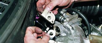
Removing the replacement part
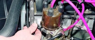
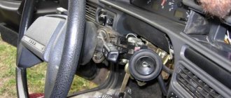
Be sure to remove the terminal from the battery! After this, we disconnect all kinds of wiring from the coil, the main high-voltage wire. Now remove the cap from the distributor.
We must try to set the slider so that it is at an angle of 90 degrees towards the engine.
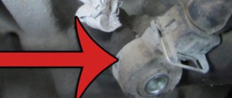
Draw a mark in advance (most conveniently on the cylinder block) so that you screw the new part to its original location.
Unscrew the nuts from the old distributor and remove it.
Maintenance of contact type distributor
In order to repair the distributor yourself, you need to understand its structure and the purpose of all its parts. The operating algorithm of the mechanical distributor is as follows:
In fact, 2 electrical circuits pass through the distributor - low and high voltage. The first is periodically broken by the contact group, the second is switched to the combustion chambers of different cylinders.
Now it’s worth considering the functions of the small parts that make up the distributor:
An important point should be noted: a manual octane corrector is found only on older versions of R-125 distributors. Subsequently, the design changed - instead of a wheel, an automatic vacuum corrector appeared with a membrane operating from engine vacuum.
The chamber of the new octane corrector is connected by a tube to the carburetor, the rod is connected to the movable plate where the breaker contacts are located. The magnitude of the vacuum and the amplitude of the membrane operation depend on the opening angle of the throttle valves, that is, on the current load on the power unit.
A little about the operation of the centrifugal regulator located on the upper horizontal platform. The mechanism consists of a central lever and two weights with springs. When the shaft spins to high speeds, the weights move apart under the influence of centrifugal forces and turn the lever. The interruption of the circuit and the formation of a discharge begins earlier.
Typical faults
Problems with the ignition distributor manifest themselves in one of two ways:
In the second case, the fault is easier to detect. The list of reasons leading to complete failure is relatively small:
A fracture of the shaft leads to complete failure of the VAZ 2106 engine. Moreover, a fragment with splines remains inside the drive gear, as happened on my “six”. How to get out of the situation while on the road? I removed the distributor, prepared a piece of cold weld mixture and stuck it to a long screwdriver. Then he lowered the end of the tool into the hole, pressed it against the fragment and waited for the chemical composition to harden. All that remains is to carefully remove the screwdriver with a piece of the shaft stuck to the “cold welding”.
There are many more reasons for unstable operation, so they are more difficult to diagnose:
The resistor and capacitor are checked using a tester; the broken insulation of the cover and slider is detected without any instruments. Burnt contacts are clearly visible to the naked eye, as are stretched weight springs. Diagnostic methods are described in more detail in the following sections of the publication.
Tools and preparation for disassembly
To repair a VAZ 2106 distributor yourself, you need to prepare a simple set of tools:
If you plan to completely disassemble the distributor, it is recommended to stock up on aerosol lubricant such as WD-40. It will help displace excess moisture and make it easier to unscrew small threaded connections.
During the repair process, you may need additional equipment and materials - a multimeter, a bench vice, pliers with pointed jaws, motor oil, and so on. There is no need to create special conditions to carry out the work; the distributor can be repaired in a regular garage or in an open area.
To avoid problems with setting the ignition during assembly, it is recommended that before removing the element, fix the position of the slider according to the instructions:
To dismantle the distributor, you need to disconnect the vacuum tube from the membrane block, disconnect the coil wire and unscrew the only fastening nut with a 13 mm wrench.
Problems with the lid and slider
The part is made of durable dielectric plastic; in the upper part there are terminals - 1 central and 4 side. High-voltage wires are connected to the sockets from the outside; from the inside, the terminals are in contact with a rotating slider. The central electrode is a spring-loaded carbon rod in contact with the brass rotor pad.
A high-potential pulse from the coil is applied to the central electrode, passes through the slider contact pad and resistor, then goes to the desired cylinder through the side terminal and armor wire.
To identify problems with the cover, it is not necessary to remove the distributor:
Don't be afraid to mix up high-voltage cables when disconnecting. On the top of the cover there are cylinder numbers, which are easy to navigate.
An insulation breakdown between two contacts is diagnosed as follows:
Not knowing such subtleties, I went to the nearest auto store and bought a new cover with the condition of return. Carefully swapped parts and started the engine. If the idle speed leveled out, I left the spare part on the car, otherwise I returned it to the seller.
The slider malfunctions are similar - abrasion of contact pads, cracks and breakdown of the insulating material. In addition, a resistor is installed between the rotor contacts, which often fails. If the element burns out, the high-voltage circuit is broken and a spark is not supplied to the spark plugs. If black marks are detected on the surface of a part, its diagnostics is necessary.
Important note: when the slider becomes unusable, there is no spark on all spark plugs. An insulation breakdown is diagnosed using a high-voltage cable coming from the coil. Pull the end of the wire out of the cover, bring it to the central contact pad of the slider and turn the crankshaft with the starter. A discharge appears, which means the insulation is broken.
It's easy to check the resistor - measure the resistance between the terminals with a multimeter. A value of 5 to 6 kOhm is considered normal; if the value is more or less, replace the resistance.
Video: how to check the functionality of the slider
Troubleshooting Contact Group Problems
Since a spark jumps between the contact surfaces when opening, the working planes gradually wear out. As a rule, a protrusion is formed on the movable terminal, and a depression is formed on the static terminal. As a result, the surfaces do not fit well, the spark discharge weakens, and the motor begins to “trouble.”
A part with minor wear is restored by cleaning:
In stores you can find spare parts with modernized contacts - holes are made in the center of the working surfaces. There are no depressions or growths on them.
If the terminals are worn to the limit, it is better to change the group. Sometimes the surfaces are deformed to such an extent that it is impossible to adjust the gap - the feeler gauge is inserted between the bump and the recess, leaving too much clearance at the edges.
The operation is performed directly on the car, without dismantling the distributor itself:
Installing the contacts is not difficult - screw the new group with screws and connect the wire. Next - adjust the gap to 0.3-0.4 mm, performed using a feeler gauge. You need to turn the starter a little so that the cam presses on the plate, then adjust the gap and fix the element with the adjusting screw.
If the working surfaces burn too quickly, it is worth checking the capacitor. Perhaps it has dried out and is not performing its function well. The second option is a low quality product, where the opening surfaces are offset or made of ordinary metal.
Bearing replacement
In distributors, a roller bearing is used for the correct operation of the octane corrector. The element is combined with a horizontal platform where the contact group is attached. A rod coming from the vacuum membrane is attached to the protrusion of this platform. When the vacuum from the carburetor begins to move the diaphragm, the rod rotates the platform along with the contacts, adjusting the moment of sparking.
During operation, play occurs on the bearing, which increases with wear. The pad, together with the contact group, begins to dangle, opening occurs spontaneously, and with a small gap. As a result, the VAZ 2106 engine operates very unstable in any mode, power is lost, and gasoline consumption increases. The bearing is not repaired, only replaced.
The play of the bearing assembly is determined visually. It is enough to open the distributor cover and move the contact breaker up and down with your hand.
Replacement is performed in this order:
Installation of the new element is carried out in the reverse order. Before installing the inside of the distributor, it is advisable to thoroughly clean it. If rust has formed on the roller, remove it with sandpaper and lubricate the clean surface with engine oil. When you insert the shaft into the housing sleeve, do not forget to adjust the contacts according to the feeler gauge.
When installing the distributor, maintain the original position of the body and runner. Start the engine, loosen the nut securing the element and turn the housing to achieve the most stable operation. Tighten the fastening and check the “six” while driving.
Video: how to correctly change a bearing without marking
Other faults
When the engine categorically refuses to start, you should check the functionality of the capacitor. The technique is simple: put an assistant behind the wheel, remove the distributor cap and give the command to rotate the starter. If a barely noticeable spark jumps between the contacts or is not observed at all, feel free to buy and install a new capacitor - the old one can no longer provide the required discharge energy.
Any experienced driver who operates a “six” with a mechanical distributor carries a spare capacitor and contacts. These spare parts cost pennies, but the car won’t run without them. I was convinced of this from personal experience when I had to look for a capacitor in an open field - a passing Zhiguli driver helped me and gave me his own spare part.
Owners of a VAZ 2106 with a contact distributor are also plagued by other minor troubles:
It is not necessary to change stretched springs. Unscrew the 2 screws securing the slider and, using pliers, bend the brackets where the springs are attached. A torn membrane cannot be repaired - you need to remove the assembly and install a new one. Diagnostics is simple: disconnect the vacuum tube from the carburetor and draw air through it with your mouth. A working diaphragm will begin to rotate the plate with contacts through traction.
Video: complete disassembly of the ignition distributor VAZ 2101—2107
↑ Procedure for checking the gap
It is necessary to check the gap between the contacts of the breaker in the following order.
- Place the gear shift lever in neutral and apply the parking brake to the vehicle.
- Remove the cover from the ignition distributor and, by rotating the crankshaft, set the breaker cam to a position in which the breaker contacts are maximally open.
- Check the gap size with a feeler gauge; if it goes beyond 0.35–0.45 mm, then loosen screws 33, insert the blade of a screwdriver into groove “b” and turn the breaker stand to the desired amount.
- After adjustment, tighten screws 33 until they stop.
Source: ovaze.ru
Construction and repair of a contactless distributor
The design of the distributor, operating in conjunction with the electronic ignition system, is identical to the design of a mechanical distributor. There is also a plate with a bearing, a slider, a centrifugal regulator and a vacuum corrector. Only instead of a contact group and a capacitor, a magnetic Hall sensor is installed plus a metal screen mounted on the shaft.
How a contactless distributor works:
The electronic system of the VAZ 2106 uses a different type of coil that can work in conjunction with a switch. It is also impossible to convert a regular distributor to a contact one - it will not be possible to install a rotating screen.
The non-contact distributor is more reliable in operation - the Hall sensor and bearings become unusable much less often due to the lack of mechanical load. A sign of meter failure is the absence of a spark and complete failure of the ignition system. Replacement is easy - you need to disassemble the distributor, unscrew the 2 screws securing the sensor and pull the connecting connector out of the groove.
Malfunctions of the remaining elements of the distributor are similar to the old contact version. Troubleshooting methods are described in detail in the previous sections.
Video: replacing the Hall sensor on classic VAZ models
Why do you need a distributor?
The ignition system is a critical part of a gasoline engine. The operation of the latter is based on the timely combustion of the fuel-air mixture (FA), for which purpose a high-voltage voltage is specially generated, which is then supplied to the spark plugs. A spark is formed on them, causing combustion of the fuel assemblies, as a result of which the engine performs useful work. This is roughly how you can briefly describe the operating principle of a gasoline internal combustion engine.
All these processes require a distributor. If we evaluate its role during the operation of the ignition, it should be noted that it:
- initiates the onset of sparking due to the opening of the breaker contacts (in more modern car models, for example, VAZ 2109, 2106, 2107, 2108 of the last years of production, a Hall sensor is used for these purposes);
- directs the high voltage generated in the ignition coil to the desired spark plug;
- changes the beginning of the moment of spark formation depending on the driving modes and the fuel used, for which vacuum centrifugal regulators are used;
- provides accumulation and discharge of energy in the reel.
Contactless distributor
In "sevens" with a contactless ignition system, a distributor of type 38.3706 is used. As already mentioned, the design of a non-contact distributor is similar to a contact one, with the exception of the mechanism responsible for creating electrical impulses in the low-voltage circuit of the system. Here, instead of a contact group, this function is performed by a Hall sensor. As for the malfunctions of the non-contact distributor, they are the same as those of the contact distributor, therefore, it is not advisable to consider them again. But it’s worth talking about the sensor in detail.
Hall Sensor
The operation of the sensor is based on the phenomenon of induction. The design of the device is based on a permanent magnet and a hollow cylindrical screen with four cutouts in the form of a crown. The screen is fixedly fixed on the distributor shaft. As the shaft rotates, the protrusions and cutouts of the “crown” pass through the groove of the magnet. This alternation causes a change in the magnetic field. Signals from the sensor are sent to a switch, which converts them into electrical impulses.
If the Hall sensor fails, the engine may not start at all, or it starts with difficulty and runs intermittently. The sensor cannot be repaired, but you can check its functionality yourself.
Hall sensor check
There are several ways to diagnose a sensor. The simplest of them involves replacing the device being tested with a known good one. The second method is to measure the voltage at the sensor terminals using a voltmeter. Measurements are taken at terminals 2 and 3 of the device. The voltage between them should be 0.4–11 V. If there is no voltage or it does not correspond to the specified parameters, the sensor must be replaced.
You can check the device's functionality by simulating its operation. To do this, you need to disconnect the central high-voltage wire from the distributor cover, insert a working spark plug into it and place it so that the “skirt” touches the “ground” of the car. Next, you need to disconnect the sensor connector from the distributor, turn on the ignition and connect terminals 2 and 3 to each other. If a spark appears on the spark plug during a short circuit, the sensor is working, otherwise the device must be replaced.
Hall sensor replacement
To replace the sensor, you will need to remove the distributor from the engine. The order of further work is as follows:
- Remove the cover by unfastening the latches.
- We dismantle the slider.
- Using a drift and pliers, remove the shaft coupling mounting pin.
- We remove the shaft from the housing.
- Disconnect the vacuum corrector rod.
- Using a flathead screwdriver, unscrew the two screws that secure the sensor.