Although electromechanical components are considered the most reliable, they still fail. For example, a relay that fails the least often, but when diagnosing, you need to check it first. You can read below about how to do this correctly.
Relay Test Tool
So, how and how to check the serviceability of a car relay or any other? You will need a regular multimeter, also known as a tester.
There are two main types of multimeters on sale:
- Analog or pointer. Everyone remembers it from school physics lessons: a semicircular scale with an arrow. You can use them only if you don’t have a digital one at hand. Their accuracy, especially the new one, leaves much to be desired, even down to the reading of random variables. The only exceptions are old Soviet multimeters, which still work well today.
- Digital. Sold at any tool and radio parts store. Even a budget D830 is suitable for work - its accuracy is quite enough. Although more expensive testers have automatic range detection, which is convenient.
Similarly, you can use a combination tool, such as a current clamp with a built-in multimeter.
Please note that in order to ring a relay, the dialing function itself is needed.
On the device it is indicated as follows:
It is highly recommended to find/buy a laboratory power supply (LPS). In order not to “burn” the passive elements in the circuit, it is better to check the relay autonomously, and not from the instrument power supply.
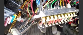
Relay and fuse diagram for VAZ 2110
The mounting block, in which the main fuses and relays are located, is in the cabin. Its location is to the left of the driver, below the dashboard, like other cars from this manufacturer. Relays are traditionally designated on the diagram by the letter K, and fuses by F. There are 8 fuse elements in the main block:
| Relay no. | Purpose |
| K1 | Lamp condition |
| K2 | Front glass cleaner |
| K3 | Relay-breaker for direction indicators and hazard warning lights |
| K4 | Low beam |
| K5 | Turning on the high beams |
| K6 | Additional starter relay |
| K7 | Heated rear window |
| K8 | Rear fog light |
As for fuses, there are 20 of them:
| Fuse no. | Current (amps) | Description of fuses |
| F1 | 5 | License plate lamps. Instrument lighting lamps. Indicator lamp. Trunk light. Left side lamp |
| F2 | 7,5 | Near left headlight |
| F3 | 10 | Far left headlight |
| F4 | 10 | Right fog light |
| F5 | 30 | Door window motors |
| F6 | 15 | Portable lamp or socket |
| F7 | 20 | Engine cooling fan motor. Sound signal |
| F8 | 20 | Heated rear window. Turning on the heated rear window |
| F9 | 20 | Recirculation valve. Windshield and headlight cleaners and washers. Rear window heating coil |
| F10 | 20 | Reserve |
| F11 | 5 | Right side light |
| F12 | 7,5 | Right low beam |
| F13 | 10 | Right high beam. High beam warning lamp |
| F14 | 10 | Left fog light |
| F15 | 20 | Electrically heated seats. Trunk lock lock |
| F16 | 10 | Relay-breaker for direction indicators and hazard warning lights (in hazard warning mode). Hazard warning lamp |
| F17 | 7,5 | Interior lighting. Individual lighting. Illuminated ignition switch. Brake light bulbs. Clock or trip computer |
| F18 | 25 | Glove compartment lighting. Heater controller. Cigarette lighter. |
| F19 | 10 | Locking door locks. Relay for monitoring the health of brake light lamps and side lights. Direction indicators with warning lamps. Reversing light. Generator excitation winding. On-board control system display unit. Instrument cluster. Clock or trip computer |
| F20 | 7,5 | Rear fog light |
Main unit
The main mounting block is located near the driver's seat on the front panel, to the left of it. The niche is closed by a plastic lid with a shutter above it in the shape of a button - to open it you need to press it. Under the cover there are fuses, numbered in the diagram from F1 to F20 - they are responsible for all vehicle control elements, except for those placed in an additional block (there are three of them). The power of the fuses is different. There are also eight relays responsible for the main elements of the car control power circuit.
Console additional mounting block
You can find it inside the center console. It is located behind a plastic cover attached with screws, to the left of the front passenger seat. The block contains three relays and three fuses. In particular:
- Fan motor relay;
- Ignition relay;
- Fuel pump motor relay;
- Engine ECU and ignition module fuse;
- Fuse for electronic elements of the fuel supply system;
- Fuse for the electrical circuit of the speed and oxygen sensors, as well as the air flow meter and the canister purge valve.
The power of all fuses is rated at 15 Amps.
Mounting block connection diagram
Numbering of plugs in the connecting blocks of the mounting block and the colors of the wires connected to them
In the diagram, the letters indicate the following colors:
- B - white;
- Ch - black;
- F - yellow;
- O - orange;
- G - blue;
- P - pink;
- Z - green;
- C - gray;
- K - brown;
- P - red.
If the letters are together, then wires of two colors must be connected to the plug.
Changes in switching and layout of mounting blocks
The most important innovation in the VAZ 2110 fuse box from old to new models affected the location of the fog lamp fuse. In the first modifications, this device was located behind the block, and not inside it, and was supported by a bundle of wires, without being equipped with a board. Over time, the designers provided a special board for it, which was still located outside the main unit, but was placed to the left of the console. Only ten years later did it find a place among the other fuses.
Blocks with different layouts differ in numbering. The first models with 6 relays have the number 2110-3722010, while those equipped with 7 devices were marked 2110-3722010-08, and the most modern ones - 2110-3722010-01. Modifications that do not have relay legs for turning on the front lighting are marked as 21110-3722010-12. Also, the manufacturer produces units equipped with legs, but not relay K1, which can be either with or without jumpers - in both cases, independent installation of the device or jumpers instead of it is allowed.
Table of circuits protected by fuses on the VAZ 2110
The table shows all the circuits located in the main mounting block.
Preparing for the test
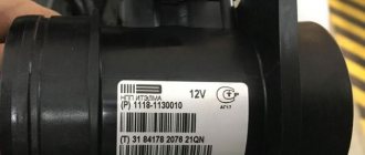
Before you check the relay for functionality with a multimeter, you need to understand what needs to be checked. To do this, you should use a datasheet.
They are looked for by the markings on the body. Just type the value into a search engine and you will find the required document.
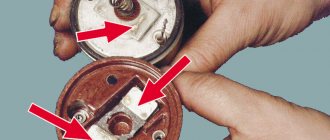
Sometimes the relay diagram is printed directly on the body, which is more convenient. In this case, you won’t need to Google anything.
The contacts in the diagram are shown as dots connected to the winding. Switches are marked with dotted markers.
How to check a solid-state relay with a multimeter if there are no datasheets or circuit diagrams? You will have to visually determine the necessary contacts:
- Inspection. Usually the control contacts are a little lighter than the others; this marker can be used to guide you. In the diagram the contacts look like this.
- Studying the board. If the relay is soldered in, then you can find the supply tracks on the PCB. In addition, the manufacturer often signs the contacts.
- Search for board diagram. Another option is to look for this board with components included. In block diagrams, components can be labeled.
What is a relay and how to determine its contacts is clear, all that remains is to prepare a multimeter. The only thing you need to do is check the battery.
It must be well charged, otherwise the tester will “start lying.”
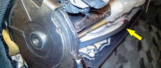
Where is the main relay of the VAZ 2110
Unlike most other relays, the main one is located not in the main one, but in an additional mounting block. The latter is in the cabin, but on the right side of the dashboard, and its cover is secured with 2 screws. This block has 6 elements, 3 of which are fuses and 3 are relays.
| Circuit breakers | Which electrical circuit are they responsible for? |
| 1 | Ignition module |
| 2 | Canister purge valve. Speed sensor. Heating sensor. Air flow sensor |
| 3 | Fuel pump and its relay. Injectors. |
Additional relays include:
| Relay | Purpose |
| 4 | Electric fan |
| 5 | Gasoline pump |
| 6 | Main ignition relay |
Winding diagnostics
Always before checking the fuel pump relay or any other relay for an open circuit, you need to find out the resistance of the coil. Often this information is written on the case or you can find a datasheet. If there is nothing, just focus on the range from tens to hundreds of ohms.
So let's get started:
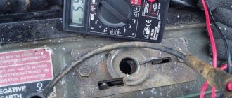
- First you need to set the resistance mode. It is denoted by this symbol Ω. Just set the switch to this position.
- Install the red probe into the socket marked VΩmA. Black – COM, at the very bottom.
- Touch the control contacts with the probes - numbers will appear on the screen (or the arrow will move). If they are within the acceptable range, everything is normal and the coil is working properly.
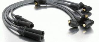
Please note that the coil may be protected by a diode.
For example, windshield wiper relays in a car often come with it. This component may show different values depending on the polarity. Therefore, to be on the safe side, swap the probes after the first measurement.
What are the fuses on the VAZ-2110 responsible for?
In total, there are 20 fuses in the main block, indicated in the diagram by letters and numbers from F1 to F20. Their denominations differ from each other:
| Fuse | Rating, Ampere | What is he responsible for? |
| F1 | 5 | Dashboard lighting and trunk lighting |
| F2 | 7,5 | Left low beam |
| F3 | 10 | Left high beam |
| F4 | 10 | Front right fog light |
| F5 | 30 | Window lifters on doors |
| F6 | 15 | Cigarette lighter and portable lamp |
| F7 | 20 | Sounds and fan |
| F8 | 20 | Heated rear glass |
| F9 | 20 | Front window washer/cleaner |
| F10 | 20 | Reserve |
| F11 | 5 | Right front side light |
| F12 | 7,5 | Right low beam |
| F13 | 10 | Right high beam |
| F14 | 10 | Left fog light |
| F15 | 20 | Heated seats |
| F16 | 10 | Hazard signal, turning lights |
| F17 | 7,5 | Interior lighting and ignition switch lighting |
| F18 | 25 | Interior heating and glove compartment lighting |
| F19 | 10 | Monitoring the serviceability of the brake light and reversing light |
| F20 | 7,5 | Rear fog light |
As for the fuses for the ignition and generator circuits, the battery and everything related to the operation of the engine, they are located in an additional block.
Power supply
The main and auxiliary relays make clicks during operation - this indicates its full functionality. The power couple is responsible for this, which also needs to be checked.
One of the contacts is always energized, while the second receives electricity only when it is on.
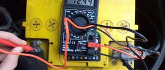
You can check them using a voltmeter. It is also included in the tester and is designated by the symbol “V”. Set the switch to constant voltage mode.
Now you can proceed to checking:
- All components that receive current from the relay must be disconnected.
- Now find the necessary contact to which current always flows. You can find it through the datasheet.
- Place the right probe on it, and short-circuit the second one to the car body.
If there is voltage, everything is fine and there are no problems. If there is no contact, you will have to change the entire relay, since the part is not repairable.