02/09/2021 5,933 VAZ 2108
Author: Ivan Baranov
The Hall sensor of the VAZ 2108 is one of the important components that ensures the normal operation of the power unit. The purpose of this component is to transmit control signals to the switch, which converts these signals and supplies them to the ignition coil. We will tell you in more detail about malfunctions, as well as replacing the device, in this article.
[Hide]
The principle of operation of the sensor and its features
In its operation, the sensor uses the physical Hall effect, discovered in the 19th century. However, they began to use it only in the 70-80s of the last century, when automakers began to switch from contact ignition systems to electronic ones.
The principle of operation of the sensor is quite simple. As the motor shaft rotates, metal blades pass through slots in the motor housing. It gives an electrical impulse to the switch, as a result of which the latter unlocks the transistor and supplies voltage to the ignition coil. It, in turn, converts the low-voltage signal into a high-voltage one and supplies it to the spark plug.
Structurally, the sensor has three contacts:
- for connection to “ground” (car body);
- to connect voltage with a “+” sign and a value of about 6 V;
- to supply a pulse signal from it to the switch.
The advantages of using a Hall sensor in electronic ignition systems are two main factors - the absence of a contact group (which constantly burns out), as well as a higher voltage on the spark plug (30 kV versus 15 kV).
Since Hall sensors are also used in braking and anti-lock braking systems and tachometer operation, the device performs the following additional functions for the car:
- increases engine performance;
- speeds up the functioning of all machine systems.
As a result, the ease of use of the car, as well as its safety, increases.
Signs of a Hall sensor malfunction
Sensor failures manifest themselves in different ways . Identifying them can sometimes be difficult even for an experienced master. Here are some of the most common symptoms and problems with the Hall sensor:
- starts poorly or does not start at all;
- occurrence of interruptions in engine operation at idle speed;
- “jerking” of the car when driving at high speeds;
- The engine stalls while the car is moving.
If your machine has one or more of these symptoms, it is imperative to check the sensor.
About the hall sensor in detail
ATTENTION! A completely simple way to reduce fuel consumption has been found! Don't believe me? An auto mechanic with 15 years of experience also didn’t believe it until he tried it. And now he saves 35,000 rubles a year on gasoline! Read more"
DCs are available in various modern automotive systems. Elements have been created to communicate important information to the ECM (electrical control system of the internal combustion engine). The latter concerns any changes occurring in the operation of the motor. The ignition system is no exception - and it is equipped with its own sensor, which takes on the task of monitoring normal functioning.
Speaking in purely scientific language, the DH is designed to calculate the angle of position of the motor shafts.
Interesting point. On modern high-class cars such as Audi, BMW or Volkswagen, the DH performs much more functions. But old-type car models equipped with a contact system imply a DC as an integral element of the distributor.
Even on domestic models, such as GAZ 24, “eight”, “nine”, etc., DH is installed, and the ignition system is modernized.
The DC operates on the principle of the voltage increasing effect. In other words, it is a very sensitive element that instantly responds to impulses. In this case we are talking about magnetic field pulses affecting the conductor. As soon as the car's ignition is turned on, the electromotive force in the ignition system changes, which forces the DC to use the switch and spark plugs (SZ).
The DC detects pulses that appear after a change in the magnetic field. The latter occurs during the rotation of the camshaft. However, for the sensor to be activated, a specific value of magnetic induction is needed.
To more fully understand the operating principle of DH, you need to imagine the following:
- a crown plate with slots (the number of slots determines the number of cylinders of the internal combustion engine) on the distributor drive;
- permanent magnet on the camshaft sensor.
How to check the Hall sensor
There are several verification methods . Briefly, they work like this:
Checking the serviceability of the hall sensor (diagram)
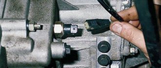
- Creating a simulation of the presence of a Hall sensor . This method of checking is the fastest and is suitable if there is power at the ignition system components, but there is no spark. For this purpose, the three-pin block is removed from the distributor. Next, you need to turn on the car’s ignition and connect (short with a piece of wire) outputs 3 and 2 (negative pin and signal contact). If during this process a spark appears , it means the sensor has failed . Please note that in order to detect sparking, you need to hold the high-voltage wire near ground.
- Checking the Hall sensor with a multimeter is the most common method. For this check, a multimeter (tester) is used. To do this, it is enough to measure the voltage at the output of the sensor. If it is working properly, then the voltage should be within 0.4. 11 V.
- Replacing a faulty device with a known working one . You can borrow it from friends who have a car with the same sensor. If after replacement the problems that bother you disappear, you will have to buy and replace the Hall sensor with a new one.
Hall sensor check
Hall sensor, checked with a multimeter.
Another common method is to check for resistance at the sensor . To do this, you need to make a simple device consisting of a 1 kOhm resistor, an LED and flexible wires. A resistance is soldered to the LED leg, and two wires of a length that is convenient for operation (not short) are soldered to it.
Then remove the distributor cover, disconnect the distributor and plug box. Next, check the serviceability of the electrical circuit. To do this, an electronic multimeter (voltmeter) is connected to terminals 1 and 3, after which the car’s ignition is turned on. obtained on the screen of the measuring device should be within 10.12 V.
Next, we similarly connect the constructed device to the same terminals. If you guessed the polarity correctly, the LED lights up. Otherwise, the wires must be swapped. The further procedure is as follows:
- do not touch the wire connected to the first terminal;
- We transfer the end from the third terminal to the free second;
- rotate the camshaft (manually or using a starter).
If the LED blinks while the shaft is turning, then everything is in order and the Hall sensor does not need to be replaced.
It is worth noting that the process of checking the Hall sensor on the VAZ 2109, Audi 80, Volkswagen Passat B3 and other cars is carried out according to the same scheme. The only difference is the location of individual parts under the hood of the car.
Checking the sensor with a multimeter
You can check the DH in different ways. One popular diagnostic option is a multimeter or voltmeter. This verification method has two options. Let's look at how to check a car's hall sensor in both cases.
1st method
To carry out diagnostics, you need to find a working voltmeter or multimeter that is set to measure DC voltage (direct current) in the range of 20 Volts. In addition, you will need to stock up on 2 iron pins, through which the DC will be checked. Before checking the hall sensor, you will need to remove the rubber boot from the block, which is connected to the distributor and directly to the DH.
Let's continue:
- remove the main armored wire from the distributor;
- We connect it to the arrester or to ground.
This is done in order to exclude the accidental occurrence of a discharge, because this may contribute to starting the engine during the test.
Checking the digital Hall sensor.
Further:
- turn on the ignition;
- remove the block from the distributor;
- set the mode on the multimeter to DC 20 V;
- We connect the negative terminal of the device to ground (any part of the car body);
- the positive probe of the device will serve as a voltage meter.
The block going to the distributor has three wires: red, green and white (colors may be different). On the red wire, the voltage of the device should show 11.37 or close to 12 V. On the green or middle wire, the value is also close to 12 V. And finally, on the last - white wire, the value is 0.
Checking the Hall sensor with a tester.
By the way, if you put the device in the audio test mode, then placing the probe on the contact, you will hear a constant ringing, which will indicate that the white wire is connected to ground. That's how it should be. What did the preliminary check give? We made sure that the households received all the necessary impulses. Continue (multimeter in DC measurement mode):
- We take the prepared pins (studs) and thread them like this: one into the green (middle wire), the other into the white (ground wire);
- We connect the block in its place, in the car distributor.
Why are pins needed? They play the role of a current conductor. There are no contacts on the back of the block, and the values can only be checked if the wires are exposed. This is not recommended, which is why the pins are inserted. Go ahead:
- take the multimeter clamps (ignition is on);
- We connect the positive terminal of the multimeter to the pin of the middle wire of the block, and the negative terminal to the other (white wire).
It will be interesting➡ Checking the LED with a tester
In this position, the multimeter value should be within 11.2 V. Next:
- crank the crankshaft while simultaneously observing the instrument readings;
- if the instrument readings drop to 0.02 V (lower measurement limit) and rise to 11.8 V (upper measurement limit) when cranking the crankshaft, then this is considered normal.
Attention. The DC is considered to be in good working order if, when cranking the crankshaft, the upper measurement limit is no less than 9 V, and the lower limit is no more than 0.4 V. Thanks to these measurements, we checked the performance of the DC installed in the car distributor.
Material on the topic: how to determine current power.
2nd method
The second verification method differs from the first in that this time the DH is diagnosed autonomously. In other words, it will not be connected to the ignition system - to the switch. So, to carry out this method you will need a homemade assembly of 3 contacts inserted into the distributor block, plus/minus pins and 2 test points for measurements. The homemade assembly diagram will look like this
Here's what to do:
- Connect the three homemade contacts to the connectors where the original distributor block is inserted (if the sensor is removed, then to its terminals);
- supply plus/minus power to the homemade assembly;
- connect the plus of the multimeter to one control point for measurement, the minus to the other;
- turn the crankshaft.
Again, the upper limit of measurements on a working sensor should not be lower than 9 V, and the lower limit should not be higher than 0.4 V. If the DC is removed from the car, then it will be checked as follows:
- the sensor leads are connected to the homemade assembly (the other connections are the same as in the case described above);
- take a knife or curtain and draw the blade along the slot in the DH.
When the curtain is closed, the DC readings are above 9 V, when open – below 0.4 V. Thus, using a multimeter, you can check the DC for serviceability in 2 simple ways. Of course, there are many other options for checking the sensor, but they are more difficult to carry out, although they provide instant access to the DH. A general familiarity with the operating principle of DCs, despite the gradual displacement of contactless ignition systems by multiprocessor ones, will provide many benefits in the future. So, this can help the car owner when using other car sensors that operate on the Hall principle: speed sensor, camshaft position, etc.
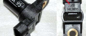
Various models of Hall sensors.
Checking the Hall sensor and replacing it
The Hall sensor is one of the most important elements of the contactless ignition system for gasoline engines. The slightest malfunction of this part leads to serious problems in the operation of the motor. Therefore, in order to avoid diagnostic errors, it is important to know how to check the Hall sensor and, if necessary, to be able to replace it.
We divided this material into two parts: theoretical (purpose, design and principle of operation of the Hall sensor) and practical - signs of malfunction, verification methods and replacement methods.
At the end of the article, watch the video instructions on how to replace the Hall Sensor yourself.
And before checking the Hall sensor for malfunctions, let's understand its purpose and operating principle.
Hall sensor for VAZ 2107
The Hall sensor is one of the main devices in the contactless ignition system of gasoline engines. If a problem occurs with this part, the operation of the engine is disrupted. In order to be able to diagnose the problem in a timely manner, it is important to know and understand how the Hall sensor (HL) works and, in particular, on the VAZ 2107, how to determine the malfunction and replace the device. All these points are worth dwelling on in more detail.
The Hall sensor is the main element of the contactless ignition system of a gasoline engine
Purpose of the sensor
A number of electronic car systems are equipped with sensors that send a signal to the corresponding unit responsible for the operation of the power unit to change certain parameters. The contactless ignition system of the VAZ 2107 also has a device called a Hall sensor (HL). Its purpose is to determine the position angle of the crankshaft and camshaft of the power unit. The sensor is installed not only on modern, but also on old cars, for example, VAZ 2108/09. According to the readings of the element, current is supplied to the spark plugs.
Operating principle of the device
The operation of a DC is based on the effect of increasing voltage in the cross section of a conductor placed in a magnetic field. At the moment when a spark should appear, a change in the electromotive force occurs; a signal from the distributor is sent to the switch and spark plugs. If we consider the Hall sensor, which is used today in contactless ignition systems, it is a device for detecting changes in the magnetic field during camshaft operation. To trigger the element, a certain value of magnetic induction is required.
The sensor works as follows: there is a special crown-type plate on the distributor axis. Its special feature is the slots, the number of which corresponds to the number of engine cylinders. The sensor design also includes a permanent magnet. As soon as the ignition distributor shaft begins to rotate, the driven plate intersects with the sensor space, which leads to the generation of a pulse that is transmitted to the ignition coil. This impulse is converted and causes a spark to form on the spark plugs, as a result of which the air-fuel mixture is ignited.
The principle of operation of the Hall element: 1 - magnet; 2 - plate of semiconductor material
As the engine speed increases, the frequency of pulses coming from the DC increases, which determines the normal operation of the power unit. Despite the fact that the phenomenon considered was discovered long before production cars appeared, it is nevertheless used in automotive production today. The sensor is a fairly reliable device, the breakdown of which does not occur very often.
Video: Hall sensor operation
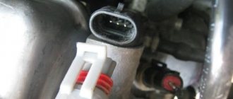
The Hall sensor has three contacts:
- weight;
- plus power (about 6 V);
- communication with the ignition system switch.
Where is the DH on the VAZ 2107
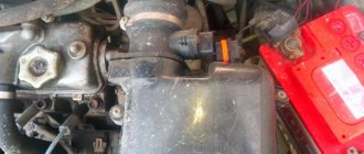
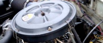
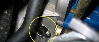
If you are the owner of a VAZ “Seven” with contactless ignition, then it will not be superfluous to know where the Hall sensor is located. Finding the ignition distributor is not difficult, but the sensor itself is located under its cover. To access the DC, you need to remove two latches and remove the distributor cover, after which you can see the sensor itself.
The Hall sensor on the VAZ 2107 is located in the engine compartment under the distributor cover
Connection diagram
The Hall sensor has a direct connection with the switch and is connected according to the diagram shown in the figure.
The Hall sensor has a simple connection diagram: the signal from the device is supplied to the switch, and then to the ignition coil
The switch itself performs the following functions:
- amplifies the pulses to 12 V and transmits them to the ignition coil;
- receives a signal from the DC in the form of an impulse.
In simple words, the switch is a regular amplifier, which is designed in a similar way to an assembly based on field-effect transistors. Despite the simplicity of the circuit, the device is easier to purchase than to make yourself. The main thing is that the Hall sensor and the switch on the VAZ 2107 are correctly installed and connected. Otherwise, the sensor will not work properly.
The switch is designed to amplify the pulses received by it from the Hall sensor
What is a Hall sensor and how does it work
The Hall sensor (also known as a camshaft position sensor) is one of the main elements of the distributor. It is located next to the distributor shaft, on which a magnetically conductive plate, similar to a crown, is attached. There are as many slots in the plate as there are cylinders in the engine. There is also a permanent magnet inside the sensor.
The principle of operation of the Hall sensor is as follows: when the shaft rotates, metal blades alternately pass through a slot in the sensor. As a result, a pulse voltage is generated, which enters the ignition coil through the switch and, converted into high voltage, is supplied to the spark plugs.
The Hall sensor has three terminals:
- one connects to the “mass”,
- the second is approached by a plus with a voltage of about 6 V,
- The converted pulse signal goes from the third terminal to the switch.
How voltage occurs on the Hall sensor
How is everything going? Let's try to figure it out.
Another name for the Hall sensor is the phase sensor or camshaft sensor. It determines the angular position of the shaft at a given moment. As it rotates, metal blades pass through the holes on the sensor. The resulting control pulse is transmitted to the switch, which converts them into current pulses on the ignition coil. There is a gradual increase in current strength in the coil winding as the pulse passes from the sensor. The coil induces a high voltage pulse. The sensor directs it to the spark plug, thereby facilitating the correct selection of the moment of sparking.
The Hall sensor transmits cylinder block recognition data so that only one cylinder is injected. That is, it is designed to regulate injection.
Now everything is the same, in understandable language:
- It is implanted into the ignition system (that is, a conductor is placed in the magnetic influence zone)
- As soon as a spark is formed, a voltage is generated on our device, the magnitude of which ultimately depends on the angle of deflection of the knees and camshafts.
- From here, a pulse with a changed voltage value is transmitted to the switch
- Pulses with changed voltage are read by the ECU
- After processing and calculating the parameters of optimal operation, signals from the ECU are sent to the appropriate authorities.
The sensor is an integral part of the distributor and is installed next to the camshaft. The design of the device includes a magnetic base and a plate on which there are slots according to the number of cylinders in the engine.
When connecting, three terminals are used - ground, output voltage, voltage to the switch
The Hall sensor connection diagram is unique in that simply inserting it into the ignition circuit does not disrupt its operation. This is what makes this device indispensable for solving the problem of recognizing the position of shafts.
Signs of a Hall sensor malfunction
Hall sensor malfunctions manifest themselves in different ways. Even an experienced technician will not always immediately identify the cause of engine problems.
Here are some of the most common symptoms:
- The engine starts poorly or does not start at all.
- At idle, the engine runs rough and jerky.
- The car may jerk when driving at high speeds.
- The power unit stalls while driving.
If one of these signs appears, you must first check the serviceability of the Hall sensor.
Also, do not exclude other malfunctions of the ignition system found in cars.
Hall sensor failure
To recognize the breakdown of this particular device, you need to know several symptoms of this scourge:
- The engine "guzzles" gasoline
- Rough engine operation. The car jerks, there is a loss of speed, the engine stalls
- The gearbox does not change gears. Restarting the engine solves the problem. However, its repeated occurrence indicates a failure of the Hall sensor
- Spark plugs do not spark, even when changing the entire set
- Incorrect self-diagnosis
- The “check” on the panel lights up chaotically at idle and goes out only at high speeds
The reason for this behavior of the machine and the occurrence of the above problems is not always a breakdown of the sensor. These may be faulty wiring or related components. For example:
- no connection to signal wires
— moisture getting on the contacts
— breaks, short circuits, incorrect connection of various parts of the electrical circuit
— malfunction: ECU, ignition circuits
— mechanical damage to the camshaft gears
How to check the Hall sensor
A simple way to check the camshaft position (Hall) sensor is shown in the following video.
There are several ways to check the health of the Hall sensor. Each motorist can choose the most suitable option for himself:
- Take a working sensor from a neighbor or at a car disassembly for testing and install it instead of the “native” one. If the engine problems disappear, then you will have to buy a new part.
- Using a tester, you can measure the voltage at the sensor output. In a working device, the voltage will vary from 0.4 V to 11 V.
- You can create a simulation of a Hall sensor. To do this, remove the three-pin block from the distributor. Then turn on the ignition and connect outputs 3 and 6 of the switch with a piece of wire. The appearance of a spark indicates that the sensor has failed.
If the test reveals that the Hall sensor is faulty, then it must be replaced with a new one.
Hall sensor replacement
Replacing the Hall sensor will not be particularly difficult. Even a novice car enthusiast can handle this work with his own hands.
The video below shows in some detail the process of replacing the sensor in the distributor of a UAZ car.
Typically, replacing a Hall sensor consists of several steps:
- First of all, the distributor is removed from the car.
- Next, remove the distributor cover and align the timing mechanism mark with the crankshaft mark.
- Having remembered the position of the distributor, you need to unscrew the fasteners with a wrench.
- If there are latches and stoppers, they should also be removed.
- The shaft is pulled out of the distributor.
- All that remains is to disconnect the terminals of the Hall sensor and unscrew it.
- By pulling back the regulator, the faulty part is carefully removed through the gap formed.
- The new Hall sensor is installed in the reverse order.
The history of the Hall sensor
Electronic control of the functions of all parts and processes in the car is possible exclusively thanks to built-in sensors. They continuously inform the central control body about all changes, including any failures in the coordinated operation of systems.
The Hall sensor is one of these ECU agents that is responsible for the throttle valve positions. It transmits changing parameters of the magnetic field. The effect of the appearance of a potential difference and, as a consequence, voltage, when a direct current conductor is placed in a magnetic field - the operation of this device is based on this idea. This phenomenon was discovered and studied by Edwin Hall and is named after him. Hence the name of our sensor.
Hall sensors: operating principle, types, application, how to check
An electromagnetic device called a Hall sensor (hereinafter referred to as Hall sensor) is used in many devices and mechanisms. But its greatest application was found in the automotive industry. In almost all models of the domestic automobile industry (VAZ 2106, 2107, 2108, etc.), the non-contact ignition system for a gasoline engine is controlled by this sensor. Accordingly, when it fails, serious problems arise with the operation of the engine. In order not to make mistakes when diagnosing, it is necessary to understand the principle of operation of the sensor, know its design and testing methods.
Hall sensor voltage
Engines with fuel injection systems have become widespread. The development and implementation of injectors was dictated by the realities of the modern world. There were more and more cars, emissions into the atmosphere exceeded all permissible standards. The issue of quality control of vehicle exhaust gases became acute, and this is how the Hall sensor appeared. An injector is one of the effective ways to reduce emissions into the planet’s atmosphere. In addition, it helps to increase the efficiency of the internal combustion engine, hence the performance of the entire vehicle.
- 1 History of the Hall sensor
- 2 How voltage occurs on the Hall sensor
- 3 Failure of the Hall sensor
- 4 Testing and replacing the Hall sensor
Briefly about the principle of operation
The principle of operation of the ignition sensor is based on the Hall effect, which received its name in honor of the American physicist who discovered this phenomenon in 1879. By applying a constant voltage to the edges of a rectangular plate (A and B in Fig. 1) and placing it in a magnetic field, Edwin Hall discovered a potential difference at the other two edges (C and D).
Fig.1. Demonstration of the Hall effect
In accordance with the laws of electrodynamics, the Lorentz force acts on charge carriers, which leads to a potential difference. The Hall voltage value is quite small, ranging from 10 µV to 100 mV, it depends on both the current strength and the electromagnetic field strength.
Until the middle of the last century, the discovery did not find serious technical application until the production of semiconductor elements based on silicon, ultra-pure germanium, indium arsenide, etc., with the necessary properties, was established. This has opened up opportunities for the production of small-sized sensors that can measure both field strength and current flowing through a conductor.
Types and scope of application
Despite the variety of elements that use the Hall effect, they can be divided into two types:
- Analogue, using the principle of converting magnetic induction into voltage. That is, the polarity and voltage directly depend on the characteristics of the magnetic field. Currently, this type of devices is mainly used in measuring technology (for example, as current, vibration, rotation angle sensors).
Hall effect current sensors can measure both AC and DC current - Digital. Unlike the previous type, the sensor has only two stable positions, indicating the presence or absence of a magnetic field. That is, operation occurs when the intensity of the magnetic field has reached a certain value. It is this type of device that is used in automotive technology as a sensor for speed, phase, camshaft position, as well as crankshaft, etc.
It should be noted that the digital type includes the following subtypes:
- unipolar - triggering occurs at a certain field strength, and after it decreases, the sensor returns to its original state;
- bipolar - this type reacts to the polarity of the magnetic field, that is, one pole turns the device on, and the opposite pole turns it off.
Appearance of a digital Hall sensor
As a rule, most sensors are a component with three pins, two of which are supplied with bi- or single-pole power, and the third is a signal one.
Example of using an analog element
Let us consider, as an example, the design of a current sensor whose operation is based on the Hall effect.
Simplified circuit of a current sensor based on the Hall effect
Designations:
- A is a conductor.
- B – open magnetic conductor ring.
- C – analog Hall sensor.
- D – signal amplifier.
The operating principle of such a device is quite simple: the current passing through the conductor creates an electromagnetic field, the sensor measures its magnitude and polarity and produces a proportional voltage UDT, which is supplied to the amplifier and then to the indicator. https://www.youtube.com/watch?v=fmLs9WsKx3I
Purpose of DC in the car ignition system
Having understood the principle of operation of the Hall element, let's consider how this sensor is used in the contactless ignition system of the VAZ line of cars. To do this, let's look at Figure 5.
Rice. 5. Principle of the SBZ device
Designations:
- A – sensor.
- B – magnet.
- C – plate made of magnetically conductive material (the number of protrusions corresponds to the number of cylinders).
The operating algorithm of such a scheme is as follows:
- When the chopper-distributor shaft rotates (moving synchronously with the crankshaft), one of the protrusions of the magnetically conductive plate takes a position between the sensor and the magnet.
- As a result of this action, the magnetic field strength changes, which causes the DC to operate. It sends an electrical impulse to the switch that controls the ignition coil.
- The voltage required to form a spark is generated in the Coil.
Manifestation of malfunction and possible causes
Irregularities in the operation of household farms can be detected by the following indirect signs:
- There is a sharp increase in fuel consumption. This is due to the fact that the fuel-air mixture is injected more than once during one crankshaft rotation cycle.
- Manifestation of unstable engine operation. The car may begin to “twitch” and a sharp deceleration occurs. In some cases, it is not possible to reach a speed of more than 50-60 km/h. The engine stalls during operation.
- Sometimes the failure of the sensor can lead to the transmission being locked, without the ability to shift it (in some models of imported cars). To correct the situation, a restart of the engine is required. In case of regular such cases, one can confidently state that the DP has failed.
- Often, a breakdown can manifest itself in the form of the disappearance of the ignition spark, which, accordingly, will make it impossible to start the engine.
- The self-diagnosis system may experience regular failures, for example, the check engine light will come on when it is idling, and the light will go out when the speed increases.
It is not at all necessary that the listed factors are caused by the failure of the DP. There is a high probability that the malfunction is caused by other reasons, namely:
- ingress of debris or other foreign objects onto the DP housing;
- the signal wire has broken;
- water has entered the DP connector;
- the signal wire is shorted to ground or the on-board network;
- the shielding sheath on the entire harness or individual wires is torn;
- damage to the wires supplying power to the DC;
- the polarity of the voltage supplied to the sensor is reversed;
- problems with the high-voltage circuit of the ignition system;
- problems with the control unit;
- the gap between the DC and the magnetic conductive plate is incorrectly set;
- Perhaps the reason lies in the high amplitude of the end runout of the camshaft gear.