04/10/2021 3,009 Sensors
Author: Ivan Baranov
The braking system of modern cars is equipped with an anti-lock braking system, which reduces the braking distance and allows you to drive the car in a sharp deceleration mode. To check the ABS sensor, you can use a tester, an oscilloscope, or perform diagnostics without instruments.
[Hide]
Methods for checking the ABS sensor
ABS sensors play an important role in the operation of the car's braking system - the braking efficiency and uninterrupted operation of the unit as a whole depend on them. The sensor elements send data about the degree of rotation of the wheels to the control unit, and it analyzes the incoming information, building the desired algorithm of actions. But what to do if you have doubts about the serviceability of the devices?
- 1 Symptoms of device malfunction
- 2 Methods for checking functionality 2.1 Using a tester (multimeter) 2.1.1 Video “Diagnostics of the ABS sensor”
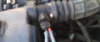
Inductive type element design
Since inductive sensors are the most common, their design will be considered in the future.
Such a sensor consists of an inductive coil, inside of which a magnetic core is placed. It is installed next to the toothed impulse ring, but so that there is a certain gap between them.
When the wheel rotates, the ring teeth pass through the magnetic field created by the core, which affects the magnetic flux, causing the alternating voltage value in the coil winding to change.
As a result, the speed of rotation of the wheel, and with it the pulse ring, affects the frequency and amplitude of oscillations of the output voltage on the coil. These parameters are fed to the “brains”, as a result of which they estimate the speed of deceleration of the wheel.
Problems with at least one of the ABS sensors can lead to a complete shutdown of the system. And although the braking system on the car will work, you can forget about the braking efficiency and safety that ABS provided.
Symptoms of a device malfunction
The fact that the ABS sensor is faulty will be indicated by an indicator on the instrument panel - it lights up when the system is deactivated, which turns off even if there is the slightest problem.
Evidence that ABS has stopped “interfering” with the operation of the brakes:
- Wheels constantly lock during heavy braking.
- There is no characteristic knocking noise with simultaneous vibration when pressing the brake pedal.
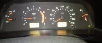
- The speedometer needle is delayed relative to acceleration or does not move from its original position at all.
- If two (or more) sensors on the dashboard are faulty, the parking brake indicator also lights up and does not go out.
Methods for checking the ABS sensor The ABS indicator on the dashboard indicates a system malfunction
What to do if the ABS warning lamp on the car’s dashboard does not behave quite correctly? You should not immediately change the sensor; first, the devices should be checked - this procedure can be performed independently, without resorting to the services of highly paid craftsmen.
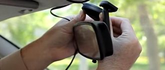
Using an Auto Scanner
For those who are accustomed to troubleshooting car problems with their own hands, the ELM327 auto scanner will be an indispensable assistant when repairing ABS. We have already introduced our readers to this useful gadget. Today it can be purchased at prices ranging from 350 to 1100 rubles. Let us remind you that this miniature device is inserted into a special OBDII diagnostic connector, which many modern cars are equipped with today. Depending on the design features of a particular model, it transmits information about various parameters and errors detected in the vehicle to a smartphone or tablet (via Bluetooth, Wi-Fi or USB). Checking the entire ABS system and finding a faulty sensor using such a device takes a few minutes.
Ways to check functionality
To determine the condition of a part, we will perform a series of steps to diagnose it, moving from simple to complex:
- Let's check the fuses by opening the unit (inside the passenger compartment or in the engine compartment) and inspecting the corresponding elements (indicated in the repair/operation instructions). If a burnt component is found, we will replace it with a new one.
- Let's inspect and check:
- integrity of connectors;
- wiring for abrasions that increase the risk of a short circuit;
- contamination of the part, possible external mechanical damage;
- fixation and connection to ground of the sensor itself.
If the listed measures do not help to identify a device malfunction, it will have to be checked using instruments - a tester (multimeter) or an oscilloscope.
Tester (multimeter)
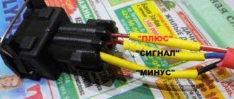
This method of diagnosing the sensor will require a tester (multimeter), instructions for operating and repairing the car, as well as PIN - wiring with special connectors.
Methods for checking the ABS sensor The device combines the functions of an ohmmeter, ammeter and voltmeter
Tester (multimeter) is a device for measuring electric current parameters, combining the functions of a voltmeter, ammeter and ohmmeter. There are analog and digital device models.
To obtain complete information about the performance of the ABS sensor, you need to measure the resistance in the device circuit:
- We lift the car with a jack or hang it on a lift.
- Remove the wheel if it prevents access to the device.
- Remove the cover of the system control unit and disconnect the controller connectors.
- We connect the PIN to the multimeter and the contact socket of the sensor (the connectors for the rear wheel sensors are located inside the cabin, under the seats). Methods for checking the ABS sensor Connect the PIN to the tester and the sensor contact socket
- We measure the resistance (tester in ohmmeter mode) at the contacts of the device. We compare the readings of the device with the car’s operating manual, where the required parameters should be indicated.
- We check the electrical circuit by ringing the sensor wiring for a possible short circuit.
- We spin the wheel manually and at the same time measure the resistance - the tester readings should change depending on the rotation speed.
- We switch the tester to the “voltmeter” mode and measure the voltage on the sensor - we turn the wheel at a frequency of 1 rev/sec, monitoring the readings of the device. Voltage parameters from 0.25 to 1.2 V are considered optimal, but it should be taken into account that increasing the wheel speed necessarily increases them.
The device readings must correspond to the data specified in the repair and operation manual for a particular vehicle. If the device resistance:
- below the minimum threshold - the sensor is faulty;
- approaches zero - short circuit;
- unstable (jumping) at the moment of twitching of the wire - a violation of contact inside the wiring;
- infinity or no readings - wire break.
Attention! The resistance of the ABS sensors on the front and rear axles is different. The operating parameters of the devices are 1–1.3 kOhm in the first case and 1.8–2.3 kOhm in the second.
Video “Diagnostics of the ABS sensor”
How to check using an oscilloscope (with connection diagram)
In addition to self-diagnosis of the sensor with a tester (multimeter), it can be checked using a more complex device - an oscilloscope.
Methods for checking the ABS sensor The device examines the amplitude and time parameters of the sensor signal
An oscilloscope is a device that studies the amplitude and time parameters of a signal, which is intended for accurate diagnosis of pulse processes in electronic circuits. This device detects problems with connectors, broken connections to ground, and broken conductors. The test is performed by visually observing the vibrations on the device display.
To diagnose the ABS sensor with an oscilloscope, you must:
- Fully charge the battery so that during the measurement you can observe voltage drops (jumps) on the connectors or conductors.
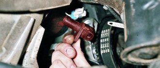
- Find the touch sensor and disconnect the upper connector of the part.
- Connect an oscilloscope to the contact socket. Methods for checking the ABS sensor Connecting the device to the ABS sensor connector (1 - toothed disc-rotor; 2 - sensor)
- Rotate the suspended wheel (by lifting the car on a jack or lift) at a constant frequency of 2-3 revolutions per second.
- Detect the amplitude of signal oscillations on the device display.
- Rotate the second wheel of the axle and similarly detect vibrations.
The serviceability of the ABS sensor is indicated by:
- equal amplitude of signal fluctuations when the wheels of one axle rotate;
- absence of amplitude beats when diagnosing with a sinusoid signal of lower frequency;
- maintaining a stable, even amplitude of signal fluctuations not exceeding 0.5 V when the wheel rotates at a frequency of 2 rps.
Note that an oscilloscope is a rather complex and expensive device. Modern computer technologies make it possible to replace this device with a special program downloaded from the Internet and installed on a regular laptop.
Video “Laptop instead of an oscilloscope”
Checking a part without instruments
The easiest way to diagnose a device without instruments is to check the magnetic valve on the induction sensor. Any metal product (screwdriver, wrench) is applied to the part inside which the magnet is installed. If the sensor does not attract it, it is faulty.
Most anti-lock brake systems of modern cars have a self-diagnosis function with errors displayed (in alphanumeric encoding) on the on-board computer screen. You can decipher these symbols using the Internet or the machine’s operating instructions.
Types of sensors
There are three types of such elements, differing in their operating principle. The most common passive sensors are induction type.
The essence of their work comes down to a change in voltage due to the influence of a magnetic field. Their main disadvantage is the inability to determine the speed of rotation of the wheel at very low speeds.
The remaining two types are active.
One of them is magnetoresistive (rare). The principle of its operation is based on the magnetoresistive effect - the property of a semiconductor to change the trajectory of electrons when exposed to a magnetic field.
The second type of active sensor uses the Hall effect, in which electrons on a semiconductor wafer move to its edges when the magnetic field changes.
How to check the ABS sensor yourself
The efficiency of a car's braking system largely depends on the driver's skills and professional abilities. But, in this case, various auxiliary systems and components that make it possible to create all the necessary conditions for safe driving are of significant help.
A special role in this case is played by an electronic mechanism that prevents the wheels from locking - the anti-lock braking system. In fact, the range of action of the presented system goes far beyond its intended purpose, which is best reflected in the controllability of the vehicle in various operating modes.
One of the most important components of this system is the ABS sensor. The effectiveness of the entire braking process depends on its proper operation. Let's get to know him better.
Wiring repair
The damaged section of the wiring can be replaced. For this:
- Disconnect the wire plug from the control unit.
- Draw or photograph a diagram of the location of the wiring fastening brackets with distance measurements.
- Unscrew the fastening bolt and dismantle the sensor with wiring, having previously removed the mounting brackets from it.
- Cut off the damaged section of the wire, taking into account the length available for soldering.
- Remove protective covers and brackets from the cut cable.
- Covers and fastenings are placed on the wire, pre-selected according to its outer diameter and cross-section, using a soap solution.
- Solder the sensor and connecting plug to the ends of the new harness.
- Insulate solder joints. The quality of the insulation determines the accuracy of the signals transmitted by the sensor and the service life of the repaired section of the wiring.
- The sensor is installed in place, the wiring is positioned and secured according to the diagram.
- Check the operation of the system in different speed modes.
The soldering area must be properly insulated to increase the accuracy of the transmitted signals
The safety of road users depends on the effectiveness of the anti-lock braking system. If desired, you can diagnose and repair ABS sensors yourself, without resorting to the services of a car service.
The braking system of modern cars is equipped with an anti-lock braking system, which reduces the braking distance and allows you to drive the car in a sharp deceleration mode. To check the ABS sensor, you can use a tester, an oscilloscope, or perform diagnostics without instruments.
Operating principle of the ABS sensor
Any diagnostic measure will not be effective if the driver does not have an idea of the operating principles of the unit or element of the system being examined. Therefore, before the stage involving surgical intervention in the operation of this device, first of all, you should study the principle of its operation.
What is an ABS sensor?
Let's start with the fact that this simple device can be found on each of the 4 hubs of the car. The solenoid is located in its sealed plastic housing.
Another important element of the sensor is the so-called pulse ring. The inner side of the ring is made in the form of gear cutting. It is mounted on the back of the brake disc and rotates with the car wheel. There is a sensor at the end of the solenoid core.
The fundamental features of the operation of this system are based on reading the electrical signal coming from the throttle directly to the reading device of the control unit. So, as soon as a certain torque is transmitted to the wheel, a magnetic field begins to arise inside the electromagnet, the value of which increases in proportion to the increase in the rotation speed of the pulse ring.
As soon as the rotation of the wheel reaches the minimum number of revolutions, the pulse signal from the presented sensor begins to enter the processor device. The pulse nature of the signal occurs due to the toothed rim of the pulse ring.
The subsequent operation of the valve body of the ABS system depends on the frequency of the signal registered in the receiving device. The executive elements of the hydraulic brake force distributor are solenoids, a hydraulic pump and valve mechanisms.
Depending on the intensity of the signal entering the valve body, valve mechanisms controlled by solenoids come into operation. In the event that a wheel locks, the hydraulic unit, taking into account the corresponding signal, reduces the pressure in this brake circuit.
At this moment, the hydraulic pump comes into operation, pumping the brake fluid back into the GTZ reservoir through the open bypass valve. As soon as the driver reduces the force on the pedal, the bypass valve closes, and the pump, in turn, stops working.
At this moment, the main valve opens and the pressure in this brake circuit returns to normal.
The presented modification of the ABS peripheral element is the most common and is used on most domestic and foreign cars.
Due to the relative simplicity of this design, the system elements are highly resistant to mechanical wear and have good performance.
If a part fails, it is not so expensive to carry out the manipulations described below. It's easier to buy and replace the sensor with a new one.
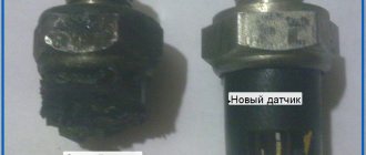
Sensor repair
A failed passive ABS sensor can be repaired yourself. This requires perseverance and mastery of tools. If you doubt your own abilities, it is recommended to replace the faulty sensor with a new one.
Repairs are carried out in the following sequence:
- The sensor is carefully removed from the hub. The soured fastening bolt is unscrewed, having previously been treated with WD40 liquid.
- The protective body of the coil is sawed with a file, being careful not to damage the winding.
- Remove the protective film from the winding with a knife.
- The damaged wire is unwinded from the reel. The ferrite core is shaped like a thread spool.
- For the new winding, you can use copper wire from RES-8 coils. The wire is wound so that it does not protrude beyond the dimensions of the core.
- Measure the resistance of the new coil. It must match the parameter of a working sensor located on the other side of the axis. Reduce the value by unwinding several turns of wire from the spool. To increase the resistance, you will have to re-wind the wire of greater length. Secure the wire with adhesive tape or tape.
- Wires, preferably multi-core, are soldered to the ends of the winding to connect the coil to the harness.
- The coil is placed in the old housing. If it is damaged, then the coil is filled with epoxy resin, having previously positioned it in the center of the housing from the capacitor. It is necessary to fill the entire gap between the coil and the walls of the capacitor with glue so that air voids do not form. After the resin has hardened, the body is removed.
- The sensor mount is fixed with epoxy resin. It is also used to treat cracks and voids that have arisen.
- The body is brought to the required dimensions using a file and sandpaper.
- The repaired sensor is installed in its original place. The gap between the tip and the gear rotor is set to 0.9-1.1 mm using spacers.
After installing the repaired sensor, the ABS system is diagnosed at different speeds. Sometimes the system spontaneously trips before stopping. In this case, the working gap of the sensor is corrected using gaskets or grinding of the core.
It is important! Faulty active speed sensors cannot be repaired and must be replaced with new ones.
Video: how to repair an ABS sensor
Symptoms of a device malfunction
Despite the fact that the presented device is, as a rule, designed for uninterrupted operation over long-term operation, various types of failures and malfunctions may occur during their operation.
To visually monitor the operation of the system, use the emergency lamp on the vehicle's instrument panel. It is he who first of all points to various kinds of system disturbances caused by a number of factors.
A cause for concern in this case may be that the warning light does not go out for a long time after the key is turned to the short-circuit position, or there is no warning while driving.
The problems that caused this behavior of the sensor can be very diverse.
Let's consider a number of signs that will further help identify the cause of the failure of a particular system node:
- The ABS light on the instrument panel stays on for a long time or does not go out at all;
- excessive force when pressing the brake pedal;
- the brake pedal stops responding to its pressing;
- Wheels blocking when the brake pedal is pressed sharply.
ABS systems of earlier versions, as a rule, were not equipped with specialized indication of system operation. In this case, its role was played by the check engine light.
How does ABS work?
With the advent of the new braking system, vehicle safety during emergency braking has increased.
The system began to be installed in the 70s. The ABS system includes a control unit, a hydraulic unit, wheel brakes and speed sensors. The main device of the ABS is the control unit. It is he who receives signals from touch sensors in the form of the number of wheel revolutions and evaluates them. The data obtained is analyzed and the system draws a conclusion about the degree of wheel slip, their deceleration or acceleration. The processed information is sent in the form of signals to the magnetic valves of the hydraulic unit, which performs the control task.
Pressure is supplied from the brake master cylinder (MBC), which ensures the appearance of pressure in the brake caliper cylinders. Thanks to the pressure force, the brake pads are pressed against the brake discs. Regardless of the situation and the force the driver presses the brake pedal, the pressure in the brake system will be optimal. The advantages of the system are that each wheel is analyzed and the optimal pressure is selected, thereby preventing wheel locking. Full braking occurs due to the pressure in the brake drive system, regulated by ABS.
This is the principle of ABS operation. On vehicles with rear-wheel drive and all-wheel drive, there is only one touch sensor, which is located on the rear axle differential. Information about the possibility of blocking is taken from the nearest wheel, and the command about the required pressure is transmitted to all wheels.
The device that controls magnetic valves can operate in three modes:
- With the inlet valve open and the outlet valve closed, the device does not prevent pressure from increasing.
- The inlet valve receives the appropriate signal and remains closed, without changing the pressure.
- The exhaust valve receives a signal that the pressure is decreasing and opens, while the inlet valve closes and the pressure decreases as the check valve turns on.
Thanks to these modes, the pressure decreases and increases in a stepwise system. If problems arise, the ABS system is deactivated and the braking system operates without its participation. On the dashboard, the corresponding indicator indicates problems with ABS.
How to diagnose the ABS system
Diagnostic measures involving checking the ABS system are usually carried out using special equipment. One of them is the so-called diagnostic adapter. To connect it, the manufacturer provides a special diagnostic connector.
The system test begins when the ignition is turned on. The essence of such a check is that using the adapter it is possible to identify the presence of a particular system error. Each error is assigned a specific code, which allows us to judge the malfunction of a specific node or element of the system.
However, it is worth noting that in most cases, budget segment diagnostic adapters do not scan the entire system, but only the engine. Therefore, we recommend using a scanner with comprehensive diagnostics.
For example, we can include a Korean-made model Scan Tool Pro Black Edition . Having a 32-bit chip on board, this scanner is capable of diagnosing not only the engine, but also other components of the car (gearbox, transmission, ABS auxiliary systems, etc.) and at the same time has a fairly affordable price.
This multi-brand scanner is compatible with most cars from 1993 onwards; it shows the operation of all available sensors in real time, the car’s VIN code, its mileage, ECU version, etc.
The device is capable of measuring the stability of various systems over certain periods of time and storing the obtained data in any device based on iOS, Android or Windows.
Diagnostics and preventive measures to judge the performance of system elements are carried out in specialized service centers. However, this task can be handled in a garage environment.
So, all that is required to diagnose the ABS sensor is a minimum set of equipment, including: a soldering iron, a multimeter, heat shrink and repair connectors.
The verification algorithm consists of the following stages:
- wheel jacking;
- dismantling the control unit and controller outputs;
- connecting repair connectors to sensors;
- measuring resistance with a multimeter
Checking the voltage on the sensor winding
Another way to check the performance of ABS sensors is to measure the output voltage that appears on the winding when the wheel rotates. To do this we do the following:
- We hang the wheel using a jack and remove it.
- We find the ABS sensor and disconnect its connector from the wiring leading to the control unit.
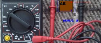
- We switch the multimeter to AC voltage measurement mode.
- We connect the probes to the contacts of the sensor connector.
- Rotate the wheel hub (at a speed of 1÷2 rpm).
- If there is a voltage of 200÷1700 mV (its value varies depending on the specific sensor model), it can be stated that the sensor is working. There's no reason to worry. If you were unable to find the technical specifications of the sensor, it is worth checking all ABS sensors installed on the car in a similar way. If, as a result of testing, a low voltage is detected on one of them (compared to the others), this indicates that it is not operating correctly.
On a note! If, when measuring the resistance of all sensors, the ohmmeter readings indicate their performance, but when the wheel rotates, a low voltage (or absence) appears on the sensor windings, then this may be a consequence of wear or breakage of the gear wheel.
How to resolve detected faults
Once the diagnostic measures are successful and the problem is found, it becomes necessary to eliminate the faulty element of the system. When it comes to the ABS sensor or impulse ring, there is no need to talk about restoring their functionality.
In this case, they usually need to be replaced. An exception may be the case when the working surface of the sensor has simply become dirty during long-term use. To do this, it will be enough to clean it of oxides and dirt particles. It is advisable to use ordinary soapy water as cleaning agents. The use of chemicals is highly undesirable.
If the cause of the failure is the control unit, its resuscitation in some cases can cause serious difficulties. However, you can always open it and, with a visual inspection, assess the scale of the disaster. Dismantling the cover must be done carefully to avoid damage to the working elements.
It often happens that as a result of vibration, the contacts of one of the terminals simply lose their rigidity. To re-solder them to the board you don’t need to have seven spans in your forehead. To do this, it is enough to get a good pulse soldering iron or soldering station.
When soldering, it is important to remember that the ceramic insulator of the block is very sensitive to overheating. Therefore, in this case, care must be taken to ensure that there is no increased thermal impact on it.
Source
Recommendations
To ensure that ABS sensor malfunctions occur as rarely as possible, please contact:
- try to avoid moving in areas with low bushes, so as not to damage the ABS cable;
- sometimes clean the gap between it and the iron comb with a soft brush;
- repair of wheel hubs and suspension arms should be trusted to mechanics who have an understanding of the operation of the ABS system.
A simple circuit for a homemade charger for a car battery, which can help in extreme cases.
How to check the resistance of high-voltage wires with a multimeter.
What causes the battery to boil https://voditeliauto.ru/poleznaya-informaciya/avtoustrojstva/akb/kipit-akkumulyator-na-mashine.html on a car.
Video - how to check which ABS sensor does not work on a BMW e32/34:
Required reading:
Checking the ABS sensor
How to check the ABS sensor for functionality?
The task of the anti-lock braking system (ABS), installed on the vast majority of modern cars, is to prevent the car from skidding during heavy braking. To do this, a special device is built into each hub, transmitting information about wheel rotation to the electronic control unit. Since a malfunction of this element is often the cause of system failure, the car owner should know how to check the ABS sensor in a garage.
If replacing the ABS sensor does not produce results
Having considered the available ways to check the ABS, it may seem that it is enough to identify the problematic sensor and replace it. Replacing the wiring may also seem like a solution.
However, in reality it is not so simple. Often, car enthusiasts are faced with the fact that even after replacing the ABS sensor, the system still does not work. By the way, this also happens in cases where the ABS was working normally, but after replacing the hub or wheel bearings the ABS light comes on.
So, the reason in this case is not the sensor at all. Often the culprit is the way the signal is generated from the wheel rotation sensor. More precisely, in the case when the inducing element is the comb ring on the hub (ABS ring). The end part of the sensor itself is located near the comb, which is made of soft magnetic material.
Briefly about the principle of operation
The ABS function simulates the harsh, repeated pressure on the brake pedal experienced by drivers of older cars on slippery roads. Electronics uses this method of braking much more efficiently, locking and “releasing” the wheels several times per second. The operating algorithm is as follows:
- During sudden braking, the control unit monitors the behavior of the wheels using sensors.
- If one or more wheels stop rotating, the ECU issues a command to a hydraulic valve that releases fluid from that circuit. The pads stop holding the disc and rotation resumes.
- By comparing the readings of all meters, the controller makes sure that braking is not complete and closes the hydraulic valve, and the wheel is blocked again. The cycle, lasting a fraction of a second, is repeated until the machine stops completely.
Important! If the functionality of one or more sensors is impaired, the ABS will fail entirely, since the electronic unit will not be able to compare the behavior of the wheels.
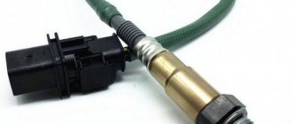
The latest generation ABS sensor is a coil with a semiconductor element installed in a stationary part of the hub. In the immediate vicinity of it, a toothed ring is attached to the brake disc, whose rotation is monitored by a sensor. It happens like this: the controller supplies voltage to the device, and it constantly changes the resistance due to the passage of a series of teeth on a rotating ring.
How ABS works on a car
The anti-lock braking system (ABS; Anti-lock braking system) is designed to prevent the car's wheels from locking.
The primary task of ABS is to maintain control of the car, its stability and controllability during unexpected braking. This allows the driver to make sharp maneuvers, which significantly increases the active safety of the vehicle.
Since the friction coefficient is reduced in relation to the rest coefficient, the car, when braking on locked wheels, will travel a much greater distance than on rotating ones. In addition, when the wheels are blocked, the car skids, depriving the driver of the chance to carry out any maneuver.
The ABS system is not always effective. On an unstable surface (loose soil, gravel, snow or sand), the immobilized wheels form a barrier of the surface in front of them, breaking into it. This significantly reduces braking distance. A car with studded tires on ice travels a greater distance when the ABS is activated than on locked wheels. This is explained by the fact that rotation prevents the spikes from crashing into the ice and slowing down the movement of vehicles. But at the same time, the car retains controllability and stability, which in most cases is much more important.
Wheel speed sensors are installed on the hubs
Equipment installed on individual vehicles allows the function of disabling ABS.
This is interesting! Experienced drivers in cars not equipped with an anti-lock braking device, when braking unexpectedly on a difficult section of the road (wet asphalt, ice, snow slush), jerk the brake pedal. In this way, they avoid complete blocking of the wheels and prevent the car from skidding.
Signs of sensor malfunction
The following symptoms indicate that the ABS sensor needs to be checked:
- when braking sharply or on a slippery road, the car moves “skid” and goes into a skid;
- there is no characteristic sound of ABS activation - frequent tapping or crackling from the side of a locked wheel (the type of noise depends on the make of the car);
- The anti-lock braking system warning light on the dashboard lights up.
If, for various reasons, the functionality of several sensors is disrupted, then the indicator for turning on the handbrake or a malfunction of the brake system additionally flashes on the instrument panel. You can continue to operate the car, but in slippery areas or during an emergency stop, the driver will have to work instead of ABS - often and sharply press the pedal.
What to do if a breakdown is detected
What to do with the ABS sensor if a malfunction is detected? If the problem point is the device itself, it will have to be replaced, but in the case of electrical wiring, you can fix the defect yourself. To restore its integrity, we use the “soldering” method, carefully wrapping the joints with insulating tape.
If the ABS indicator on the dashboard lights up, this is a clear sign of a sensor failure. The described steps will help identify the cause of the breakdown, but if you lack knowledge and experience, it is better to contact a car service center. Otherwise, illiterate diagnostics of the condition, coupled with improper repair of the device, will reduce the effectiveness of the anti-lock braking system and can provoke an accident.
An anti-lock brake system is an essential component of any modern car. Not all domestic drivers are accustomed to this technical equipment. But some have already learned not only to take advantage of its benefits, but also to independently diagnose the operation of the system.
The essence of ABC is that during emergency braking, the movement of all four wheels is prevented from blocking. This works to increase vehicle stability and reduce braking distance. It is especially important when driving on slippery surfaces - gravel, icy, wet asphalt. The car does not skid, the level of controllability remains high, although the brake pedal is pressed to the limit.
Key parts are a hydraulic unit that modulates fluid pressure, wheel speed sensors, their location, and a computer that processes information from the sensors and transmits it to the main unit. Location: under the hood, in the space between the brake cylinders.
How is the check performed?
If an ABS or brake system error appears on the dashboard, the reason does not always lie in the ABS sensor itself. To accurately identify the cause of the malfunction, it is recommended to conduct a comprehensive diagnosis of the vehicle. To save budget and time, the most preferable option would be self-diagnosis using an ODBII scanner.
If your budget is limited and you do not want to spend large sums on purchasing a device, we recommend that you pay attention to the Korean-made Scan Tool Pro Black Edition adapter.
This device sees not only the engine, like most budget scanners, but also other components and assemblies of the car (including ABS and the braking system). The scanner is compatible with most cars and connects to any device via Bluetooth or Wi-Fi. You can also use this device to check the operation of all sensors in real time.
Since the operation of a working ABS sensor is based on changes in electrical resistance when the wheel rotates, its parameters can be measured with a multimeter or a tester operating in ohmmeter mode. Conditions for diagnostics: a regular garage or a flat area, an inspection ditch is not required. From the tools, take a jack and a wheel wrench.
To check the ABS sensor with a tester, follow these steps:
- Place the car on a level surface and secure it with wheel chocks. The handbrake should not be applied.
- Jack up the rear wheel and remove it. Having found the wiring harness going to the sensor in the hub, find the connector and disconnect it. Clean all contacts thoroughly, preferably with a special liquid.
- Turn on the multimeter to measure resistance and take measurements in the block coming from the sensor. Depending on the brand of car, the value should be from 500 Ohm to 1.4 kOhm.
- Grab the drum or disc with your hand and spin it while watching the tester readings. The resistance must change.
- Switch the device to voltage measurement mode and turn on the ignition. Check the presence of DC current from the control unit by connecting a multimeter to the second part of the connector.
- Repeat the operation on all wheels.
On different car models, the connector may be located in different places - hidden under the bottom or plastic protection. To locate the block, probe the wiring harness by hand.
Checking the sensor resistance
Before starting the testing procedure, it is advisable to know the standard resistance value of the ABS sensors installed in your car. This information can be found either on the manufacturer's website or on the Internet. The algorithm for checking the sensor resistance is quite simple:
- We hang the wheel using a jack and remove it.
- We find the ABS sensor and disconnect its connector from the wiring leading to the control unit.
- We switch the multimeter to resistance measurement mode.
- We connect the probes to the contacts of the sensor connector and look at the readings of the device.
- If the ohmmeter shows “0”, this means that there is an open circuit in the sensor coil. This sensor must be replaced. Device readings that exceed the nominal value by 2–3 times also indicate a malfunction of the sensor, namely that its coil is “burnt” and the signals coming from it to the control unit are incorrect.
Advice! Typically, the resistance of passive induction sensors is in the range of 700÷2500 Ohms. If you are unable to find technical information about specific sensors installed in the car, you will have to check the resistance of all ABS sensors. Their simultaneous failure is unlikely. By comparing the results of all measurements taken, it will be possible to draw a conclusion about which specific sensor is “buggy” and replace only that one.
You can check the resistance of all sensors without removing the wheels. For this:
- We find the ABS control unit under the hood of the car.
- We disconnect from it the connector in which the wires from the sensors and other devices included in the anti-lock brake system are fixed.
- Next, we connect the multimeter probes to the corresponding contacts (to which the sensors are directly connected) and sequentially check the resistance of all sensors. The pinout of the connector can be found in the operating instructions or on the manufacturer's website.
On a note! This test method allows you to determine not only the resistance of the sensor coil, but also the serviceability of the wiring from the sensor itself to the control unit.
Analysis of diagnostic results
The problem with the ABS function does not always lie in the sensors. The culprits of system failure may also be the wires connecting the elements to the control unit. That is why it is necessary to carry out 3 measurements and draw the following conclusions based on the results:
- If the resistance of the ABS sensor tends to zero or, conversely, the device shows an infinity symbol, then there is a malfunction of the element itself. Another option is a violation of the insulation or a break in the section of conductors from the connector to the sensor.
- The tester shows that the resistance is within normal limits, but when the brake disc rotates, its value remains constant. There are two versions here: severe contamination of the gear ring (as an option - destruction) and, again, failure of the sensor.
- The absence of voltage in the supply line indicates a break in the electrical circuit coming from the controller.
In the first case, it is necessary to remove the device from the hub and inspect the wires for fractures, breaks or short circuits. To be sure, measure the resistance again, while moving the conductors. If the result is negative, buy and install a new part.
If the resistance remains the same, get to the gear ring, clean it thoroughly and inspect it. If you find mechanical damage, it is better to replace the spare part.
Advice. Sometimes unscrupulous or ignorant auto mechanics damage the ring when repairing the suspension, or even throw it away completely. When picking up your car from a mechanic, always check that this important part is present.
In the case when there is no voltage in the controller circuit, you should ring this section of the wiring. How to do it:
- Find out where the electronic control unit for the hydraulic valves is located. For example, in a Chevrolet Aveo it is located behind the brake fluid reservoir, and in a Renault Megane it is located on the side of the alternator drive belt.
- Remove the block from the ECU and clean the contacts. Find the pinout of the wires or track them by color.
- Place a shorting jumper on the block located near the wheel. Test the circuit with an ohmmeter or a regular light bulb with a battery.
The easiest way to find the ECU if there is no documentation for the car is to follow the brake pipes leading to the hydraulic unit. The latter stands next to the controller or is connected to it by a bundle of wires.
If an open circuit is detected, you will have to look for the defect along the entire line in order to eliminate it. The work is quite complex, so it should be entrusted to an experienced auto electrician.
Sensor Features
There are several significant differences between passive and active types. They are called passive because they do not require voltage to operate; such a sensor itself generates electrical impulses, to which the electronic unit reacts. Active elements require voltage to be applied to them.
Passive elements are very simple in design and are very reliable. That's why they are so common, despite their shortcomings.
Active types of sensors use microcircuits in the design, which complicates the element and makes it more vulnerable. But they are highly accurate and do their job even at low speeds.
Since all types of sensors operate under the influence of a magnetic field, it alone is not enough in the design; another element is needed to which it would react.
The induction (passive) type uses a ferromagnetic alloy pulse gear ring mounted on the drive hub or shaft, as well as on the steering axle. Previously, it could also be mounted on the bevel gears of the main drive.
In active types, a magnetic pulse ring is used. In the case of a magnetoresistive sensor, this ring is divided into alternating sectors with permanent magnets of different polarities.
But the Hall sensor uses a regular magnetic ring, without any sectors, integrated into the wheel bearing.
Alternative verification method
When you don't have a multimeter at hand, you can check the ABS sensor in a simpler way. It will work when only one element fails, and not several. Diagnostics is performed as follows:
- Disconnect the connector on one wheel sensor. Next, you need to start the engine and drive a few meters.
- If the second light on the brake system (or handbrake) malfunctions comes on, then the element being tested is operational. Connect the block and repeat the operation on the next wheel.
- If one sensor is broken, the ABS indicator lights up, and if there are two or more sensors, the handbrake lamp lights up. When the second indicator on the panel does not light up, it means that you have disconnected the faulty element.
The method allows you to determine the location of the problem, but not its nature. For a more accurate diagnosis, you need to use a tester with an ohmmeter.
Source
How to understand that the ABS is broken
In the simplest cases, the problem will be indicated by an indicator on the control panel. A sensor that lights up for 10 seconds turns on while driving and indicates a malfunction. In most cases, problems can only be identified while driving.
Before a thorough search, you need to exclude two points:
- recent tire change. Studded tires on the drive wheels increase the diameter, causing the rear and front elements to rotate at different speeds, which causes the malfunction sensor to light up;
- The abs sensor can also trigger slippage.
False signals have been eliminated, let's move on to serious malfunctions.