On the center console of Vesta there is a panel with several buttons (door locks, ESC disable button), the rest of the places are not used and there are plugs in their place. During modifications to the car (installation of a radar detector, video recorder, PTF, etc.), it may be necessary to install additional buttons. Do you know how to make functional buttons instead of blanks on the panel? Can buy a ready-made kit
for installation, below are instructions for those who decide to save money.
You will need: a tact button for breadboards for 6x6 soldering, a spring (diameter 5 mm, length 10 mm), M2 bolt (length 12 mm), hot-melt gun, soldering iron.
We remove the button panel from the Vesta center console, carefully prying it up with a screwdriver or a plastic spatula (there are latches around the entire perimeter).
All buttons and plugs have hinges on one side and latches on the other.
To disassemble the button panel, you will need to unscrew seven fastening screws (from the end - 3 pcs., at the edges - 2 pcs. and under the buttons - 2 pcs.), and release the latches at the edges.
In order for the plugs to have free movement, like a button, you should bite off the stops shown in the photo. The role of the pusher will be performed by a bolt with a spring, which we install in the panel as follows:
We solder two wires to the clock button and glue them under the plug with a heat gun, cutting off the side. We solder one wire to the “ground” on the board, and bring the second one out to the outside of the block.
If you decide to make the button closer to the center, then there is a special place on the board for the clock button. We solder it directly to the contacts, and connect the wires in the same way (one to ground to the board, the other to the outside).
If you need backlighting, then you will need SMD LEDs and 15 kOhm and 1.2 kOhm resistors. We place them next to the button, as in the photo:
Also, parts of another block of buttons (article 8450006943) can be used to make additional buttons along the edges. Connection diagram and result in the photo:
We reassemble in reverse order. In order not to forget what the new button means, you can order laser engraving or use stickers.
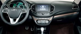
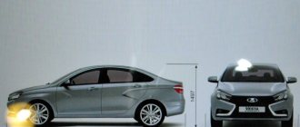
Description of the new instrument panel on the Lada Vesta
In 2021, the manufacturer began installing a new type of instrument panel on production Lada Vesta models.
Its distinctive features:
- increased font for display;
- the contours of the tachometer and speedometer arrows are outlined in orange;
- Illumination of the instrument panel on a permanent basis;
- The brightness level is adjusted using a mechanical button on the Lada Vesta panel;
- The volume level of alerts, warnings, and information signals has been increased;
- light indication when seat belts are not fastened;
- there is no need to adjust the clock mechanically; the synchronization process in Lada Vesta is automated;
- The temperature mode is displayed in stages.
Conclusion The new instrument panel is undoubtedly more informative than the previous one. Efficiency is positively assessed by many car enthusiasts. Owners of the first “generation” Lada Vesta with an old-style shield can, if desired, replace it with a new one. The fasteners and connectors are identical.
Implementation of a fixed button from a non-fixed one
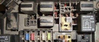
The standard buttons on the Vesta center console do not have locking and short the wires to ground. To use them in the operation of fog lights or any other equipment, you should use a relay, for example, rear fog lights (ZPTF), article number 23.3777.
| Contact no. | Function | Connection |
| 1 | Relay operating contact (input) (+) | Constant +12V via 10A fuse |
| 2 | Permissive signal (+) | +12 V from the ignition (or connect to No. 1 so that the button always works) |
| 3 | Total weight (-) | Wire from body |
| 4 | Relay operating contact (output “+” to load) | Output +12V |
| 5 | Control signal "on/off" (-) | “Ground” from a non-locking button. The button is placed in the wire gap (see diagram) |
| 6 | Permissive signal (+) | Not involved |
The purpose of the buttons can be anything, for example, turning on/off PTF, heated windshield, recorder/radar detector, or indicating a low level of washer fluid.
Photo: Phantom70, Raiven-Tumen and Phantom70 logbook
Key words: Lada Vesta torpedo
+6
Share on social networks:
Found an error? Select it and press Ctrl+Enter..
Functions and features of the Vesta panel device
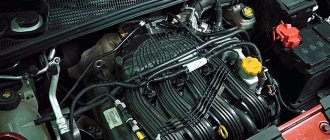
The instrument cluster on the Lada Vesta is completely different from those used on the Priora, Grant and Kalina. It is now a completely redesigned multifunctional device.
The speedometer is located in the central well - this is the main element of any “tidy” in a production car. The scale implies acceleration to 200 km/h, although in fact the stated maximum speed of Vesta with the current engine is no more than 185 km/h. Next to the speedometer there is a small on-board computer display, on which the driver can see all the necessary information about the operation of the engine and other vehicle systems.
Inside the speedometer scale there are various indicators that inform the driver about different parameters: the hazard warning lights are on and the direction indicators are on, the brake pads are critically worn, the engine is malfunctioning and the engine oil level is low. On the left is the tachometer well, the scale of which is marked from 1 to 7 (1000-7000 rpm). The engine allows you to “spin” up to 5500 rpm - this way there is no harm to the motor. After this mark there is a red zone; prolonged operation of the power unit at such high speeds is not recommended. The tachometer also contains information indicators.
In general, the instrument panel has an attractive design; the scales are backlit in green and orange with white numbers. The only drawback is the poor design of the arrow indicators. The intermediate divisions of the scales are not informative, and you need to get used to them. With a quick glance while moving, it will not be easy to read the readings.
- the numbers have become noticeably larger, reading readings while moving has become much easier;
- the backlight is used regardless of whether the lighting is on or not, the backlight is on on all scales at any time;
- instead of white backlight, red is used;
- a voice alert now warns of an unfastened seat belt; the audio also includes a GPS connection and much more;
- the volume of sound notification and voice guidance has increased (information and warning signals);
- the time on the display is now synchronized automatically by satellites of the ERA-GLONASS navigation system;
- The warning indicators have been changed (low tire pressure and unfastened seat belts front and rear).
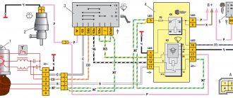
Wiring diagram Lada Vesta
Lada Vesta, like any other modern car, contains a lot of electronics. Its individual elements are connected by wiring several hundred meters long. The need to study the electrical circuit of the Lada Vesta may arise in various cases, from tuning to repair work. We invite you to familiarize yourself with these diagrams and their explanations.
Lada Vesta wiring diagram
A general wiring diagram is too cumbersome and difficult to understand, so diagrams are used to show the individual connections.
Please note that each diagram contains performance tables that indicate the designation of the harness in question depending on the vehicle’s configuration. The given wiring diagram of Lada Vesta is black and white, and the colors of the wires are indicated by letters
The decoding is in this table:
The Lada Vesta wiring diagram shown is black and white, and the colors of the wires are indicated by letters. The decoding is in this table:
Wire colors
Front wiring harness
Front harness Shows the location of the following elements:
- headlights;
- sound signals;
- cooling system fan;
- sensors (wheel speed, air temperature, hood position, etc.);
- engine control units and ABS;
- canister purge valve;
- alarm switch;
- windshield wiper drive;
- windshield heating element;
Rear wiring harness
Rear harness Displays the location of devices such as:
- additional body electronics units;
- sensors (rain, cabin air, wheel speed);
- interior lighting control unit;
- fuel tank.
Front doors
Front right door Front left door The connection of the following Lada Vesta elements is described:
- locks;
- lampshades;
- window regulators and their switches;
- speakers;
- mirror drives.
There are also switch blocks in the left door of Vesta.
Ignition system
Ignition system This harness connects all devices related to the operation of the ignition on the Lada Vesta:
- sensors;
- motor control controller;
- battery;
- generator;
- circuit breakers;
- timing control valve;
- reverse light switch.
Connection between battery and starter
Battery starter The engine starting and power supply system is shown. The circuit includes the battery, starter, generator and fuses.
Dashboard
Instrument panel The instrument panel of Vesta, as the most “stuffed” place, has a corresponding electrical circuit. This includes:
- sensors (steering angle, clutch pedal position);
- various relays (socket, fuel pump, heater fan, exterior lighting, power windows);
- various switches and switches;
- diagnostic connector;
- steering wheel keys;
- cigarette lighter;
- airbags;
- control units.
And a number of other electronic little things that can be listed endlessly.
Additional rear wiring harness
Additional rear wiring harness This Lada Vesta wiring diagram contains the following:
- parking sensor control unit;
- trunk lid lock drive;
- room lighting;
- trunk lighting;
- lights on the body and trunk lid;
- heated rear window.
Additional right rear wiring harness
Auxiliary Right Rear Wiring Harness This harness connects the following devices:
- sensors (side impacts, seat belts, passenger presence);
- airbag control;
- ATM and manual transmission switch;
- robotic gearbox selector.
Robotic gearbox
Additional harness The connection of the “robot” control elements is shown:
- actuators of the clutch engagement mechanism, gear selection and gear shifting;
- input shaft speed sensor.
Conclusion
Some Lada Vesta electrical circuits may seem extremely confusing to a beginner. But gradually, by comparing them with the electronics connections in the car, you will be able to get comfortable and not be afraid to make any upgrades, like a real electrician.
vesta-site.ru
What are the steering column switches responsible for on the Lada Vesta?
The devices are equipped with a large block of buttons. The first function that attracts car owners is PTF. In the Renault version, the fog lights are turned on with the side lights. The original configuration works with low beam. The changes are justified by the traffic rules of the Russian Federation. According to Article 19.4, the use of PTF is permissible with low or high beam headlights. Most car enthusiasts prefer DRLs when using fog lights in poor visibility conditions.
The Renault PP configuration allows the use of PTF with low beam. You will have to re-solder the mechanism by connecting the black wire to the terminal of the desired mode. When changing the internals, remember that you cannot return a “modified” part under warranty.
The handles are equipped with a wiper button. The operation of the wipers is controlled by a rain sensor. If you need to wipe away splashes from a passing truck, you will have to turn off the windshield wiper manually. The one-time swing function, launched by lightly pressing, is not provided by production.
The Lada system allows owners to adjust the volume of the turn signals by going to hidden settings. Press the right wiper control lever buttons and hold for five seconds.
How to disassemble the door of a Lada Vesta
The doors of cars of the Lada Vesta family are covered with decorative plastic and suede inserts; these parts can be removed independently. Owners often resort to this type of work when eliminating squeaks in doors or when they want to install additional sound speakers in the rear doors. Dismantling the front and rear doors is practically the same, the only difference is in the method of removing the window handle (if a mechanical device is installed on the rear doors) or in the button block (with an automatic window lift). Before starting work, it is recommended to acquire plastic pullers; with the help of pullers, all decorative elements of the car are removed without leaving any damage to them.
We begin removing the door handle trim from the door handle (see photo above), pry it off using a puller and gently pull it towards you, the trim is held in place by plastic clips that snap off with a little force. Removing the trim is a key point in disassembling the casing; the fact is that behind this trim there are two bolts holding the casing.
We remove the door handle plug to the side and proceed to unscrew the bolts with a 10mm wrench. After the bolts are unscrewed, you have to remove the window handle:
or pull out the button block (if your Lada Vesta has automatic windows). The window lifter handle also does not have additional fasteners and is removed using one puller:
With the thumb of your left hand, gently press on the handle, while with the other hand we install the puller in the resulting hole (note that the puller is not installed between the door trim and the window handle, but in the middle of the handle) and gently pull it towards you, thus pulling out the core of the handle (see photo below). We finish the analysis by unscrewing the last bolt, which is located at the bottom of the casing.
We finish the analysis by unscrewing the last bolt, which is located at the bottom of the casing.
To unscrew this bolt, you will need a Torx 20 star screwdriver. Now the door trim is held in place only by plastic clips located around the perimeter.
Assembling the door on a Lada Vesta car is carried out in the reverse order. The trim is installed and snapped into place with clips, after which we tighten the bolts and install the window handle in place.
How to remove the steering column switch on Lada Vesta
- To disassemble the device, it is not necessary to remove the entire unit. Disconnect the levers by unscrewing the screws and pulling out the seal.
- To manipulate the entire unit, you will have to remove the steering wheel and airbag. Disassembly takes five minutes.
- First, remove the plastic housing that sits on top of the steering column by removing two screws.
- While holding the structure, remove the last two bolts.
- Place small parts in a safe place.
- Disconnect the wire from the seal.
- Installation of the Vesta PP occurs in the reverse order.
Designation of light bulbs and sensors on the tidy
First, let's take a look at the location and description of the components of the dashboard in the Lada Vesta:
Tachometer. Thanks to this device, the driver knows what the crankshaft operating frequency is, that is, at what speed the engine operates. Do not allow the instrument needle to move into the red zone, as this may lead to damage to the power unit. If you press the gas pedal to the floor, while the speed exceeds 6200 rpm, the fuel supply will be limited. Experts also recommend not allowing the engine to operate in a dangerous mode, when the speed is less than 800 per minute. "Pedal adjustment" indicator. The seat belt icon is always on if the driver or passenger is not fastened. Airbag indicator. If it appears for no reason, the problem may be a failure of the airbag sensor or its poor contact with the electrical network. A backup light bulb can be connected when installing additional devices or systems. Brake failure indicator; when it appears, you should stop the car and check that the brakes are working properly. The trunk door is unlocked icon; when it appears, you should check the trunk. Unlocked hood symbol. If it starts to light up on the dashboard, while the hood is normally closed, you need to check the functionality of the sensor. Speedometer
This device is considered one of the main ones, since the driver pays attention to it more often than others. The device is used to demonstrate the speed of movement. The hazard warning light icon always flashes when the hazard lights are activated. Unlocked doors symbol
If the car starts moving with one or more doors open, a corresponding light will appear on the dashboard. Cruise control system indicator. The speed limiter indicator appears if the driver exceeds the permissible speed. This device indicates the temperature of the antifreeze in the cooling system. If the indicator fails, the vehicle cannot be operated as it reports the engine temperature. If this value exceeds the permissible value of 115 degrees, the light will light red without interruption, and the buzzer should also sound briefly. At high temperatures, the engine may simply fail. Icon of the standard anti-theft system - immobilizer. Icon for turning on side lighting. Symbol for switching on low beam. LED high beam activation icon. The indicator for turning on the front PTFs always appears when they are activated. The icon for turning on rear-mounted foglights is similar. ESC light - electronic stability control system. The ESC OFF symbol indicates that the system is turned off. The fuel level sensor in the tank is used by the driver to guide him when he needs to refuel the car. The reserve fuel volume activation icon appears when there is little gasoline left in the tank. LCD display with main parameters and options. The right turn signal icon stops flashing after the maneuver is completed. Left turn signal activation symbol. ABS system activation lamp.
The battery icon may always appear when the ignition is turned on, but should disappear after starting the engine. If the indicator remains on, this indicates the need to charge the battery or diagnose the generator unit. The light indicator for emergency low tire pressure receives data from the corresponding sensors installed in the wheels. Symbol of problems with the gearbox. Icon of faults detected in the operation of the motor. There can be many reasons; when a symbol appears, more detailed diagnostics are required. Electric power steering controller. Symbol of emergency low oil pressure in the internal combustion engine. It also always appears when the ignition is turned on and disappears after the engine starts (the author of the video is Yuri T*********O).
Instrument cluster. Signal lamps
The instrument cluster includes:
1 – tachometer. Shows the engine crankshaft speed (x1000 min-1). The presence of the tachometer needle in the red scale area warns of increased engine speed. To prevent damage to the engine, its maximum speed is limited by the electronic engine management system software.
Above approximately 6200 min-1 the fuel supply will be limited. Possible interruptions in engine operation and jolts in the movement of the vehicle are not a malfunction. When the rotation speed decreases, the fuel supply will resume. Also, do not allow the engine to operate when starting off or while driving at an engine speed below 800 min-1.
ATTENTION!
It is prohibited to operate the engine in a dangerous mode (at engine crankshaft speeds above 6200 min-1 and below 800 min-1).
2 – indicator “Pedal adjustment” (see section “Operation of the vehicle”).
3 – “Seat belt” indicator (see section “Airbag system”).
4 – indicator “Airbag system malfunction” (see section “Airbags”).
5 – reserve.
6 – indicator “Brake failure” (see section “Driving a car”, “Braking and parking”).
7 – indicator “Unclosed trunk” (see section “Body and interior”).
8 – indicator “Hood not closed” (see section “Body and interior”).
9 – speedometer, shows the vehicle speed (km/h).
10 – “Hazard Alarm” indicator.
11 – indicator “Doors not closed” (see section “Body and Interior”).
12 – indicator “Cruise control” (see section “Operation of the vehicle”).
13 – indicator “Speed limiter” (see section “Operation of the vehicle”).
14 – indicator and indicator “Coolant temperature” (section “Engine overheating”). Operating a vehicle with a faulty warning light is prohibited. When the operating temperature of the coolant is exceeded (more than 115°C), the indicator lights up red constantly, and a short-term intermittent buzzer sounds. Do not allow the engine to operate in overheating mode.
List of firmware for Lada Vesta instrument panel
Previous firmware versions are not compatible with subsequent ones. This must be remembered when upgrading yourself. Incorrect selection of the version will damage the electronic engine control unit (ECU) and on-board computer.
| Software version | Gearbox type | Transmission |
| Lada Vesta 026 | 8450007022 | Manual transmission |
| 028 | 8450007022 | Manual transmission |
| 035 | 8450007022 | AMT |
| 036 | 8450007022 | Manual transmission |
| 019 | 8450030825 | Manual transmission |
| 022 | 8450030825 | AMT |
| 027 | 8450030825 | Manual transmission |
As of March 2021, the firmware of the instrument panel on the Lada Vesta and the activation of the backlight in DRL mode are not carried out due to identified errors in the software.
Conclusion
Installing new generation firmware is extremely important for monitoring instrument performance, monitoring engine temperature, and reducing eye strain.
During the flashing process, be extremely careful not to break the sequence of actions. Remember about the compatibility of new generation firmware. If you encounter any difficulties during the upgrade, contact a service station specialist for help.
Do-it-yourself firmware
You need to be aware that all actions are performed at your own peril and risk. No one can guarantee that after installing the firmware yourself, the device will work correctly. To prevent this outcome, it is recommended to update the panel either at an authorized dealer or at specialized service stations.
The cost of such a service varies from 1,500 to 2,500 thousand rubles. This is much cheaper than buying a new shield to replace a damaged one yourself. For dismantling and reflashing, the warranty may be revoked if the procedure is not carried out by an authorized dealer. If you decide to update the software yourself, you will need to make a backup copy of the standard firmware, then prepare the necessary tools:
- A device for flashing Usbdm OSBDM V4.95 - can be ordered on AliExpress, the cost is approximately 600-700 rubles.
- Install drivers and software for Windows from the disk included with the programmer.
- Dismantle the instrument panel, peel off the factory seal, and remove the cover from the back.
- Open the programmer and move the checkbox to the 3.3V position - at this voltage you will not need an external power source.
- Connect to the dashboard and PC.
- On a computer or laptop, open the HCS12 Programmer program, select and click on the “Detected” item.
- Go to the “Target” item and select the folder with the location of the firmware, check the box next to the “Auto Reload” item, then click on “Detect Chip”. The programmer will determine the chip type automatically.
- Go to the “Security” tab and check the “Unsecure” box.
- In the “Advanced” tab, check the “Enable” box.
- In the “Device Operations” section on the “Target” tab, select the “Erase Selective” item - only the firmware will be replaced, the immobilizer data and mileage will be saved.
Now you can click on the “Program Flash” button - the firmware process will start. This will last a few seconds. After completion, when prompted by the program to connect the dashboard, click “No”. The flashing device can be turned off and the instrument panel replaced.
Lada Vesta dashboard firmware
Before installing the firmware, remember that it is quite possible that it will not work correctly. Therefore, it is better to do this from official dealers. If you decide to do it yourself, then you will need a Usbdm OSBDM V4.95 programmer and a computer or laptop.
Here are 12 step-by-step instructions for installing the firmware:
- Install the driver and firmware program on the PC from the disk that comes with the device.
- Remove the instrument panel, peel off the factory warranty seal and open the back cover.
- Open the device and set the switch to 3.3 volts.
- Connect the device to the panel and computer.
- Launch the HCS12 Programmer program on your PC and click on Detected.
- In the Target item, specify the folder in which the firmware is located. Check the Auto Reload box and click Detect Chip. In this case, the chip type is determined automatically.
- On the Security tab, check the Unsecure box.
- On the Advanced tab, check the Enable box.
- Go to the Device Operations section, on the Target tab, select Erase Selective. With this choice, mileage and immobilizer data are saved.
- Click on the Program Flash button to launch the firmware. This will take a few seconds.
- Refuse to connect the panel in the program.
- Now you can turn off the device and install the device in its place.
Wiring
Main terminal on the button block.
Black - mass. We connect anywhere to the body. Red - 12th century We connect to the Red one on the terminal from the lock. We connect brown with white - turn on the ignition. Connect to pink/black Yellow - starter. Connect to yellow/blue. Blue - ACC (first position to turn on the radio) Connect to red / white Connector with two wires (brown and green) Brown is not used Green - brake pedal. Connect with the green one on the brake pedal sensor. Button labels can be disabled. We bring it to the antenna, wait for short signals, do not remove the mark, wait for two more longer signals, remove the mark. Now you can use the button without labels. (Convenient when the car is in service) It’s easy to get the tags working again. Apply the tag and remove it after the signal. The tags are activated. There is a StarLine a93 signaling. After installing the button, autorun works. IMPORTANT regarding autostart: on a manual transmission, in order to activate autostart, the immobilizer chip (standard) must be attached. Only then can you press the brake pedal and briefly press the button.
IMPORTANT regarding the immobilizer and tag antennas: They should be at a distance no closer than approximately 25-30 centimeters. Otherwise, the regular one stops seeing the key chip.
Sorry for the Russian language, I didn't study well. I loved to go for walks)))) If you don’t understand, ask here in the comments to the post.
Read more: Detailing center what is it
One of the features of expensive cars is the presence of an engine start/stop button instead of the usual ignition key. AvtoVAZ does not yet provide the “Start the engine with a button” option, but any owner of a Lada car can modify the design with their own hands.
Below are two diagrams for connecting the start/stop button:
- Installation of a ready-made kit with a button, control unit and wires (price about $35), see the Aliexpress catalog;
- Self-production of one of the most popular circuits based on automotive relays (costs about $6).
In both cases, the scheme can be implemented on any Lada car (XRAY, Vesta, Largus, Granta, Kalina, Priora or Niva 4x4), including foreign cars. The button is installed in place of the ignition switch.
The ignition switch can be:
- put away;
- leave. Connect the start/stop button to the ignition switch connector (allows you to return to the key-start scheme within 10 minutes), and to prevent the steering wheel from being blocked, leave the key cut off and turned in it.
Do-it-yourself firmware
You need to be aware that all actions are performed at your own peril and risk. No one can guarantee that after installing the firmware yourself, the device will work correctly. To prevent this outcome, it is recommended to update the panel either at an authorized dealer or at specialized service stations.
The cost of such a service varies from 1,500 to 2,500 thousand rubles. This is much cheaper than buying a new shield to replace a damaged one yourself. For dismantling and reflashing, the warranty may be revoked if the procedure is not carried out by an authorized dealer. If you decide to update the software yourself, you will need to make a backup copy of the standard firmware, then prepare the necessary tools:
- A device for flashing Usbdm OSBDM V4.95 - can be ordered on AliExpress, the cost is approximately 600-700 rubles.
- Install drivers and software for Windows from the disk included with the programmer.
- Dismantle the instrument panel, peel off the factory seal, and remove the cover from the back.
- Open the programmer and move the checkbox to the 3.3V position - at this voltage you will not need an external power source.
- Connect to the dashboard and PC.
- On a computer or laptop, open the HCS12 Programmer program, select and click on the “Detected” item.
- Go to the “Target” item and select the folder with the location of the firmware, check the box next to the “Auto Reload” item, then click on “Detect Chip”. The programmer will determine the chip type automatically.
- Go to the “Security” tab and check the “Unsecure” box.
- In the “Advanced” tab, check the “Enable” box.
- In the “Device Operations” section on the “Target” tab, select the “Erase Selective” item - only the firmware will be replaced, the immobilizer data and mileage will be saved.
Now you can click on the “Program Flash” button - the firmware process will start. This will last a few seconds. After completion, when prompted by the program to connect the dashboard, click “No”. The flashing device can be turned off and the instrument panel replaced.