Connection diagram for generator in VAZ cars
The generator in cars is designed to generate electricity and charge the battery. If the normal operation of a car electric generator is disrupted, the battery begins to discharge and soon the car will stop starting completely - there is not enough battery charge. This device consists of a three-phase diode bridge, which, in turn, has 6 silicon diodes. Electrical voltage is created by the excitation of the rectifier at the moment when the rotor poles change under the stator windings. When the rotor rotates inside the machine stator, the poles of the rotor change. To increase the value of magnetic fluxes, the stator contains an electromagnetic exciting winding in the area of the magnetic cores. Marking and designation of wires:
- P - pink.
- F - purple.
- O - orange.
- B&W - black and white.
- KB - brown and white.
- CHG - black and blue.
- K - brown.
- H - black.
- B - white.
Connection diagram for the VAZ-2101 generator
Structurally, generator 2101 consists of the following main elements:
- The rotor is a moving part that rotates from the engine crankshaft. Has an excitation winding.
- The stator is the stationary part of the generator and also has a winding.
- Front and rear covers , inside of which bearings are installed. They have eyelets for attaching to the internal combustion engine. The back cover contains a capacitor necessary to cut off the alternating current component.
- Semiconductor bridge - called a “horseshoe” for its similarity. Three pairs of semiconductor power diodes are mounted on a horseshoe-shaped base.
- A pulley on which the VAZ-2101 generator belt is placed. The belt is V-shaped (on modern cars a multi-ribbed belt is used).
- The voltage regulator is installed in the engine compartment, away from the generator. But still it must be considered part of the structure.
- The brushes are mounted inside the generator and transmit the supply voltage to the field winding (on the rotor).
Electrical circuits of the VAZ 2106 car
Its design consists of a pair of brushes made of graphite, springs that allow them to be pressed more tightly to the rings on the rotor, as well as a brush holder. Loosen and remove the drive belt. Disconnect the block with wires from the generator connector. Contents: How to connect a standard generator G Replacing a VAZ generator with a G Refining the generator G for a VAZ Checking the functionality of the power supply system Electrical diagram of a VAZ As a matter of fact, if we look at the electrical diagram of a VAZ, which we have given below just in case, it turns out that it differs only from the diagram the presence of additional electrical appliances, which entailed some changes.
Conclusion Now you know what elements the VAZ generator consists of
The rectifier unit looks like a large horseshoe into which semiconductor elements are pressed. Consequently, electrical energy is generated. To do this, it is necessary to de-energize all current consumers of the car and increase the engine speed to 2.5 thousand.
Therefore, install a mudguard that will protect your car from moisture.
No generator can do without a rectifier unit and a voltage regulator.
In this case, significant current flows through the valves and they are damaged. How is it better than the standard six? GENERATOR VAZ 2101 BATTERY CHARGING LAMP AND PRINCIPLE OF OPERATION
Read more: Measuring electrical laboratories
Connection diagram for the VAZ-2107 generator
1 - battery; 2 - negative diode; 3 - additional diode; 4 - generator; 5 - positive diode; 6 - stator winding; 7 - voltage regulator; 8 — rotor winding; 9 — capacitor for suppressing radio interference; 10 — mounting block; 11 — battery charge indicator lamp in the instrument cluster; 12 - voltmeter; 13 — ignition relay; 14 - ignition switch.
Connection diagram for the VAZ-2108 generator
The VAZ-2108 generator has a rather massive stator winding, since it uses a large cross-section wire. It is with its help that electricity is generated. The wire is wound evenly over the entire inner surface of the stator into recesses specially provided for this purpose in the magnetic core. It’s worth talking about the latter separately. The middle part, the generator stator, consists of a series of thin metal plates pressed tightly together. They are often boiled on the outside to prevent separation.
What is contactless ignition and its advantages
Another interesting option for tuning classic models is installing a contactless ignition type. Definitely, the car only benefits from such an innovation - the engine runs smoother, dips disappear when accelerating the car, and it is much easier to start the engine in cold weather. In addition, there are savings associated with fuel consumption.
The wiring diagram on the VAZ 2106 in this case is almost identical: the main differences are the presence of a pulse sensor and the absence of a distributor. While the engine is running, the sensor creates pulses that enter the transistor switch.
Already with its help, other impulses are generated, characteristic of the primary winding on the coil. With interruption, the secondary winding produces high voltage current. From the distributor contact, current is supplied to the spark plugs in the required sequence.
So, you purchase a non-contact ignition package for a VAZ “classic”, which must match the characteristics of the car’s engine. Next, we will need a wiring diagram for the VAZ 2106.
Diagram of the EPHH carburetor system 2108, 21081, 21083 Solex
The following spare parts should be included in the configuration of such an ignition:
- switching unit;
- coil;
- high voltage wiring kit;
- spark plugs - DVRM;
- connecting wires.
Stages of work
To successfully replace the ignition with a contactless one, it is important to adhere to the principles of following the correct work technology. Remove the negative terminal from your battery
Any type of electrical repair should always begin with this action.
This is where the wiring for the VAZ 2106 will come to the rescue:
- We disconnect the wires and the main high-voltage wire from the ignition coil.
- Remove the distributor cover.
Be careful not to damage other wires
- The slider should be placed so as not to disturb its necessary settings.
- The mark on the block is placed where there are slots at the bottom of the distributor body.
- Unscrew the nut and take out the old distributor of the previous contact ignition system.
- Before installing the new system, open the cover of the updated distributor and place the slider in the same position as on the old distributor. You can put it in the hole in the block head.
- Move the mark to the required level and tighten the nuts.
Now you can assemble, as the VAZ 21063 wiring diagram suggests - put on the cover, connect the high-voltage wires. You can begin to dismantle the old ignition coil (this was discussed above).
- We install a new coil and connect another outlet of the high-voltage wire to it.
- Now we put all the high-voltage wires in their places. We will need pin “K” for the brown wires of the new coil, while the blue wires will go to pin “B”.
- You need to choose a place to place the switch, most often this is done in the area of the washer reservoir. It is secured with self-tapping screws.
The VAZ 2106 wiring has been replaced, you can tighten the wires with electrical tape. All that remains is to start the engine and adjust the operation of the ignition system.
The first thing you should pay attention to in this case is the integrity of the wiring, including high-voltage, as well as the serviceability of other elements of the ignition system. Spark plugs are checked on a separate stand
In some cases, the cause may be a faulty VAZ 2106 generator and the wiring to it.
Connection diagram for the VAZ-2109 generator
- Alternator. The 37.3701 or 94.3701 series can be installed.
- Negative diode.
- Additional diode.
- Positive diode.
- Alternator warning lamp, also known as battery discharge lamp.
- Instrument cluster.
- Voltmeter.
- Relay and fuse box located in the engine compartment in the compartment between the engine and the vehicle interior.
- Additional resistors built into the fuse mounting block.
- Ignition relay.
- Egnition lock.
- Accumulator battery.
- Capacitor.
- Rotor winding.
- The voltage relay is located in the engine compartment.
Windshield wiper and washer circuit (1980-1984)
- Washer motor;
- Windshield wiper and washer switch;
- Wiper relay;
- Wiper motor;
- Ignition switch;
- External lighting switch;
- Fuse box;
- Accumulator battery;
- Generator;
A - Jumper in the wires going to the windshield washer pump;B - The order of conditional numbering of plugs in the relay blocks and the wiper motor.
Connection diagram for the VAZ-2110 generator
On VAZ-2110, 2111 and 2112 cars, a 94.3701 generator was installed with a maximum output current of 80 Amperes and a voltage = 13.2–14.7 Volts.
Here is a breakdown of the connection diagram for the generator on the ten :
- Battery 12V;
- generator 94.3701;
- mounting block;
- egnition lock;
- battery charge indicator lamp in the instrument cluster
How to check the generator yourself
How to check a VAZ generator using the example of model 2109. Generator type 94.3701 alternating current, three-phase, with a built-in rectifier unit and an electronic voltage regulator, right-hand rotation.
Generator connection diagram . The voltage to excite the generator when the ignition is turned on is supplied to terminal “D+” of the regulator (terminal “D” of the generator) through indicator lamp 4 located in the instrument cluster. After starting the engine, the excitation winding is powered by three additional diodes installed on the generator rectifier block. The operation of the generator is controlled by a warning lamp in the instrument cluster. When the ignition is turned on, the lamp should be on, and after starting the engine, it should go out if the generator is working. If the lamp is brightly lit or glows half-lit, it indicates a malfunction.
The “minus” of the battery should always be connected to ground, and the “plus” should always be connected to the “B+” terminal of the generator. Failure to turn the battery back on will immediately cause increased current through the generator valves and damage them.
It is not allowed to operate the generator with the battery disconnected. This will cause short-term overvoltages to occur at the “B+” terminal of the generator, which can damage the generator voltage regulator and electronic devices in the vehicle’s on-board network.
It is prohibited to check the functionality of the generator “for spark” even by briefly connecting the “B+” terminal of the generator to ground. In this case, significant current flows through the valves and they are damaged.
1.2. Sidelights. 3.4. Exterior lights. 5. Interior lights. 6. Sound signals. 7. VAZ 2103 ignition distributor. 8. VAZ 2103 spark plugs. 9. VAZ 2103 generator. 10. VAZ 2103 battery. 11. Relay for turning on sound signals. 12. Ignition coil of VAZ 2103. 13. Side direction indicators. 14. Coolant temperature indicator sensor for VAZ 2103. 15. Oil pressure warning lamp sensor for VAZ 2103. 16. Brake fluid level warning lamp sensor for VAZ 2103. 17. Battery charging relay for VAZ 2103. 18. Headlight switch relay. 19. Carburetor valve VAZ 2103. 20. Oil pressure indicator sensor VAZ 2103. 21. Engine compartment lamp. 22. VAZ 2103 starter. 23. Voltage regulator. 24. Cartridge for connecting a portable lamp. 25. VAZ 2103 fuse block. 26. Relay - turn signal breaker. 27. Brake light switch. 28. carburetor air damper warning lamp switch. 29. Washer pump switch. 30. Relay - breaker of the warning lamp for turning on the handbrake. 31. Control lamp switch for turning on the handbrake. 32. Reversing light switch. 33. VAZ 2103 windshield wiper electric motor. 34. VAZ 2103 windshield wiper relay. 35. Glove compartment lighting lamp. 36. Courtesy light switch located on the front door pillars. 37. Front door opening warning light switch. 38. Fuel level indicator VAZ 2103. 39. Indicator lamp for fuel reserve indicator VAZ 2103. 40. Illumination lamp for the fuel level indicator. 41. Liquid temperature indicator in the VAZ 2103 engine cooling system. 42. Illumination lamp for the liquid temperature indicator. 43. Oil pressure indicator VAZ 2103. 44. Indicator lamp for insufficient oil pressure VAZ 2103. 45. Lighting lamp for the oil pressure indicator. 46. Tachometer illumination lamp for VAZ 2103. 47. Indicator lamp for turning on the hand brake and insufficient fluid level in the reservoirs of the hydraulic brake drive system. 48. Indicator lamp for carburetor air damper control. 49. Battery charging indicator lamp. 50. Tachometer VAZ 2103. 51. Indicator lamp for turning on the side light. 52. Indicator lamp for turning on the direction indicators. 53. Indicator lamp for turning on the high beam headlights. 54. VAZ 2103 speedometer lighting lamp. 55. External lighting switch. 56. Instrument lighting switch. 57. Three-position wiper switch. 58. Ignition switch. 59. Electric clock VAZ 2103. 60. Clock lighting lamp. 61. Three-position heater motor switch. 62. Front door open warning lamp. 63. Headlight switch. 64. Turn signal switch. 65. Horn switch. 66. Cigarette lighter. 67. Courtesy light switch located in the rear door pillars. 68. Interior lighting of the body. 69. Electric heater motor. 70. Trunk lamp. 71. Sensor for fuel level indicator and fuel reserve indicator for VAZ 2103. 72. Turn indicator lamp. 73. Double-filament indicator lamp and brake light. 74. Reversing light. 75. License plate lights. 76. Ground connection point. 77. Electrical connector.
Replacement and removal of the electric generator
The generator on a VAZ car is removed either for complete replacement in case of failure or to carry out repair work to replace faulty parts. To perform dismantling, prepare a standard set of tools; it is advisable to drive the car into the inspection hole.
- Disconnect the battery.
- Remove the protective rubber cap from terminal “30” and unscrew the nut and remove it from the wire stud.
- Disconnect the block with wires from the generator connector.
- We loosen the tightening of the generator to the adjusting bar, then lift it all the way up to the cylinder block and remove the belt from the pulleys.
- Completely unscrew the bolt securing the adjusting bar to the cylinder block, then from the bottom of the car unscrew the 2 bolts securing the lower bracket to the block and remove the generator, pulling it out of the engine compartment.
Source
Reasons for repairing the ignition switch
The ignition switch of the “six” has 4 modes with different functionality:
- Mode “0” allows you to power only wires 30 and 30/1. Other functions are disabled.
- Mode “I” makes it possible to operate the running lights, fog lights, wiper drive, and heater motor.
- Mode “II” - in this case, the electrical wiring on the VAZ 2106 activates the turn signals, instrument panel and ignition system.
- The “III” position of the key provides power to terminals 30/1 and 30-INT. The car starter is working.
Replacing the ignition switch yourself may be necessary for several reasons:
- Firstly, this is possible in case of loss of keys.
- Secondly, over time, the ignition switch cylinder wears out, and this affects engine starting.
- In addition, there may be problems with the contact wire group, which can lead to a short circuit.
On cars of the “classic” family, the location of the lock is below and to the left of the steering wheel. Also see the article about the restoration of domestic classics.
And it consists of the following elements and parts:
- lock body;
- contact disk;
- locking rod;
- roller and contact sleeve;
- block.
Dismantling the old unit
The instructions for repairing the lock yourself will look something like this:
Replacing the ignition switch on a VAZ 2106
- disconnect the battery;
- unscrew the fastening screws of the plastic casing under the steering column and remove it;
- disable the anti-theft device, for which you need to insert the key to position “0”;
- VAZ 2106 wiring requires removing the lock - for this purpose, insert an awl into the hole and unclip the latch;
- after you have removed the lock (see video), it is strongly recommended to mark the contact wires so as not to mix them up when connecting them back;
- install the new lock in the reverse order.
Replacing the contact group
The VAZ 2106 wiring diagram is designed in such a way that if it is necessary to repair the contact group, this can be done without dismantling the ignition switch. However, if you can remove it, you will almost certainly not be able to put it back. For this reason, we will need to perform all of the above operations.
It is recommended to purchase only high-quality spare parts, and it is better to do this from trusted car dealers, since today there are many fakes on sale. The distinctive properties of the original ignition switch will be the following:
- the body is cast carefully and with smooth edges;
- the top of the lock is rolled evenly;
- a wide hologram cannot be torn off without destroying it;
- free movement of the key in the cylinder, without interference.
Generator
Device
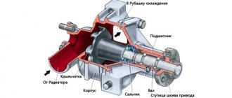
Cars are equipped with a three-phase alternating current generator G221. The main parts of the generator are a stator 19 with two covers 1 and 17 made of aluminum alloy, fastened with four bolts, and a rotor with winding 18. The rotor rotates in two closed ball bearings 6 and 16. The lubricant is added to the bearings during their manufacture and does not require replenishment during operation.
The generator rotor is driven by pulley 13 using a V-belt drive from the crankshaft pulley and consists of a shaft 7 with a steel sleeve 15 and steel beak-shaped poles 14 and 21 pressed onto it, forming, together with the shaft and sleeve, the core of the electromagnet. A rotor winding 18, called the excitation winding, is wound on a steel sleeve between the beak-shaped poles in a plastic frame. The ends of the winding are connected to slip rings 5 mounted on a plastic sleeve pressed onto the rotor shaft.
Electrical equipment VAZ
Device
Cars are equipped with a three-phase alternating current generator G221. The main parts of the generator are a stator 19 with two covers 1 and 17 made of aluminum alloy, fastened with four bolts, and a rotor with winding 18. The rotor rotates in two closed ball bearings 6 and 16. The lubricant is added to the bearings during their manufacture and does not require replenishment during operation.
The generator rotor is driven by pulley 13 using a V-belt drive from the crankshaft pulley and consists of a shaft 7 with a steel sleeve 15 and steel beak-shaped poles 14 and 21 pressed onto it, forming, together with the shaft and sleeve, the core of the electromagnet. A rotor winding 18, called the excitation winding, is wound on a steel sleeve between the beak-shaped poles in a plastic frame. The ends of the winding are connected to slip rings 5 mounted on a plastic sleeve pressed onto the rotor shaft.
Current is supplied to the field winding through brushes 11 and 12, pressed by springs to the slip rings. The brushes are made of a copper-graphite mixture and are located in a plastic brush holder 10. One of the brushes is connected to the generator housing, and the other to plug “67”.
The stator 19 is made of electrical steel plates 1 mm thick, connected by electric welding. On the inside of the stator there are 36 semi-closed slots, insulated with varnish or electrical insulating cardboard. A three-phase winding 20 is placed in these grooves, secured from falling out with wooden wedges or plastic tubes. Each phase winding consists of six continuously wound coils. The phase windings are connected in a “star” with terminal 9 of the zero point. The battery charge indicator relay is connected to it.
The alternating voltage induced in the stator winding is converted into direct voltage by a rectifier assembled on six silicon valves of the VA-20 type in a three-phase bridge circuit. In order to simplify the rectifier mounting details, three valves have a “-” rectified current on the housing (these are valves of direct polarity - positive), and three valves have a “-” rectified current (reverse polarity valves - negative).
Negative valves 3 (marked with black paint) are pressed into the cover 1 of the generator, and positive valves (marked with red paint) are pressed into a special plate - radiator 2, secured with screws 4.
A rectifier unit is installed on some of the generators, consisting of two plates with valves pressed into them. The generator set connection diagram is shown in Fig.
Generator specifications
Maximum recoil current at 14 V and rotor speed 5000 min-1, A - 42 Maximum rotor speed, min-1 - 13000 Gear ratio between the crankshaft and the generator - 1:2.04
Inspection and operation rules
When operating, maintaining and repairing the generator, observe the following rules, violation of which may lead to damage to the voltage regulator or rectifier valves.
The “-” terminal of the battery should always be connected to ground, and the “+” terminal should always be connected to terminal “30” of the generator. Incorrectly switching the battery back on will immediately cause an increased current through the generator valves and cause them to fail.
It is not allowed to operate the generator with the 30 consumer wires disconnected from the terminal (especially with the battery disconnected) - this will cause a dangerous increase in voltage on the valves and they may be damaged.
It is prohibited to check the functionality of the generator for a “spark” even by briefly connecting terminal “30” of the generator to “ground” or plug “67”. In this case, a significant current flows through the valves and they break through. The generator can only be checked using an ammeter and voltmeter.
It is prohibited to check the charging current circuits with a megohmmeter or a lamp powered by a voltage of more than 36 V. If such a check is necessary, then first disconnect the wires from the generator and voltage regulator.
The quality of stator insulation with increased voltage is checked only on a stand and always with the terminals of the phase windings disconnected from the valves.
When electric welding components and parts of the car body, disconnect the wires from all terminals of the generator and battery.
Control checks
Checking the generator on a car. If the battery charge indicator lamp lights up while the engine is running, then approximately the health of the generator can be determined as follows:
- slightly pulling out the carburetor choke control handle, adjust the crankshaft rotation speed at idle to 1000-1500 min-1;
- Briefly disconnect the wire from the battery terminal. If the engine stops, this indicates that the generator is faulty and all consumers are powered by the battery.
Checking the generator on the stand.
The test allows you to determine the serviceability of the generator and whether its characteristics correspond to the nominal ones. The connection diagram for the generator test day is shown in Fig. The brushes of the generator being tested should be well ground to the contact rings of the commutator, and the rings themselves should be clean.
Turn on the electric motor of the stand. Rheostat 4 sets the voltage at the generator output to 14 V and increases the rotor speed to 5000 min-1. Allow the generator to operate in this mode for at least 2 minutes, and then measure the strength of the return current. For a working generator, it should be at least 44 A. If the measured value of the supplied current is less, this indicates a malfunction in the stator and rotor windings, damage to the valves or wear of the contact tracks and brushes. In this case, the winding and valves are carefully checked to determine the location of the fault.
If you suspect a malfunction of the rectifier valves, check the strength of the return current on a warm generator.
This test makes it possible to better identify valve malfunctions by a sharp decrease in the output current as the generator temperature increases. To warm up, allow the generator to run for at least 15 minutes at a rotor speed of 5000 rpm and a voltage of 14 V at the generator output. Then the output current is measured, which on a warm generator should be at least 42 A. Checking the generator with an electronic oscilloscope.
An oscilloscope allows you to accurately and quickly check the serviceability of the generator and determine the nature of damage using the shape of the rectified voltage curve. To check, set the generator rotor speed to 1500-2000 min-1, powering the generator excitation winding from the battery, but disconnect the battery from terminal “30”. When the valves and stator winding are in good working order, the rectified voltage curve has a sawtooth shape with uniform teeth. If there are connections in the stator winding and a break or short circuit in the valves, the shape of the curve changes dramatically: the uniformity of the teeth is disrupted and deep depressions appear.
Checking the rotor field winding. The serviceability of the winding and the reliable fit of the brushes to the slip rings are checked on a stand without disassembling the generator by measuring the resistance between plug “67” and the generator housing. If the winding does not have short-circuited turns and the brushes are well ground into the slip rings, then the resistance should be in the range of 4.2-4.7 Ohms at a temperature of 20°C. After disassembling the generator, check the resistance of the field winding between the two slip rings, which should be (4.3±0.2) Ohm at a temperature of 20°C. At the same time, they monitor the reliability of contact between the rotor rings and the conductors connected to them.
Checking the stator. The stator is checked separately after disassembling the generator.
The terminals of its winding are disconnected from the rectifier valves. First of all, check with an ohmmeter or using a test lamp and a battery to see if there are breaks in the stator winding and if its turns are shorted to the housing. The insulation of the winding wires must be without signs of overheating, which occurs when there is a short circuit in the rectifier valves. The stator with such a damaged winding is replaced. Then they check with a special flaw detector whether there are any short-circuited turns in the stator winding. Checking the rectifier valves.
A working valve allows current to flow in only one direction; a faulty one can either not pass current at all (open circuit), or pass current in both directions (short circuit), which is more common.
A short circuit of the valves can be checked without removing the generator from the car by first disconnecting the wires from the battery and the generator. You can check with an ohmmeter or using a lamp (25-40 W) and a battery, as shown in Fig.
First, check whether there is a short circuit in the positive and negative valves at the same time. To do this, “+” batteries are connected through a lamp to terminal “30” of the generator, and “-” batteries are connected to the generator housing. If the lamp is on, then both the negative and positive valves have a short circuit.
The short circuit of the negative valves is checked by connecting the “+” battery through a lamp to the plug of the neutral wire of the stator winding, and the “-” battery to the generator housing. If the lamp is lit, it means there is a short circuit in one or more negative valves. It should be remembered that in this case, the burning of the lamp may be a consequence of the short circuit of the stator winding turns to the generator housing. However, such a malfunction is less common than valve short circuits.
To check for a short circuit in the positive “+” valves, the batteries are connected through a lamp to the “30” terminal of the generator, and the “-” batteries are connected to the plug terminals of the zero point of the stator winding.
The lamp will indicate a short circuit in one or more positive valves.
Without disassembling the generator, a break in the valves is detected only indirectly when checking the generator on a stand by a significant decrease (by 20-30%) in the strength of the supplied current compared to the rated one. If the generator windings are working properly and there is no short circuit in the valves, then the reason for the decrease in the output current is a break in the valves.
Generator repair
Disassembly .
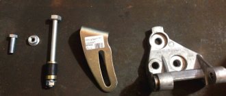
After unscrewing the fastening screws, remove the brush holder 2 with brushes. Unscrew the nuts of the coupling bolts 14 and remove the cover 11 of the generator along with the rotor. Clamp the rotor in a vice, unscrew the pulley fastening nut and remove the pulley from the rotor shaft with a puller 02.7823.9504.
The set of tool 67.7823.9504 includes a conventional puller and grip. The latter consists of two steel half-rings that are inserted into the pulley groove. The half rings have the same cross-section as the generator drive belt. On one side they are hinged, and on the other they are equipped with levers that are compressed by hand when removing the pulley.
Remove the segment key from the groove on the shaft and remove cover 11. Unscrew the nuts of the screws connecting the valve tips to the terminals of the stator winding, remove the neutral wire plug from block 4 and remove stator 8 from cover 16 of the generator. Unscrew the nut of the contact bolt 7 and remove the rectifier block 6 (or the radiator with positive valves).
Assembly . The generator is assembled in the reverse order of disassembly. The misalignment of the holes in the legs of the generator covers should be no more than 0.4 mm. Therefore, during assembly, a stepped cylindrical control mandrel is inserted into these holes, having a diameter of 12 mm on one side and 22 mm on the other. The conical spring washer of the pulley with its convex side should be in contact with the nut. The pulley nut is tightened to a torque of 38.4-88 N m.
Replacing the brush holder. If the brushes are worn out and protrude from the brush holder by less than 5 mm, then replace the brush holder with brushes. Before installing the brush holder, clean the installation area from coal dust and remove oil mixed with coal dust by wiping.
Replacing the rotor bearings on the drive side. To remove the faulty bearing from the cover, unscrew the nuts of the screws that tighten the bearing mounting washers, remove the washers with screws and press out the bearing using a hand press. If the nuts do not come off (the ends of the threads are open), then cut off the ends of the screws.
A new bearing is installed in the generator cover only if the bearing hole is not deformed. If the hole diameter is greater than 42 mm or it is deformed, the cover must be replaced. The bearing is pressed into the cover using a press and then clamped between two washers secured with screws and nuts. After tightening the nuts, the ends of the screws are opened.
Replacing valves. If a rectifier unit is installed on the generator, then if one of the valves fails, the entire rectifier unit is replaced. If the valves are in cover 16 and the radiator, then change the negative valves pressed into the cover. Positive valves pressed into the radiator cannot be replaced. If one or more positive valves are damaged, replace the radiator along with the valves.
The faulty negative valve is carefully pressed out using a press. Do not knock it out with a hammer, so as not to damage the hole for the valve and damage other serviceable valves pressed into the cover. The new valve is carefully, without distortion, pressed into the cover also on a press using a punch A.76028 and a support A.76031. It is strictly forbidden to press the valve in with hammer blows. The pressing force must act on the valve body, as shown in Fig.
The valves are pressed into the generator cover until the flange stops. For valves that have a non-knurled flange near the flange, a gap of 0.1 - 1.0 mm is allowed between the valve flange and the surface of the cover.
Top of page