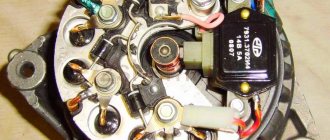
VAZ starter connection diagram
VAZ cars use starters, which are a DC electric motor with an electromagnetic two-winding traction relay and a roller freewheel clutch (overrunning clutch). Starters are used to provide the minimum crankshaft speed required to start the engine. The starter is powered in starting mode from the battery.
The starter relay is connected to the power circuit, thereby closing and opening the circuit, depending on how fast the crankshaft rotates. The starter design on all cars is the same, with only minor design differences. If you understand how the starter works in one car, you can easily figure it out in another.
To prevent a starter failure from taking you by surprise, let’s look at how to replace it yourself. But first, read the theory and study all the options for starter connection diagrams for different models of VAZ cars, collected by the editors of 2 Schemes.ru from familiar auto electricians.
Step-by-step connection of the starter on a VAZ-2110
The first step is to study how the starter works, because this is where any car begins its work. In addition, if you know how the starter works, you can start the engine and find out the reason for the poor start.
To repair a car starter yourself, you just need to know a few things.
Most drivers believe that the starter is a retractor relay. This relay changes the position in which the freewheel is located, which advances the gear to start the engine. When the engine starts, the relay is released from the current and the clutch returns to its previous position, thus moving the gear back. Due to this, the operating time of the gear is preserved, and the machine starter does not deteriorate.
The starter relay is connected to the power circuit, thereby closing and opening the circuit, depending on how fast the crankshaft rotates.
On all cars, the design of the starters is the same, the differences are only minor, which may be in the design, but not in the principle of operation. If you understand how the starter works in one car, you can easily figure it out in another.
Any starter has 40-60 main parts, these include:
- bendix;
- pull-in relay;
- DC motor electric.
VAZ 2101 starter connection diagram
- starter;
- holding winding of traction relay;
- ignition switch;
- generator VAZ 2101;
- fuse box;
- pull-in winding of the traction relay;
- accumulator battery.
Under normal loads, the current generated by the starter is 150 A. When heavy loads occur, for example in winter, the resulting current can reach 500 A. This is a serious test for this electrical unit, so it is not recommended to keep the key on the start for more than 10 seconds, and repeated starting attempts must be made with a break of at least a minute.
Starter connection diagram for 2105
- generator;
- accumulator battery;
- stator winding shunt coil;
- starter VAZ 2105;
- serial stator winding coil;
- holding winding of traction relay;
- pull-in winding of the traction relay;
- starter relay;
- mounting block;
- ignition switch.
VAZ 2106 starter connection diagram
- starter;
- generator;
- accumulator battery;
- pull-in winding of the traction relay;
- ignition switch;
- traction relay holding coil
| 1 – drive side cover; | 14 – relay cover; |
| 2 – retaining ring; | 15 – contact bolts; |
| 3 – restrictive ring; | 16 – collector; |
| 4 – drive gear; | 17 – brush; |
| 5 – overrunning clutch; | 18 – armature shaft bushing; |
| 6 – drive ring; | 19 – cover from the collector side; |
| 7 – rubber plug; | 20 – casing; |
| 8 – drive lever; | 21 – shunt coil of the stator winding; |
| 9 – relay anchor 2106; | 22 – body; |
| 10 – holding winding of the traction relay; | 23 – stator pole fastening screw; |
| 11 – pull-in winding of the traction relay; | 24 – anchor; |
| 12 – relay coupling bolt; | 25 – armature winding; |
| 13 – contact plate; | 26 – intermediate ring. |
VAZ 2110 starter circuit (5702.3708)
| 1 – drive shaft; | 20 – contact bolts; |
| 2 – front cover bushing; | 21 – output of “positive” brushes; |
| 3 – restrictive ring; | 22 – bracket; |
| 4 – gear with the inner ring of the overrunning clutch; | 23 – brush holder; |
| 5 – overrunning clutch roller; | 24 – “positive” brush; |
| 6 – drive shaft support with liner; | 25 – armature shaft; |
| 7 – planetary gear axis; | 26 – tie rod; |
| 8 – gasket; | 27 – back cover with bushing; |
| 9 – lever bracket; | 28 – collector; |
| 10 – drive lever; | 29 – body; |
| 11 – front cover; | 30 – permanent magnet; |
| 12 – relay anchor; | 31 – armature core; |
| 13 – holding winding; | 32 – armature shaft support with liner; |
| 14 – retractor winding; | 33 – planetary gear; |
| 15 – traction relay; | 34 – central (drive) gear; |
| 16 – traction relay rod; | 35 – carrier; |
| 17 – traction relay core; | 36 – gear with internal teeth; |
| 18 – contact plate; | 37 – layering ring; |
| 19 – traction relay cover; | 38 – hub with the outer ring of the overrunning clutch. |
Starter diagram VAZ 2108, 2109, 21099
Electric current enters the starter circuit from terminal “30” of the generator. Next, through block Ш8 (Х8) of the mounting block (pins 5,6), block Ш1 (Х1) - pink wire, to the ignition switch. The driver turns the key in the ignition to turn on the starter (position 2) and closes the contacts (50, 30). After which the ignition switch, through the red wire, current flows to block Ш1 (X1) of the mounting block (pin 8), then block Ш5 (Х5) (pin 4), starter switch relay (pin 85). The relay is activated. From terminal “30” of the start relay, current flows to terminal “50” of the starter traction relay, energizing its winding. The traction relay is activated, activating the starter.
The starter electrical circuit uses a switching relay 111.3747-10.
- Screw securing the protective cap.
- Protective cap.
- Retaining half ring.
- Rear cover fastening nut.
- Back cover.
- Brush springs.
- Brush guides (outer part).
- Brushes.
- Stator.
- Anchor.
- Drive lever.
- Drive unit.
- Restriction ring.
- Retaining ring.
- Drive lever axis.
- Screws for securing the traction relay.
- Front cover.
- Plastic sealing ring for the lid.
- Tie rods.
- Rubber plug.
- Traction relay core.
- Return spring.
- O-ring for traction relay.
- Traction relay.
- Sealing washer.
- Adjusting washers.
Starter circuit for VAZ 2110, 2111, 2112
Starters of type 57.3708 were installed on VAZ-2110 cars and had the following technical characteristics:
- Rated power 1.55 kW
- Current consumption at maximum power no more than 375 Amperes
- Current consumption in the inhibited state is no more than 700 Amperes
- Current consumption in idle mode no more than 80 Amperes
The connection diagram for the starter for the ten is shown above, here is its explanation:
- battery
- generator
- the starter itself
- egnition lock
| 1 – drive shaft; | 20 – contact bolts; |
| 2 – front cover bushing; | 21 – output of “positive” brushes; |
| 3 – restrictive ring; | 22 – bracket; |
| 4 – gear with the inner ring of the overrunning clutch; | 23 – brush holder; |
| 5 – overrunning clutch roller; | 24 – “positive” brush; |
| 6 – drive shaft support with liner; | 25 – armature shaft; |
| 7 – planetary gear axis; | 26 – tie rod; |
| 8 – gasket; | 27 – back cover with bushing; |
| 9 – lever bracket; | 28 – collector; |
| 10 – drive lever; | 29 – body; |
| 11 – front cover; | 30 – permanent magnet; |
| 12 – relay anchor; | 31 – armature core; |
| 13 – holding winding; | 32 – armature shaft support with liner; |
| 14 – retractor winding; | 33 – planetary gear; |
| 15 – traction relay; | 34 – central (drive) gear; |
| 16 – traction relay rod; | 35 – carrier; |
| 17 – traction relay core; | 36 – gear with internal teeth; |
| 18 – contact plate; | 37 – layering ring; |
| 19 – traction relay cover; | 38 – hub with the outer ring of the overrunning clutch. |
Electric sema VAZ 21102
| 1 — block headlight | 35 — instrument lighting switch |
| 2 - front brake pad wear sensors | 36 - ignition switch |
| 3 - reverse light switch | 37 - mounting block |
| 4 — electric motor of the engine cooling system fan | 38 - recirculation valve switch |
| 5 - sound signal | 39 — heater controller |
| 6 — gear motor for locking the right front door lock | 40 - hazard warning switch |
| 7 - power window relay | 41 — lamp illuminating the heater control levers |
| 8 - 8 A fuse | 42 — glove box lighting lamp |
| 9 - starter | 43 - glove compartment light switch |
| 10 - accumulator battery | 44 - cigarette lighter |
| 11 - generator | 45 — display unit of the on-board control system |
| 12 - windshield washer motor | 46 - ashtray lighting lamp |
| 13 — washer fluid level sensor | 47 — brake light switch |
| 14 — gear motor for locking the left front door lock | 48 — gear motor for locking the left rear door lock |
| 15 - left front door power window switch | 49 - left rear door power window switch |
| 16 — coolant level sensor | 50 — electric window motor of the left rear door |
| 17 - windshield wiper motor | 51 — socket for a portable lamp |
| 18 - recirculation valve | 52 - watch |
| 19 — micromotor gearbox for heater damper drive | 53 — electric window motor gearbox of the right rear door |
| 20 — electric heater motor | 54 — right rear door power window switch |
| 21 — trunk lock switch | 55 — gear motor for locking the right rear door lock |
| 22 - right front door power window switch | 56 - side turn signal |
| 23 — electric window motor reducer of the right front door | 57 - parking brake warning lamp switch |
| 24 — control unit for the door lock system | 58 — driver's seat belt sensor |
| 25 — additional resistor for the heater motor | 59 - directional lamp |
| 26 — brake fluid level sensor | 60 - interior lamp |
| 27 — electric window motor reducer of the left front door | 61 — cabin air temperature sensor |
| 28 - outdoor lighting switch | 62 — switch in the front door pillar |
| 29 — instrument cluster | 63 — switch in the rear door pillar |
| 30 - rear fog light switch | 64 — external rear light |
| 31 — fog light indicator lamp | 65 - internal rear light |
| 32 — indicator lamp for heated rear window | 66 — license plate lights |
| 33 — rear window heating switch | 67 - trunk light |
| 34 - Understeering's shifter |
A
— blocks for connecting the rear window washer motor.
B
- blocks for connecting the injection system harness.
C
- to the warning light harness block.
D
— block for connection to the on-board computer.
E
- to the headlight cleaner harness block.
F
— block for connection to the fuel level sensor in the electric fuel pump module.
G
- to the rear window heating element.
H
- block for connecting an additional brake signal.
J
- to the trunk lock motor.
The diagram does not conventionally show that in the instrument panel wiring harness, the second ends of all wires of white, black, orange, white with a red stripe and yellow with a blue stripe are connected to each other at the same points.
Connection diagram of the engine management system 2111 with distributed fuel injection of the VAZ-21102 car
- 1 – injectors 2 – spark plugs 3 – ignition module 4 – diagnostic block 5 – controller (since 2000, a modification of the system with M1.5.4N or “January-5.1” controllers has been produced) 6 – cooling system fan electric motor 7 – block attached to instrument panel wiring harness 8 – main relay 9 – fuse connected to the main relay 10 – electric fan relay 11 – fuse connected to the electric fan relay 12 – electric fuel pump relay 13 – fuse connected to the electric fuel pump relay 14 – mass air flow sensor
- 15 – throttle position sensor
- 16 – coolant temperature sensor
- 17 – CO potentiometer (not installed on vehicles with a modified control system, CO adjustment is carried out using the DST-2 device through the diagnostic block)
- 18 – idle speed regulator
- 19 – knock sensor
- 20 – crankshaft position sensor
- 21 – vehicle speed sensor
- 22 – immobilizer control unit
- 23 – immobilizer status indicator
- 24 – electric fuel pump with fuel level sensor
- 25 – oil pressure warning lamp sensor
- 26 – coolant temperature indicator sensor
- 27 – oil level sensor
- 28 – knock sensor (installed on vehicles with a modified control system)
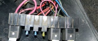
Fuse box VAZ-2110, VAZ-2111, VAZ-2112
F1 - 5A - License plate lamps. Instrument lighting lamps. Side light indicator lamp. Trunk light. Left side marker lamps. F2 - 7.5A - Left headlight (low beam). F3 - 10A - Left headlight (high beam). F4 - 10A - Right fog lamp. F5 - 30A - Electric door window motors. F6 - 15A - Portable lamp. F7 - 20A - Electric motor of the engine cooling system fan. Sound signal. F8 - 20A - Rear window heating element. Relay (contacts) for turning on the heated rear window. F9 - 20A - Recirculation valve. Windshield and headlight cleaners and washers. Relay (coil) for turning on the heated rear window. F10 - 20A - Reserve. F11 - 5A - Starboard side marker lamps. F12 - 7.5A - Right headlight (low beam). F13 - 10A - Right headlight (high beam). Indicator lamp for turning on the high beam. F14 - 10A - Left fog lamp. F15 - 20A - Electric seat heating. Locking the trunk lock. F16 - 10A - Relay-breaker for direction indicators and hazard warning lights (in emergency mode). Hazard warning lamp. F17 - 7.5A - Interior lighting lamp. Individual backlight lamp. Ignition switch illumination lamp. Brake light bulbs. Clock (trip computer). F18 - 25A - Glove box lighting lamp. Heater controller. Cigarette lighter. F19 - 10A - Door locking. Relay for monitoring the health of brake light lamps and side lights. Direction indicators with warning lamps. Reversing lamps. Generator excitation winding. On-board control system display unit. Instrument cluster. Clock (or trip computer). F20 - 7.5A - Rear fog lamps.
There are no fuses in the starting circuit.
Relay designation:
K1 – relay for monitoring the health of light bulbs; K2 – front wiper relay; K3 – repeater and alarm relay; K4 – low beam relay; K5 – high beam relay; K6 – additional relay; K7 – relay for turning on the heated rear window; K8 – backup relay (not installed on 110 series vehicles);
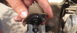
Starter solenoid relay
The starter relay is called a pull-in relay. This is due to the principle of its operation - it performs the function of connecting the starting device to the electrical circuit and connecting its armature to the crankshaft. It happens like this: when no current is supplied to the windings of the device, its armature, under the action of the return spring, remains in the forward position. The same spring, through a special fork, holds the Bendix gear, preventing it from engaging with the crankshaft flywheel ring.
By turning the key in the ignition, we supply current to the winding of the device. Under the influence of an electromagnetic field, the armature is fed back (pulled into the housing), closing the starter power contacts. The Bendix gear also moves, engaging with the flywheel. At the same moment, the retracting winding is turned off, and the holding winding comes into play. The force from the starter shaft is transmitted through the gear to the flywheel, causing the crankshaft to rotate until we no longer hold the ignition key in the start position.
What functions does the solenoid relay perform:
- Protects the starter from shorting contacts in the ignition.
- In order to turn off the power to the starter in a situation where the engine is running and the key shows the “starter” mode.
- Provides relief of contacts in the ignition switch.
When the engine starts, voltage from the generator goes to the relay coil. Then the gears of the drive system begin to work, due to which a magnetic field is created. The flywheel of the propulsion system is working. The gear begins its work thanks to the holding winding, while the bolts are closed. When the key is returned to the ignition switch, the winding is de-energized, thus disconnecting the gear and flywheel. This scheme applies to modern cars, including VAZ models.
If the starter makes a loud noise, the pole or starter could be loose. In the first situation, strengthen the fastening by tightening the screw, and in the second, secure the starter. If you disassemble the starter and see that the clutch is starting to slip, then the only thing you need to do is replace the starter drive.
Starter
Technical specifications
| Rated power, kW | 1,55 |
| Current consumption at maximum power, A | 375 |
| Current consumption in the inhibited state, A, no more | 700 |
| Current consumption at idle, A | 80 |
Starter 5702.3708
| 1 – drive shaft; 2 – front cover bushing; 3 – restrictive ring; 4 – gear with the inner ring of the overrunning clutch; 5 – overrunning clutch roller; 6 – drive shaft support with liner; 7 – planetary gear axis; 8 – gasket; 9 – lever bracket; 10 – drive lever; 11 – front cover; 12 – relay anchor; 13 – holding winding; 14 – retractor winding; 15 – traction relay; 16 – traction relay rod; 17 – traction relay core; 18 – contact plate; 19 – traction relay cover; | 20 – contact bolts; 21 – output of “positive” brushes; 22 – bracket; 23 – brush holder; 24 – “positive” brush; 25 – armature shaft; 26 – tie rod; 27 – back cover with bushing; 28 – collector; 29 – body; 30 – permanent magnet; 31 – armature core; 32 – armature shaft support with liner; 33 – planetary gear; 34 – central (drive) gear; 35 – carrier; 36 – gear with internal teeth; 37 – layering ring; 38 – hub with outer ring of overrunning clutch |
Starter 5702.3708 is installed on cars.
The vehicle can be equipped with an AZE2502 “Iskra” starter manufactured in Slovenia, which is similar in installation dimensions and technical characteristics. The parts of these starters are not interchangeable.
Starter type 5702.3708 is a DC electric motor with excitation from permanent magnets, with a planetary gearbox and an electromagnetic two-winding traction relay.
Lids 11
,
27
and the stator
29
are tightened with two studs.
The armature shaft 25
rotates in two metal-ceramic liners installed in the cover
27
and support
32
.
30
are fixed in the stator housing .
Rotation from the armature shaft 25
is transmitted to drive shaft
1
through a planetary gearbox, which consists of a central gear
34
, three planetary gears
33
, a carrier
35
and an
36
. Planetary gears rotate on needle bearings.
Starter connection diagram
| 1 – battery; 2 – generator; 3 – starter; 4 – ignition switch |
The starter connection diagram is shown in the figure. When the starter is turned on, voltage from the battery through the ignition switch is supplied to both windings of the starter traction relay (retractor 14
(see figure Starter 5702.3708) and holding
13
).
Under the influence of the magnetic field of the windings, the armature 12
of the relay is retracted and the lever
10
engages the gear
4
with the engine flywheel.
After closing the contact bolts 20
of the plate
18
, the retracting winding is turned off and the relay armature is held in the retracted state only by the holding winding.
When the key in the ignition switch (lock) is turned to position II, the holding winding is de-energized and the armature, under the action of the spring, returns to its original position, using lever 10
gear
4
from engagement with the flywheel.
Connecting wires to the starter
Connecting a starter to a VAZ - instructions. Attach the relay in a convenient place (for example, a washer reservoir). Connect the wires to the starter. Then remove the red wire located on the flat terminal of the relay, and you need to make a connection with the connector of the male wire and the wire from the new relay.
Place the wire with a ring terminal for 8 mm on the positive side of the starter and tighten it with a nut. Place the wire of the new “female” type relay onto the contact that was released at the traction relay. This wire will transmit the positive to the coil. Using a clamp, tighten the new wire and the stock one together. Screw a small length of wire from the coil. Now you can turn on the new relay.
Source
Structural features
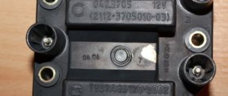
Drivers call a device such as a starter a starter, as it helps to start the car. It is practically no different from similar mechanisms. However, if you need to purchase a starter relay for a VAZ-2112, then you need to remove the part from the car and take the store with you. This element differs from similar ones in size. You can purchase a device from the VAZ-2111 or 2110 models, as it is completely identical.
On the twelfth model of the Zhiguli, the installed starter is of modest size. However, this small device is very functional. The technical documentation describes how the structure of the mechanism differs and where the VAZ-2112 starter relay is located. In the photo you can see the main and additional blocks.
Design and principle of operation
The VAZ 2110 starter does not have a very complex design, but a person who wants to repair this mechanism should know that its elements include:
- Drive shaft;
- Hubs with ring;
- Cover sleeve;
- Gears equipped with teeth and a coupling ring;
- Carrier;
- Drive shaft supports equipped with a liner;
- Anchor core.
- Gear axles are of the planetary variety.
- Permanent magnet;
- Gaskets;
- Frame;
- Collector;
- Lever bracket;
- Drive lever;
- The back cover is equipped with a special sleeve;
- Anchor relay and shaft;
- Holding winding;
- Brush holder;
- Traction relay core;
- Contact plate and bolts;
- Staples.
The starter components described most often require replacement, diagnosis or repair when problems occur.
Four devices creating a magnetic field are mounted to the starter housing. On the inside they are secured with an aluminum sleeve. The lid is tightly attached to the body. Reliable fixation is ensured thanks to two studs. The anchor shaft rotates in special bearings.
The starter plays a major role in starting the car, as it rotates the crankshaft
Through a planetary type gearbox, the torque “goes” to the drive shaft. Its transmission is ensured by a special gear. After the vehicle starts moving, it ensures their separation in order to protect the gearbox from damage.
When starting the engine, voltage is transmitted to two windings of the traction relay. After closing the contacts it stops working. The voltage should not exceed 8 V. If its value is higher or lower, then this “indicates” that there is a problem in the system.
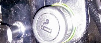
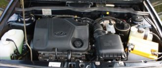
The starter on the VAZ 2110 is located to the left and slightly below the battery
Where is the VAZ 2110 starter relay located?
The solenoid relay is built inside the main body along with the starter itself. To dismantle, you need to follow the following algorithm:
- Determine the location of the starter itself. It is located to the left, just below the battery. You need to look for it in the immediate vicinity of the checkpoint.
- Disconnect the negative contact from the battery. This will help avoid troubles during dismantling (electric shock).
- Dismantle the air filter to free up the “passage” for further actions.
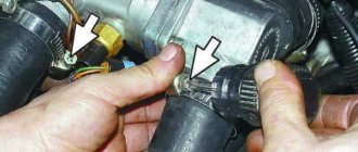
- Disconnect all wires that go to the relay.
- Dismantle the nut that serves as a fastener for the end of the wire. For this procedure you need a key of 13.
- Unscrew the nuts that focus the starter itself. To unscrew them, you need to use a 15mm wrench. The top one can be unscrewed without any noticeable problems, but to remove the bottom one, you will need to apply a noticeable force (it is located in an inconvenient place).
- Completely remove the starter.
- Remove the nut that secures the output of the relay that performs the retracting functions, and disconnect the wiring.
- Unscrew the bolts securing the relay (you need to use a wrench
 and remove it.
Node malfunctions
The most common starter breakdowns are divided into several types. These include:
- Damage to the electrical circuit. A sign of such problems is slow rotation or complete absence of it at the crankshaft when starting the internal combustion engine. The reasons for this phenomenon may be a discharge of the battery, rupture of the contacts of the ignition device, unreliable fixation, wear of the wires, or violation of the integrity of the wiring suitable for the relay contact group. If, when starting the internal combustion engine, the armature does not respond and the relay does not operate, then the cause of the failure is most likely due to a break in the solenoid relay wire. In the absence of the described “symptoms”, it is necessary to dismantle, check the plates for short circuits, and the presence of traces of “burning” in the collector system.
- Worn starter brushes. The presence of such problems may be indicated by difficulty starting the car, but not always. The reason for this phenomenon may be “hidden” in a battery failure. Complete wear of the brushes leads to the spring “resting” against the brush holder (contact is ensured only due to its mass). This can be easily checked by changing the position of the starter. The reason for premature wear is the misalignment of the brushes during the operation of the starter.
- Broken traction relay. This is indicated by a failure of the internal combustion engine, since it will not be possible to start the engine without a working relay. The “symptoms” of a malfunction of this starter element include its rapid rotation, even after starting the internal combustion engine, idling movement (without contact with the flywheel of the engine, which does not start), and a click after turning the key in the ignition device. It may not exist if there is a break in the coil, the armature is jammed, or there is no power for some reason.
- Lack of starter rotation with a characteristic “buzzing” sound. This phenomenon indicates the occurrence of a short circuit in the electrical circuit, in which power is supplied to the brushes of the electric motor. However, it is in working condition. In such a situation, the holding coil often does not work and the bendix does not move. Its gear cannot engage the flywheel gear, and the electric motor runs in idle mode. The reason may be that the force of the retracting element “enters” the bendix through a lever made of plastic (has the shape of a grip). If the movement resistance of the bendix is high, then the plastic elements break down. As a result, it is not moved to the working position and the starter rotates, but does not transmit torque to the flywheel. Another reason for the failure of the rotor can be severe wear of the teeth, which are located on the rotor shaft of the electric motor. Do not forget that complete destruction of the mentioned teeth can also cause failure. This type of malfunction is related to the breakdown of the motor and is not related to the functioning of the drive. The presence of such a breakdown is indicated by the activation of all starter mechanisms, that is, the rotation of the electric motor and the transition of the bendix to the working position. It can be locked by turning the key in the ignition.
Many car enthusiasts complain that the battery discharges quickly and cannot activate the starter. You can read about the reasons for battery discharge here: https://vazweb.ru/desyatka/elektrooborudovanie/razryazhaetsya-akkumulyator.html
The main malfunctions of the unit include: the appearance of oxide on the wires and terminals, failure of the traction relay and traction winding, wear of the brushes, breakage of the armature
The listed faults can cause more serious problems if they are not corrected in time. Ignoring problems will most likely lead to vehicle failure at the most inopportune moment. The best solution is to contact a specialized service station when the first signs of the listed problems appear.
DIY starter repair
Maintenance or repair of the starter must be carried out in accordance with certain algorithms, compliance with which requires certain experience and knowledge, as well as the use of the necessary tools. Troubleshooting always begins with disassembling the starter, after which diagnostics are carried out, and if problems are detected, repairs are carried out.
Tools and Supplies
To troubleshoot, you need to prepare the following tools:
- Socket heads for 13 and 15.
- Extension.
- Handle equipped with a ratchet.
- Ohmmeter.
- A special analyzer equipped with a light bulb.
- Phillips and flathead screwdrivers.
Spare parts will be used as consumables to replace failed components. You can determine which parts require replacement at the diagnostic stage described above. To repair the starter, it is recommended to use only high-quality parts.
How to remove and disassemble
To prepare for repairs, it is necessary to completely disassemble the starter. This procedure should be carried out in the following sequence:
- Remove the negative battery terminal.
- Remove the air filter housing to ensure convenience for further operations.
- Disconnect the wire leading to the traction relay.
- Place the disconnected wiring to the side so that it does not interfere with further repairs.
- Unscrew the nuts that secure the starter to the gearbox.
- Remove the unit and carry out further repairs in more convenient conditions.
- Disconnect the wire that is in contact with the mounting bolt.
- Remove the traction relay. To do this, you need to unscrew the two bolts that secure it.
- Remove the relay armature. To do this, you need to lift it up a little, and then remove the loop from the lever.
- Unscrew the nuts securing the tie rods.
- Remove the cover with the drive, as well as the gearbox assembly.
- Completely “remove” the tie rods. This will make it easier to further remove the drive and gearbox.
- Remove the planetary gears. They need to be replaced if there is damage to the teeth or the integrity of the needle bearings is compromised.
- Replace the brush holder assembly (if necessary).
- Remove the cover from the manifold side.
- Unscrew the two screws and then remove the brush holder from the cover.
- Bend the clips and remove the spring.
- Check the anchor for defects. To do this, you need to remove it from the case.
- Remove the gear from the anchor shaft.
- Remove the armature from the stator mechanism.
- Remove the sealing support from the lever.
- Knock the stopper off the retaining ring using a special mandrel.
- Dismantle the restrictor and retaining rings.
- Remove the drive assembly.
VAZ 2112 fuse diagram
With an 8-valve and 16-valve engine, it is equipped with a main mounting block, and since 2008 an additional console has been added. A diagram with element markings is printed on the left side of the main block cover and placed below.
The designations of all elements are presented below. You can find the transcript in the table.
| Circuit breakers | Power, A | What protects |
| F1 | 5 | Lamps for turning on the license plate lighting, instruments, side lights, trunk, left side. |
| F2 | 7,5 | Low beam |
| F3 | 10 | Further |
| F4 | 10 | PTF |
| F5 | 30 | Door windows |
| F6 | 15 | Portable lamp (socket) |
| F7 | 20 | Engine cooling fan. Sound signal. |
| F8 | 20 | Rear window heating element. Relay for turning on the heated rear window. |
| F9 | 20 | Recirculation valve. Cleaners, windshield and headlight washers (wiper fuse). Relay for turning on the heated rear window. |
| F10 | 20 | Spare |
| F11 | 5 | Starboard side marker lamps |
| F12 | 7,5 | Middle left |
| F13 | 10 | Far left. Power indicator lamp |
| F14 | 10 | Left PTF |
| F15 | 20 | Electrically heated seats. Trunk lock lock |
| F16 | 10 | Turn signals and emergency lights. |
| F17 | 7,5 | Interior lighting. Ignition switch. Stop signal. Watch. |
| F18 | 25 | Glove compartment lighting. Heater controller. Cigarette lighter fuse. |
| F19 | 10 | Locking door locks. Relay for monitoring the serviceability of brake light lamps and dimensions. Direction indicators. Reversing light. Generator excitation winding. On-board control system display unit. Instrument cluster. Watch. |
| F20 | 7,5 | Rear fog lamps. |
Relay
- K1 - lamp health monitoring;
- K2 - windshield wiper;
- KZ - direction indicators and emergency lights;
- K4 - switch on low beam;
- K5 - high beam;
- K6 - additional relay;
- K7 — heated rear window;
- K8 - rear PTF.
Starter fuse and relay
Installed on the device itself between the engine and the fan radiator. If signs of a malfunction appear, it is better not to delay replacing the element and install a new relay.
Fuel pump fuse and relay
Located in the additional interior installer - No. 3. Responsible for the fuel pump relay No. 5.
Relay and fuse for cigarette lighter
No. F18 is rated at 25 Amps.
Stove
The 25 A element F18 is responsible for protecting the operation of the electrical circuit of the heater motor.
Turn signals
The elements are marked as F19 and are rated at 10 Amps.
Brake lights
Located in the main block - No. F17. Its power is 7.5 A.
Where is the alarm fuse located?
No. F16 and rated 10 A.
Cooling Fan
The F7 element with a power of 20 Amperes is responsible for its protection.
Which fuse goes to the radio?
This is an F4 rated at 20 A.
Window lifters
F5 at 30 A.
Fuse and relay for central locking VAZ 2112: where is it located
They can be found in a separate box behind the main mounting block.
Ignition
The main relay is located in the additional cabin unit, where it is number 6.
Reverse
F19 with a rating of 10 Amperes is responsible for the lamps.
Fogs
Protected by three inserts: right - F4, left - F14, and rear - F20. The power of all PTFs is 10 Amps. In case of tuning, you may need to replace them with new ones along with the fog lights. The connection occurs via switch K8.
Lamp health monitoring relay
Marked as K1 in the main block of the VAZ 2112.
Brake
Installed under the brake pedal.
Relay and fuse for injectors
The additional element F3 is rated at 15 Amps.
Fuse for interior light
The F17 element with a power of 7.5 A is responsible for the safe operation of the VAZ 2112 interior lighting lamp.
Number plate illumination
Corresponds to F1 with a rating of 5 Amps.
Generator
A three-level relay voltage regulator is located on the device. It is better to replace the factory element with a new one, since three-level voltage regulation often leads to a short circuit.
Heated rear window
Relay K7 is responsible for turning on. Protects the F8 electrical circuit with a rating of 20 Amps.
Seat heating
It is protected by a 20 Amp F15 insert.
Wiper relay
This is a K2 and without its stable operation there will be no washer supply to the windshield, and the wipers will not be able to do their job.
Charger
They placed it next to the device - one of the few elements of this kind under the hood of a car.
Low and high beam VAZ 2112
It is protected by fuses F2 and F12 (left and right headlights), and the high beam is protected by F3 and F13 (left and right). The first has a rating of 7.5 A, and the second has a rating of 10 A.
Fuse for the dashboard of VAZ 2112
Located in the wiring harness leading to the instrument panel from the battery.
Dimensions
There are 2 fusible elements - F1 and F11, left and right. The power of both is 5 Amperes. Factory fuses require replacement due to the fact that the dimensions often burn out due to their malfunctions.
Heated seats
It is protected by an element marked F15 for 20 Amperes.
VAZ 2112 speedometer fuse: where is it located?
He's gone.
Opening the trunk
This is an F1 and is rated at 5A.
Fuse F6
Responsible for protection against burnout of the car socket. Its rating is 15 Amperes.
VAZ 2112: fuse F17 blows
Most often, this element, which is responsible for interior lighting, fails due to a battery failure. Its power is 7.5 A.
Fuse F19
Responsible for protecting the brake light, reversing lights and dimensions.
Relay K1
An element of lamp serviceability, which in older versions is replaced by a jumper.
Relay K6
This is a reserve item.
Speed sensor
Located on the wiring harness leading to the device.