From 1987 to 2008, the domestic auto industry produced a particularly small class car with the designation VAZ-1111 (1113) and the name “Oka”. It was a rather interesting model of a small city car, which was initially positioned as a car for the disabled.
The car was interesting for a number of factors:
- The smallest car of the Volzhsky Automobile Plant (although it was also produced by SeaZ and KamAZ);
- At one time it was the cheapest car in the world;
- Its own engine was developed for it, and not simply borrowed from other models;
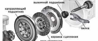
As for the power plant, the Oka is the only domestic car equipped with a two-cylinder unit, which is structurally complete and modern - with a liquid cooling system, a timing belt drive, and a transverse arrangement.
Naturally, when designing this unit, we followed the usual path - maximum unification with other VAZ engines, but still it was a separate engine, with its own characteristics. Note that almost everywhere the unification of components was used, which made it possible to reduce the cost of car production as much as possible.
Engine modifications
A few words about the engines of this car. Initially, the Oka was equipped with a unit with a working volume of only 650 cubic meters. cm. The basis for its creation was the installation from the VAZ-2108 with a 1.3-liter unit, but the number of cylinders was reduced to two (people often said that the Oka uses half of the G8 engine). The model with this engine received the factory index VAZ-1111.
A little later, another modification began to be produced - the VAZ-1113, whose volume was increased to 750 cubic meters. see, but in fact, they “halved” the 1.5-liter unit of the same “Eight”. Naturally, the engine power indicators also changed. For the 650 cc engine this figure was 29.3 liters. s., and for 0.75 liters - 33 liters. With.
The VAZ-1113 modification was the most widespread, so we will consider it in the future. We also note that in the last years of production, the Oka was equipped with a 1.0-liter Chinese engine with 3 cylinders, but there were few of them.
Oka was brought from Kazan for major repairs. The power unit required an integrated approach - the cylinder block, gearbox and cylinder head needed repair. Indicators for transmission repair are a crunching sound when engaging second gear. The block suffered from uneven compression across the cylinders (diagnostics showed that the problem was in the piston group of the first cylinder). As for the head, it was decided to carry out a complete modification and install the highest shaft from the tuning series DynaCAMS RS. First of all, we removed the VSV (external speed characteristic) from the production engine using the “Dynamic Motor Tester”. We will compare the results of engine development with it.The head assembly was removed. Instead, a modified one will be installed from the replacement stock (it was already prepared by the time the machine arrived, which significantly saved the overall time of working with the machine). The previous owners used low quality engine oil - probably mineral water, since the inside of the engine is heavily covered with black deposits. The box was filled with an unknown light brown slop.
We dismantle the cylinder block assembly from the car, then remove the gearbox.
During the repair of the gearbox, the following were replaced: all synchronizers (4 pieces), 1st-2nd gear synchronizer clutch, 2nd gear gear, intermediate reverse gear, all oil seals, rocker shaft drive. The gear selector forks were in good condition and did not require replacement.
Next we disassemble the cylinder block. It turns out that a bolt is stuck in the oil receiver, and another one was found in the crankcase. Someone dropped it into the engine... Inspection of the removed pistons and connecting rods showed that the piston skirts and rings were worn out. Again, attention is drawn to a large amount of soot and deposits, especially in the oil scraper rings. With high-quality oil, oil scraper rings never become clogged with deposits. The low quality of the oil used also results in an abundance of yellow varnish deposits on the block parts.
The old balance shaft gears (plastic) are still in good condition, but they are changed preventively so that there are no problems with them in the future operation of the motor. The crankshaft did not require grinding to repair size, but only underwent cleaning and purging of the oil channels. The photographs show old liners - in this year's engine, some of the liners no longer have grooves, but only holes.
After complete disassembly, the block was bored and honed to a repair size of 82.4 mm. For the engine, pistons were purchased - 1st repair, serial VAZ ones, piston rings - 21083 (1st repair) produced by STK (Samara Technological Company). After boring and honing, the block was thoroughly washed. In the process of discussing the scope of work with the owner of the car, it was proposed to install oil nozzles for cooling the pistons from the car 2112. In the block of this car, special nozzles are pressed into the main supports of the crankshaft, which supply oil to the piston bottoms. The injectors are equipped with a ball valve that prevents oil from draining from the supports when the engine is stopped. The injector operating mode is constant. The advantages of such injectors are invaluable - by cooling the pistons with oil, their overheating and hot ignition (dieseling) are prevented, in addition, detonation is reduced (a huge plus when accidentally filling with bad fuel). The risk of piston burnout and thermal jamming of rings is significantly reduced. In addition to the piston crown, oil also reaches the cylinder walls, significantly reducing wear on the cylinders, rings and the piston itself. To summarize, we can say the following - injectors significantly increase engine life. However, such injectors were never installed on Oka cars, as well as on all front-wheel drive VAZ cars, except for 16-valve 2112 cars.
For installation in the 11113 block, the injectors were modified, and holes with a step were drilled in the main supports for reliable fixation of the injectors. The injectors are installed in the outer crankshaft supports, since the middle crankshaft journal is the most loaded. The nozzles are installed in supports with tension, using a special one-piece sealant for threaded connections for reliable fixation.
The direction of the oil nozzle is selected in such a way that the oil falls on the part of the piston bottom that is distant from the spark plug.
When assembling the engine, both oil seals were replaced, crankshaft and connecting rod bearings were used produced by ZMZ brand “Double Resource”, plastic ball joints (balance shaft gears) were installed.
The photo below shows the assembled unit, prepared for installation in the engine compartment.
The consumable fluids and materials used are of high quality - the box is filled with semi-synthetic Valvolin, the cooling system is filled with Nord antifreeze, and the engine is filled with Lukoil Lux 5W40 semi-synthetic oil for the break-in period (2000 km). This oil is the optimal and proven choice for this engine - it combines high detergency and excellent wear protection.
The box, and then the engine, are installed in place. At the same time, we change the tension roller and timing belt.
Next it was the turn to install the modified head. The list of improvements and changes is as follows: lightweight T-shaped valves, bored and ground channels in the head and manifold, modified combustion chambers, slightly increased compression ratio. The guide bushings are cast iron, manufactured by STK . The camshaft is installed DynaCAMS RS628 with an intake valve lift 11.5 mm ( OKB Dvigatel ).
The shape of the combustion chamber is chosen to be flat and partially made on a milling machine. The bottom of the chamber was lowered flush with the seats, the area around the spark plug was refined, excess meat around the valves was removed and the surface was sanded. This form of combustion chamber allows for increased torque at low speeds, but has slightly worse knock resistance than other forms of chambers being tested in parallel, however, piston cooling nozzles completely neutralize this feature.
The carburetor has been reconfigured. The car is equipped with a Pekar plunger fuel pump, famous for its reliability and reliability. Before starting the engine for the first time, engine oil and antifreeze are heated with a heat gun, and only then added. This makes it easier to start the engine for the first time and allows oil to fill the oil system faster.
After starting the engine, all systems were adjusted. This was followed by an initial run-in and the engine was sent for removal.
So, let’s evaluate the results of our work (click on the screenshots to view):
| OKA 11113 serial car engine without an air filter. Engine power 33 hp, torque 5.6 kg (for comparison, the serial 21083 has 11.4 kg) . The measurement was made up to 6500 rpm. |
| VSKh engine of the OKA 11113 after overhaul with a DynaCAMS RS628 and a modified cylinder head. Measurement without air filter. The car now has a peak power of 39 hp. ( +6 hp, 19% increase). The maximum torque in absolute terms has not increased ( 5.5 kg). |
A very interesting section in the range from 1500 to 3000 rpm. There is a fairly noticeable increase in torque and power. This is the range of leisurely and quiet city driving, when you need to leisurely drive in city traffic without turning the engine. Accordingly, during quiet operation in this range the engine will be quite torquey and economical. In the range of 3000-4800 rpm, a decrease in torque and, accordingly, power is observed. Further along the revolutions, the top shaft shows its true essence - a powerful “ pickup ” begins, which is distinguished by all owners of RS628 shafts - the power and torque curves soar upward. At 6000 rpm, the gasping production engine produces only 28 hp. and 3.3 kg of torque, and on the modified version - 36.4 hp. (increase +8.4 hp or 29%!!! ) and 4.3 kg of torque (increase +1.0 kg, 29%!! ). In conclusion, the following can be said about the results of removing the VSH - the result is an interesting motor that combines excellent lows (which is very unusual for a top shaft) and powerful highs. Peak power has increased by 19% , but the increase in torque and power at high speeds ( 6000 rpm ) is an impressive 29% . The engine operating range is from low to 7500 rpm. Moreover, as the engine runs in, power and torque at high speeds will increase even more, since mechanical losses will decrease.
All that remains is to wish its owner successful and long-term operation of the car!
Work on the car was completed in January 2008. The article was written: February 4, 2008. Author of the article, photo-video materials: © Quasar The following are prohibited without the written permission of the author: reprinting the article in whole or in part, reprinting and use of photo-video materials, as well as changing and editing them for further publication on third-party sites.
Features of repair and maintenance
Like any internal combustion power plant, the VAZ-1113 engine required periodic maintenance, and after its service life was exhausted, a major overhaul was carried out or a complete replacement of the engine on the Oka.
Despite the fact that the service life of the OKA engine is approximately 1.5-2 times less than that of standard VAZ models.
Overhaul of the Oka engine is carried out in case of severe wear of the cylinder-piston group and the crank mechanism. Moreover, although the engine life is approximately calculated by the manufacturers, it is greatly influenced by the characteristics of operation, the frequency of maintenance, as well as the quality of the technical fluids and fuel used.
In most cases, Oka engine repairs are performed without removing it from the car. In a number of systems and mechanisms, it is possible to remove components from the power plant for subsequent restoration or replacement, or even do everything on the unit. This applies to power systems, ignition, starting, electrical supply, cooling, as well as the gas distribution mechanism.
But removing the motor and disassembling it will be necessary if it concerns the cylinder-piston group and the crank mechanism, which includes the balance shaft system. As for the latter, they are a design feature of the two-cylinder engine.
The fact is that the pistons in Oka installations move in pairs, not separately. But at the same time, the power strokes in the cylinders are performed differently. For example, both pistons move upward, but in the first cylinder there is a compression stroke, and in the second - an exhaust stroke. After passing through the VTM, the first cylinder has a working stroke, and the second one has an intake stroke, and so on in a circle.
The balancing system prevents the occurrence of increased vibrations, which necessarily arise with such design and operation features of the power plant.
If the power unit has exhausted its resource, that is, the wear of the cylinder-piston group has reached critical values, or a serious breakdown of the crankshaft has occurred, the engine is overhauled. In this case, all work can be performed only on a removed installation.
Next, we’ll look at how to properly remove the power plant from the engine compartment of this car with your own hands, without resorting to the services of a service station.
Installing a carburetor on the Oka
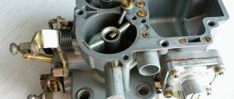
Reinstalling the carburetor mechanism on a vehicle after cleaning and repair can be a labor-intensive procedure. In order for the power unit to operate in normal mode, it is necessary to correctly connect all the components of the carburetor and securely fix them.
Getting started with installing the DAAZ-1111 is based on installing the gasket. The element is put on the studs and pressed tightly against the surface of the intake manifold. After which the carburetor itself is installed in its place:
First, screw in the two fastening nuts on the front side.
The other two nuts are tightened on the back side, after which the economizer valve can be returned to its previous position.
The first step is to connect the pipe that supplies fuel to the mechanism. It is recommended to use a new clamp to secure it.
Next, connect the vacuum regulator hose.
The connector that comes from the engine is connected to the forced idle economizer valve. Before connecting, it is advisable to make sure that the connector is clean and free of deformations.
The crankcase ventilation hose is connected to the fitting.
The tip of the intermediate rod of the lever is screwed to the corresponding place on the carburetor.
The drive rod is returned to its place and connected to the lines.
Next, it is recommended to install the air filter in place and check the operation of the system. If gasoline leaks out at the joints, you need to carefully tighten them again.
It is recommended to carry out all work in natural light or good artificial light
What you need
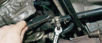
The main key points will be shown in the photo. Let us immediately note that there are several ways to remove the motor, and one of them involves the presence of lifting mechanisms (hoists), which not everyone has, so we will consider another method, with removing the power plant through the bottom of the car.
To carry out the work you will not need much:
- Sets of wrenches (open-end, spanner), as well as heads with knobs and rods;
- A set of screwdrivers (flat, Phillips, reinforced, etc.);
- Jack (2 pcs.);
- Wooden beams;
- Rags;
- Containers for draining technical fluids;
How to remove
The removal procedure is quite simple, but it is recommended to follow a clear action plan so as not to damage the internal components of the carburetor during the dismantling process. To successfully carry out the work, you will need only three tools:
open-end wrench 8;
open-end wrench 13;
Before starting work, you must disconnect the wire from the negative terminal of the battery. This action will protect you from possible electric shock.
The procedure for dismantling the DAAZ-1111 carburetor is as follows:
It will be necessary to remove the air filter box. It is located in such a way that it prevents free access to the carburetor.
After this, you will need to loosen the bolted connection securing the damper drive rod to the lever. You will also have to slightly unscrew the bolt that secures the damper drive to the bracket.
After loosening, the bolts can be easily unscrewed - you need to disconnect the drive rod from all connections.
Using a screwdriver, disconnect the intermediate rod end from the lever.
Next, you need to disconnect the crankcase ventilation hose, which is connected to the fitting.
Afterwards, you can safely remove the wiring from the economizer valve.
The next step is to disconnect the vacuum regulator hose.
Next, you will need to loosen the clamp on the fuel supply pipe and remove the hose. Some fuel may spill out.
After which you can begin the procedure of removing the carburetor body. To do this, you will need to unscrew the forced idle economizer valve; behind them there are two nuts that need to be unscrewed.
After removing the filter element bracket, you can unscrew the two nuts that are located on the front side of the carburetor.
The device is carefully removed from the studs.
The main thing is to follow the exact procedure
Immediately after dismantling the carburetor, it is recommended to block the resulting hole in the intake manifold with a lint-free cloth. This measure is necessary to ensure that dust and dirt do not get inside.
Cleaning carburetor elements from carbon deposits and dirt
It is advisable to have the carburetor cleaned both outside and inside at a service station. However, if the car owner has experience in independently servicing his car, then it is allowed to clean the carburetor from carbon deposits with his own hands. However, you should be as careful as possible, since some parts of the mechanism require special care.
Powerplant removal method
The sequence of work is as follows:
- We put the car in the garage and immobilize it. For the convenience of carrying out some work, we jack up the front end, completely, and not just one side;
- drain technical fluids (oil, coolant);
- We dismantle the carburetor air filter along with the housing;
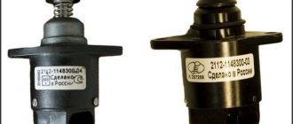
- Disconnect the throttle and air damper drive cables from the carburetor, as well as the XX solenoid valve wire;
5. Remove the high-voltage wires (from the spark plugs and coil);
6. Disconnect the wiring going to the spark torque sensor;
7. Loosen the clamp securing the gasoline supply pipe to the gasoline pump and remove it;
9. Loosen the clamps and remove the pipes from the thermostat housing that go to the cooling radiator;
10. Remove the pipes leading to the interior heater;
11. Loosen and disconnect the clutch cable;
12. From the gearbox, disconnect the speedometer drive, the wire of the sensor for turning on the reverse signal, as well as the ground wire put on the stud of the gearbox housing;
13. Disconnect the wiring from the starter and generator;
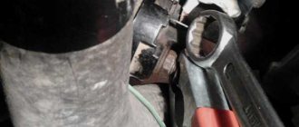
14. Under the car, loosen the tie clamp at the entry point of the exhaust pipe coming from the manifold into the receiving pipe of the resonator. We move the resonator back, disconnecting the connection;
15. Disconnect the wire leading to the oil pressure sensor;
16. Disconnect the gearshift lever rod leading to the gearbox;
17. Remove the front wheels, unscrew the nuts of the outer CV joint shafts, and pull the hubs off them;
18. Unscrew the bolts securing the steering gear brackets to the subframe;
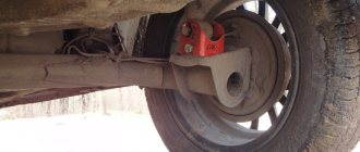
19. We place the prepared bars under the subframe, after which we carefully lower the jacks, ensuring that the subframe, together with the engine, rests on these bars;
20. Unscrew the bolts securing the subframe to the body;
After this, it is checked whether everything is disconnected, and then, with an assistant, the front end simply rises up (without the motor - it is not heavy) and the body rolls back, and the motor, together with the gearbox, the drive and the subframe, remains lying on the bars.
Well, then further disassembly is carried out, the worn components are rebuilt (for example, replacing the Oka crankshaft), and then the engine is assembled. After the VAZ-11113 engine has been repaired, it is reinstalled in place, for which everything must be done in the reverse order.
What can be repaired with the engine removed?
The described method is one of the easiest to perform, since it does not require any special equipment.
Now let’s go over why you should remove the internal combustion engine from a car at all, and what kind of repairs can be done. As already noted, dismantling is carried out in the event of a replacement of the power plant, as well as problems with the crankshaft and CPG.
One of the frequently performed works is replacing the rings on the Oka. This operation is difficult because it requires almost complete disassembly of the engine to remove the pistons. And it is naturally easier to disassemble it if it is installed on a table or floor, and you can easily turn it as convenient.
Also, all work with the crankshaft is carried out on the removed engine, because removing and installing the crankshaft without dismantling the gearbox is impossible, and while the installation is on the car, the gearbox is practically impossible to remove.
But we note that removing the engine to carry out work on the cylinder-piston group and the crankshaft is a recommendation from the manufacturer. If the matter concerns only the cylinder-piston group (for example, replacement of piston rings or pistons is required) and grooving of the cylinders is not expected, then all work can be performed without removing the engine.
Let's look at how to replace the same rings on an Oka engine without removing it from the car. The tools you will need are the same as those listed above, but it is best to perform the work in the inspection hole.
How to choose rings and pistons
Let's go through how to choose replacement rings. Everything is relatively simple here. When creating this engine, the designers tried to unify it as much as possible with another, namely the VAZ-2108. Therefore, the dimensions of the Oka pistons are completely identical to the Vosmerov pistons, only their number is different. In this case, you should focus on the engine size. To modify the VAZ-1111 with a 0.65-liter engine, rings from a 1.3-liter engine are suitable, since the piston diameter of the Oka and the V8 are identical. The same applies to another model - VAZ-1113 with a 750 cc engine. cm. Rings and pistons from a 1.5-liter engine of the same VAZ-2108 are suitable for it.
When selecting, you should also take into account that when replacing, pistons and rings of repair sizes are used. In addition, configurations of the same rings specifically for Oka are practically not found, so you will have to purchase a complete set for the VAZ-2108, but use only half of it.
Sequencing
Let's move on directly to the process of replacing piston rings on a VAZ Oka without removing the engine (key points are shown in the photo). Everything is done like this:
- The car is placed on a viewing hole and immobilized;
- Working fluids (coolant, oil) are drained;
- The first stage of work takes place entirely in the engine compartment. For ease of work, you can completely remove the hood from the car;
- We remove the air filter housing from the carburetor, disconnect the drive cables, the XX solenoid valve wire and the gasoline pipelines;
5. Remove the protective cover of the timing drive, loosen the drive roller, and remove the belt from the camshaft gear. We unscrew the bolt of this wheel and remove it from the shaft (carefully so as not to lose the key);
6. Disconnect the pipes from the valve cover, unscrew the bolts securing it and remove it from the car;
7. Disconnect the vacuum regulator pipe;
8. Unscrew the bolts securing the spark torque sensor and move it to the side;
9. Unscrew the fuel pump and put it aside;
10. Unscrew the fastening of the spark torque sensor drive housing and remove it;
11. Unscrew the upper bolt securing the rear timing belt cover and move it to the side;
12. Unscrew the nuts securing the camshaft bearing housing and remove it;
13. Carefully dismantle the camshaft along with the oil seal. When assembling, it is better to replace the Oka camshaft oil seal. If you are only replacing the camshaft on the Oka, further disassembly is not necessary;
14. Remove the generator mounting bracket;
15. Remove the tension roller;
16. Disconnect the cooling system pipelines leading to the cooling jacket;
17. Disconnect the wire of the coolant temperature sensor;
18. Unscrew the nuts securing the exhaust pipes from the head, then carefully remove them from the studs;
19. Unscrew the head mounting bolts. In this case, you need to follow the correct sequence of their relaxation. Remove the bolts;
20. Carefully remove the head along with the intake manifold and carburetor.
This concludes the disassembly in the engine compartment. The rest is done under the car. To remove the pistons, you must:
- Unscrew the engine sump mounting bolts and carefully remove it;
- Unscrew the nuts securing the connecting rod caps and remove them. It is important to immediately mark where each cover is and how it was installed. To do this, marks can be placed on the low tide by punching;
- We turn the crankshaft. At the same time, the pistons will come up, and the connecting rods will be removed from the shaft journals. All that remains is to use a screwdriver to completely push out the pistons along with the connecting rods and remove them.
After replacing the rings, using a special device for seating the pistons, we put them in place, trying to immediately guide and place the connecting rods correctly (you can ask an assistant to guide them from below). And then all the removed elements are simply installed in place.
"Oka" 1111/11113 operating, maintenance and repair manual
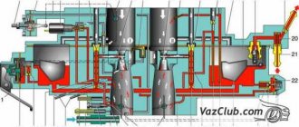
VAZ-1111 Oka cars and their modifications are front-engine, with a transverse engine, front-wheel drive, four-seater. The body is two-volume, load-bearing structure, all-metal, welded. Engines - two-cylinder, in-line, four-stroke, carburetor, volume 0.65 l (currently not produced) and 0.75 l, power according to GOST 14846-81 (net) from 25.9 to 33.0 hp. Engines of the VAZ-1110 model were produced in a small batch. The cars were produced by the Kamsky (KAMAZ) and Serpukhov (SeAZ) automobile plants. Currently, the production of Oka cars remains only at the Serpukhov Automobile Plant, which also produces modifications for the disabled. The vehicle model and number, engine model and spare parts number are indicated on the nameplate attached to the upper cross member of the radiator frame. Ignition system Spark torque sensor: 1 - front roller bearing holder; 2 — sensor support plate; 3 — screen; 4 — spring weight of the centrifugal regulator; 5 — regulator weight, 6 — driving plate of the centrifugal regulator; 7- oil seal; 8 — roller; 9 — coupling; 10 — bushing of the rear end of the roller; 11 — driven plate of the centrifugal regulator; 12 — vacuum regulator; 13 — fitting for supplying vacuum; 14 - thrust; 15 — contactless sensor (Hall sensor); 16 — body; 17 — Hall sensor wiring block; 18 - cover; a - diagram of the operation of the centrifugal regulator; ἁ — ignition timing angle. Details of the spark torque sensor: 1 - coupling; 2 - body; 3 — vacuum ignition timing regulator; 4 - oil seal; 5 - non-contact sensor (Hall sensor); 6 — driving plate of the centrifugal regulator; 7 — weight of the centrifugal regulator; 8 — drive plate roller; 9 - spring; 10 — driven plate of the centrifugal regulator with a screen; 11 — lock washer; 12 — sensor support plate with bearing; 13 — bearing lock plate; 14 — front bearing holder; 15 - cover. The ignition system is contactless. Consists of a spark torque sensor, switch, ignition coil, spark plugs, ignition switch and high and low voltage wires. Spark timing sensor - type 5520.3706 (until 1989, a type 55.3706 sensor was installed) with built-in vacuum and centrifugal ignition timing regulators. It sets the moment of spark formation depending on its initial setting, the number of revolutions of the crankshaft and the load on the engine. Reading of control pulses is based on the Hall effect. There is one pulse for each revolution of the crankshaft (two for each revolution of the camshaft). The initial ignition timing angle for the VAZ-1111 engine is 1±1° before TDC, for the VAZ-11113 it is 4±1° before TDC. You can check the functionality of the Hall sensor with a voltmeter by connecting it between the terminals of the green and white-black wires. Slowly rotating the spark sensor shaft, we monitor the voltmeter readings. The voltage should change sharply from the minimum (no more than 0.4 V) to the maximum (no more than 3 V less than the supply voltage). If a steel screen with slots touches the sensor (determined by slight jamming or a scratching sound when the roller rotates, as well as after partial disassembly of the spark torque sensor), check the axial play of the roller (no more than 0.35 mm, adjusted by selecting washers) and the fit of the screen on roller If necessary, replace the assembly. A faulty Hall sensor cannot be repaired and must be replaced with a new one (with the exception of a broken wire between the sensor itself and the block on the spark torque sensor housing). You can roughly assess the serviceability of the vacuum regulator directly on the car. With the engine running, disconnect the vacuum hose leading to the regulator from the carburetor fitting. If you now create a vacuum in the hose (you can use your mouth), the engine speed should increase, and when the vacuum is removed, it should decrease again. The vacuum should remain for at least a few seconds if the hose is pinched. You can visually verify the functionality of the vacuum regulator by partially disassembling the spark torque sensor (see “Removing and disassembling the spark torque sensor,” p. 86) and applying a vacuum to the inlet fitting of the regulator. In this case, the screen of the spark torque sensor should rotate at an angle of 10±1°, and when the vacuum is removed, return back without jamming. Accurate testing and adjustment of vacuum and centrifugal ignition timing regulators is carried out on special stands. It is not recommended to do this at home. If the vacuum regulator fails, it is replaced; if the centrifugal regulator fails, the spark torque sensor is replaced.
A switch type 3620.3734, or 36.3734, or HIM-52 opens the power supply circuit of the primary winding of the ignition coil, converting the sensor control pulses into current pulses in the ignition coil. The switch is checked with an oscilloscope using a special method; if a malfunction is suspected (interruptions in engine operation, shots in the muffler), replace it with a known good one. Do not disconnect the switch connector while the ignition is on - this may damage it (as well as other components of the ignition system). Ignition coil - two-output, dry, type 29.3705 - with an open magnetic circuit, or type 3012.3705 - with a closed magnetic circuit. Data for testing: resistance of the primary winding at 25 ° C - (0.5 ± 0.05) Ohm, secondary - (11 ± 1.5) kOhm. The insulation resistance to ground is at least 50 MOhm. Spark plugs - type A17DVR, or A17DVRM, or their imported analogues (with noise suppression resistors with a resistance of 4-10 kOhm). The gap between the electrodes should be within 0.7-0.8 mm (checked with a round wire probe).
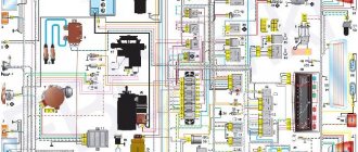
High-voltage wires - type PVVP-8 with distributed resistance (2000±200) Ohm/m or PVPPV-40 with distributed resistance (2550±270) Ohm/m. Do not touch high-voltage wires while the engine is running - this may result in electrical injury. It is also prohibited to start the engine or allow it to operate with an open high-voltage circuit (removed wires) - this can lead to insulation burnout and failure of the electronic components of the ignition system. Ignition switch type 2108-3704005-40 or KZ813 with anti-theft locking device, blocking against restarting the starter without first turning off the ignition. When the key is turned to the “ignition” position, voltage is applied to the control input of an additional relay type 113.3747-10, which, in turn, supplies voltage to the ignition coil and switch. Thus, the contacts of the ignition switch are relieved (see also “Electrical equipment”). Diagram of a non-contact ignition system: 1 - ignition switch relay; 2 — ignition switch; 3 - fuse block; 4 - switch; 5—sparking moment sensor; 6 — ignition coil; 7 - spark plugs.
A book in a series of full-color illustrated guides to do-it-yourself car repairs. The manual describes the design features of components and systems of Oka VAZ-1111, -11113 vehicles, as well as their modifications for disabled drivers. The main malfunctions, their causes and solutions are described in detail. The disassembly and repair processes are illustrated and annotated. A separate section is devoted to car care. The Appendices present tools, lubricants and operating fluids, lip seals, bearings, tightening torques for threaded connections, as well as a diagram of electrical equipment. The book is intended for drivers who want to repair a car themselves, as well as for service station workers.
Assembly Features
Important points during assembly:
- During the assembly process, it is imperative to replace the gaskets of the cylinder head, sump, exhaust pipes, and valve cover;
- Tighten the block head bolts in a strictly defined sequence;
- After assembly, perform the adjustment correctly - align the marks of the crankshaft and camshaft to ensure proper operation of the timing belt, tighten the drive belts, check the thermal clearances;
And although there are quite a lot of operations that need to be performed to remove the motor or replace the rings, they are not complicated and all the work can be completed in a day.