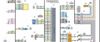
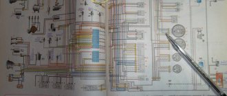
General wiring diagram
- Headlights;
- Front direction indicators;
- Electric fan activation sensor;
- Sound signal;
- Electric engine cooling fan;
- Side direction indicators;
- New formation moment sensor;
- Spark plug;
- Ignition coil;
- Windshield washer pump motor;
- Accumulator battery;
- Generator;
- Oil pressure warning light sensor;
- Carburetor solenoid valve;
- Coolant temperature sensor;
- Reversing light switch;
- Switch;
- Plug socket for portable lamp;
- Brake fluid level sensor;
- Starter;
- Windshield wiper motor;
- Relay-breaker for direction indicators and hazard warning lights;
- Headlight high beam relay;
- Relay for low beam headlights;
- Starter activation relay;
- Electric fan switch relay;
- Fuse box;
- Parking brake warning light relay;
- Windshield wiper relay;
- Rear window wiper and washer switch;
- Rear window heating switch;
- Rear fog lamp switch;
- Carburetor choke warning lamp switch;
- Fog light circuit fuse;
- Carburetor air damper warning lamp;
- Hazard switch;
- External lighting switch;
- Heated rear window relay;
- Heater fan motor switch;
- Brake light switch;
- Cigarette lighter;
- Additional resistor for heater fan motor;
- Ignition switch relay;
- Ignition switch;
- Three-lever switch;
- Interior lighting;
- Lamp switches located in the door pillars;
- Instrument cluster;
- Parking brake warning lamp switch;
- Level indicator and fuel reserve sensor;
- Heater fan motor;
- Tail lights;
- Rear window wiper motor;
- Rear window heating element;
- License plate lights;
- Rear fog lamp;
- Rear window washer pump electric motor;
A
— The order of conditional numbering of plugs in the block of the spark torque sensor;
B
— The order of conditional numbering of plugs in the gear motor blocks of the windshield and rear window wipers and the windshield wiper relay breaker;
B
- The order of conditional numbering of plugs in the blocks of the ignition switch and three-lever switch;
D
- Order of conditional numbering of plugs in the instrument cluster blocks
Setting the advance angle
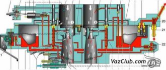
Wiring diagram of a VAZ 21053 carburetor with a description
Setting the ignition timing is the only operation that is performed in the ignition system.
A strobe light is used to set the angle correctly. The technology for performing the work is not complicated. The algorithm of actions is as follows:
- We connect the strobe to the power source and the tip of the spark plug of the 1st cylinder (according to the instructions for the device);
- Remove the plug from the inspection window on the clutch housing;
- We start the engine (it should be idling);
- We direct the beam of light from the strobe into the viewing window;
- We determine the position of the marks (with the angle correctly set, the mark on the flywheel at the moment the strobe light beam flashes should be located between the central and rear marks on the crankcase);
- If the marks are not positioned correctly, make adjustments. To do this, loosen the bolts securing the spark moment sensor and rotating it around its axis until the marks match;
After adjustment, tighten the sensor fasteners, turn off the engine, disconnect the strobe light and replace the plug.
Windshield wiper and washer diagram
- Windshield washer motor;
- Windshield wiper motor;
- Ignition switch;
- Fuse box;
- Windshield wiper and washer switch;
- Conventional numbering of plugs in the switch block;
- Windshield wiper relay;
- Conventional numbering of plugs in the relay blocks and the windshield wiper motor.
Rear window cleaner and washer
- Fuse box;
- Tailgate wiper and washer switch;
- Tailgate glass washer motor;
- Tailgate glass wiper motor;
- Tailgate glass heating element;
- Tailgate glass heating relay;
- Tailgate glass heated switch;
- Ignition switch.
Low/high/fog beam diagram
- Headlights;
- Fuse box;
- Relay for low beam headlights;
- Ignition switch;
- Fog light switch;
- Rear fog light;
- High beam indicator lamp;
- External lighting switch;
- Fog light circuit fuse;
- Headlight switch;
- Headlight high beam relay.
Diagram of hazard warning lights and direction indicators
- Front direction indicators;
- Ignition switch;
- Hazard switch;
- Turn signal switch;
- Side direction indicators;
- Turn signal lamps in the rear lights;
- Turn signal indicator lamp (in the instrument cluster);
- Relay-breaker for direction indicators and hazard warning lights;
- Fuse box.
Symptoms of failure
To check the functionality of the generator, a test lamp is included in its connection diagram. If the device is working properly, the control lights up before the engine starts, indicating that the circuit is in working condition, and after the power unit starts, the light should go out.
It is by the indicator lamp, as well as a number of indirect signs, that a generator malfunction can be identified:
- The signal does not light up when the ignition is turned on, while the other measuring instruments are working. Such a problem may indicate a malfunction of the light bulb itself or an open circuit in its power supply;
- It does not light up and other devices do not work. This may indicate a blown fuse, an open circuit in the instrument panel, or a faulty lock or ignition relay;
- The light glows when the engine is running. This may occur due to breakdown of rectifier diodes, regulator malfunction, short circuit or breakage of stator windings, weak drive tension;
- The lamp works normally, but the Oka generator does not charge (the battery is often discharged). This problem can arise as a result of broken contacts in the wiring suitable for the device, a malfunction of the regulator, a malfunction of the rectifier, broken commutator wires, wear of brushes or slip rings;
- The lamp works fine, but the battery is being recharged (it often boils). Here the reason should be sought in the voltage regulator.
The control lamp allows you to identify mainly electrical faults. As for mechanical breakdowns, they manifest themselves in the form of extraneous noise when the engine is running - hum, squealing, whistling. Often such symptoms are caused by loosening the drive tension. But if adjusting the belt does not eliminate the noise, then you should check the condition of the bearings.
Instrument cluster diagram
- Coolant temperature indicator sensor;
Fuel level indicator with reserve indicator lamp;
- Indicator lamp for brake fluid level and parking brake system;
- Oil pressure warning lamp;
- Coolant temperature gauge;
- Fuse box;
- Ignition switch;
- Parking brake warning lamp switch;
- Parking brake warning lamp relay;
- Brake fluid level sensor;
- Oil pressure warning light sensor;
- Level indicator and fuel reserve sensor.
- Headlight high beam warning lamp;
- Coolant temperature gauge;
- Side light indicator lamp;
- Turn signal indicator lamp;
- Instrument cluster lighting lamp;
- Battery discharge warning lamp;
- Oil pressure warning lamp;
- Fuel level and reserve indicator;
- Fuel reserve indicator lamp;
- Indicator lamp for parking brake system and brake fluid level.
Separation by purpose
By purpose, the equipment is divided into:
- Power supplies;
- Protective means;
- Controls;
- Instrumentation;
- Actuators;
Power supplies
Power sources include the battery and generator. The battery powers the electricity. devices and ensures their operation when the power unit is turned off. After starting the engine, the on-board network is powered from the generator, which also ensures that the battery is recharged.
Protective components
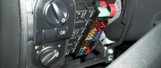
Protective means prevent burnout of electrical appliances and electrical circuits during short circuits. The main protective elements are fuses. For convenience, all protective elements are collected in one place - the fuse box, which in Oka is located under the front panel on the driver’s side.
Controls
Control elements include all components responsible for turning on, switching and turning off electrical appliances. This category combines the ignition switch, all kinds of switches and switches. Most of these elements are located within direct reach of the driver - on the front panel, steering column. But there are switches that the driver acts on through certain components - brake light switches, a sensor for turning on the choke warning light, etc.
instrumentation
Control and measuring devices provide the driver with information about the operation of certain components and mechanisms, operational indicators - fuel level, coolant temperature, oil pressure, etc. Some types of these devices display accurate information, while others are presented in the form of warning lamps that are triggered only when an emergency occurs. malfunctions.
Measuring instruments combine sensors installed on the required components and mechanisms, and signal elements located on the dashboard.
Actuating devices
Actuators are components that perform one or another function - they illuminate, operate components, etc. These include electric motors, lighting lamps, a sound signal, a cigarette lighter, etc.
Diagram of the electric vacuum clutch drive (EPS)
- Gearbox lever handle with EPS forced engagement contact;
- Speed sensor;
- The electronic unit;
- Switch;
- Ignition coil;
- EPS mode switch;
- EPS warning lamp;
- Clutch cable;
- Clutch drive fork;
- Adjusting nuts;
- Vacuum chamber with electromagnet;
- Lock-nut;
- Vacuum chamber cable;
- Seal;
- Clutch lever (pedal);
- Axis;
- Adjusting nut;
- Lock-nut; S1 - Air damper position limit switch; S2 - Accelerator position limit switch.
Connection diagram of relay 602.3747 to the vehicle clutch control system
A1 - Speed sensor 351.3843; A2 — Ignition coil*; AZ - Ignition system switch*; A4 - Relay EPS 602.3747; HL1 - Indication lamp for turning on the air damper type A12-1.2*; HL2 - Electromagnet current indication lamp (EPS control lamp) type A12-1.2*; SV1 - Rechargeable battery*; L1 - Electromagnet type 12.3747; S1 — Air damper position limit switch*; S2 — Accelerator position limit switch**; S3 - Switch on the gearshift lever *; SA1 — EPS mode switch***; PR1 - Fuse 8 A*. Note:
* Standard equipment used on the Oka car. ** The contacts open at the beginning of the accelerator pedal stroke. *** Positions of the key switch SA1: 1 - EPS is off; 2 - EPS enabled; 3 — EPS is on, TDU mode is on.
Malfunctions
The simplified design of the ignition system and the absence of moving components ensures high reliability and ease of maintenance.
There are not so many malfunctions in the Oka ignition system:
- Switch failure;
- Hall sensor malfunction;
- Coil failure;
- Breakage or breakdown of wires, oxidation of contacts;
- Spark plug malfunction;
- Violation of the ignition timing;
Since the ignition system is directly involved in the operation of the engine, any malfunction in it immediately affects the performance of the engine - interruptions occur, the unit does not develop power, popping noises appear, or the unit simply does not start.
Diagnosis of a malfunction is carried out by visual inspection of the wiring and its connections, as well as by sequentially replacing all components with known good ones. A check using measuring instruments allows you to more accurately determine the faulty element.
The search for the problematic element is carried out from the candles. That is, first the presence of a spark is checked on them, then the high-voltage wires are inspected, and then the performance of the coil, switch, and Hall sensor is diagnosed.
The components of the ignition system are non-repairable, so if they break down they must be replaced.
Wiring diagram SeAZ 11116
1/1 — High beam headlights; 1/2 — Low beam headlights; 1/4 — Side light lamp; 2 — Front direction indicator lamp; 3 — Side direction indicator lamp; 5 — Generator with built-in voltage regulator; 9 — Hall sensor; 10 - Ignition coil; 12 - Starter; 13 - Spark plugs; 14 — Sound signaling device; 17 - Water temperature indicator sensor; 18 - Oil pressure warning lamp sensor; 23 - Battery; 25 - Reversing lamp switch; 26 - Brake light switch; 30 — Relay-breaker of direction indicators; 31 — Relay-breaker for the handbrake warning lamp; 32 - Windshield wiper relay; 33 - Additional resistance of the heater electric motor; 35 - Windshield wiper motor; 37 - Electric heater motor; 38 — Radiator cooling fan electric motor; 39 - Electric fan relay; 42/1 — Turn indicator switch; 42/2 — Headlight switch; 42/3 — Windshield wiper and washer switch; 42/4 - Switch for sound warning device; 44 - Ignition switch; 46 — External lighting switch; 48 - Hazard switch; 49 - Heater motor switch; 52 - Instrument cluster; 63 - Speed sensor; 74/1 — Thermal cigarette lighter element; 74/2 — Cigarette lighter lamp; 75 — Brake fluid level sensor; 76 - Handbrake warning lamp switch; 77 — Diagnostic block; 81 — Cartridge for connecting a portable lamp; 83 - Windshield washer pump; 87 — Interior lighting switch in the front door; 89 — Interior lamp; 93 — Sensor for level indicator and fuel reserve; 98/1 — Side light lamp; 98/2 — Turn signal lamp; 98/3 — Brake light lamp; 98/4 - Reversing lamp; 99 — License plate lamp; 104 - Electric fan thermal switch; 108 — Rear fog lamp; 112 - Rear window wiper motor; 113 — Rear window washer motor; 115 — Rear window heating element; 121 — Relay for turning on the heated rear window; 125 - Additional relay; 126 - Relay for high beam headlights; 127 - Relay for low beam headlights; 129 - Starter relay; 133 — Rear window heating switch; 136 — Rear fog lamp switch; 137 - Rear window wiper switch; 138 — Rear window washer switch; 158 - Fuel injectors; 159 — Clock; 168 — Relay for rear fog lights; 169 - Additional brake signal; 170 - Fuel pump relay; 171 - Electric fuel pump; 172 - Idle speed regulator; 173 - Throttle position sensor; 174 - Knock sensor; 175 - Canister purge valve; 176 - Oxygen sensor; 177 - Absolute pressure sensor; 178 - Main relay; 221 - Controller.
Open large picture in a new tab → Oka cars use a single-wire circuit for connecting electrical equipment, i.e., only one wire connects to all electricity consumers. The second “wire” connecting consumers to sources of electricity is the car body, or “ground”. This scheme allows you to significantly reduce the number of wires and simplify their installation. The negative terminals of the electricity sources are connected to ground. With this connection, the corrosion of metal body parts due to electrochemical corrosion is reduced.
The sources of electricity in a car are a generator and a battery connected in parallel. The rated operating voltage of electricity sources and consumers is 12 V. However, the voltage in the electrical equipment system, depending on specific conditions, can range from 11 to 14.5 V, and within these limits, consumers remain operational.
All electrical equipment of cars can be divided into the following main systems:
The operation and activation of all systems is controlled by corresponding switches and relays. The supply voltage is supplied to most consumers through the ignition switch 31. The switched circuits for different key positions are shown in the table (see also Chapter 32).
The power circuits of those electrical equipment components whose operation may be required under any circumstances are always connected to the battery and generator (regardless of the position of the key in the ignition switch). These components include the sound signal 4, the cigarette lighter 45, the threads of the brake signal lamps in the rear lights 68, the license plate lights 70, the interior light 58 and the plug socket 11 for a portable lamp. Also directly connected to the power supply are the hazard warning circuits, side light circuits and the high beam headlight signaling circuit.
When operating vehicles, short circuits may occur due to damage to the insulation of wires or electrical equipment components. They cause a sharp increase in current in a short-circuited circuit and, if protective measures are not taken, can lead to rapid discharge of the battery, overheating of the wires, melting of their insulation and fire of the car upholstery.
To protect against short circuits, the vehicle has 11 fuses. Ten of them are located in a plastic block 22, and one fuse 32, protecting the target of the rear fog light, is located in a separate housing in the wiring harness near the rear fog light switch 41. This fuse is rated for a maximum current of 8 A.
The fuse box is located under the instrument panel on the left side of the steering column. Fuses are a thin plate of low-melting metal mounted on a plastic base. Seven fuses (black) are rated for a maximum current of 8 A, and three (green) are rated for 16 A. 16 A fuses are located in the power circuits of electrical components that consume high current (such as the rear window heating element, cigarette lighter, electric motor engine cooling fan, etc.).
The following are the circuits protected by the fuses located in the fuse box.
If a fuse blows, it is recommended to check the circuits it protects, repair the fault that caused the blown, and then install a new fuse. It is not allowed to use any homemade fuses or fuses that are not provided for by the design of the vehicle.
The largest number of fuses is installed in the lighting system, since it has the most extensive and extensive network of wires and is therefore most susceptible to damage and short circuits to ground. The electric motors of the windshield and rear window wipers are additionally protected from overloads by thermobimetallic fuses located in the electric motors themselves. The cigarette lighter is additionally protected from prolonged use by a low-melting alloy washer located in the rear part of the cigarette lighter.
Some electrical power supply circuits do not have fuses at all. As a rule, these are the most critical systems, the trouble-free operation of which is required in emergency situations. For example, the engine ignition system is not protected by fuses, so as not to introduce into it elements that reduce the reliability of the system in operation. If the ignition system fails, the engine will stop running. There are also no fuses in the starting circuit, so as not to reduce the reliability of engine starting. In addition, the battery charging circuit, as well as the relay for turning on the high and low beam headlights, are not protected by fuses.
To connect sources and consumers of electricity into a common circuit on cars, flexible low-voltage wires of the PVA type are used (high-voltage wires are described further on sheet 32). They have durable elastic insulation made of polyvinyl chloride plastic. This insulation is resistant to oil, gasoline and is operational in the temperature range from -40 to 105 ° C. The conductor core of the wires is made of a large number of soft copper wires to ensure flexibility (from 19 for a wire with a cross-section of 1 mm 2 to 84 for a wire with a cross-section of 16 mm 2).
To distinguish the wires in the bundles and easily trace their connections, the wire insulation is multi-colored. It can be painted in a wide range of colors: white, blue, yellow, red, etc. In addition, spiral or longitudinal stripes of white, red, blue or black can be applied to the insulation surface. Thus, no two wires of the same color are found in wiring harnesses. Black wires are used to connect to ground, and mostly pink or orange wires to connect to the “plus” of power supplies. The current flowing through the wires heats them. In addition, this causes a voltage drop in the wires. To ensure that heating and voltage drop do not exceed permissible limits, it is necessary to select the appropriate cross-section of the current-carrying conductors of the wires. The greater the electric current flows, the larger the cross-section of the wire core should be. Therefore, on cars, wires with different core cross-sections are used: 16; 4; 2.5; 1.5; 1.0; 0.75 and 0.5 mm 2.
The greatest current flows when starting the engine through the wires connecting the battery to the starter and ground, as well as the engine to ground. These wires have a cross-section of 16 mm 2. A fairly significant current also flows through the wire connecting the generator to the starter when the battery is charging, as well as when the engine is not running, when all consumers are powered by the battery. Therefore, this wire was chosen with a cross section of 4 mm 2. The same wire connects plug “87” of starter activation relay 25 with plug “50” of starter traction relay 6.
Wires with a cross-section of 2.5 mm 2 are used to supply voltage from the fuse box to the headlight lamps, to connect plugs “30” and “87” of relays 24, 25, 27 and 28 with consumers or the fuse box and to connect electric motor 3 engine cooling fan with relay 24 and ground. The same wires go to contacts “30”, “30/1”, “15” and “15/1” of the ignition switch 31 and to contacts “D”, “I” and “I” of the external lighting switch 44.
Wires with a cross-section of 1.5 mm 2 are used to connect the rear window heating element 64 with the heating switch relay 26 and to connect the plug “87” of this relay to the fuse box.
All other car wires have a cross-section of the current-carrying core from 0.5 to 1 mm 2, since a relatively small current flows through them.
The wires are connected to electrical equipment units and interconnected using convenient quick-release plug connections. An exception is the connection of wires to the battery, to the “30” terminal of the generator and to the bolt of the starter traction relay. For these critical connections, the wire ends are clamped with nuts to ensure maximum reliability of the connections.
To protect electrical connections from water and dirt, the rear portion of the front turn signals is covered with covers. Protective rubber caps cover the ends of high-voltage wires, coolant temperature and oil pressure sensors, the plus terminal of the battery, and the reverse light switch. The sockets for the side turn signal lamps, rear fog lamps and license plate lamps are also capped.
To facilitate installation, all wires are combined into bundles. The wires in the bundles are wrapped with adhesive tape or enclosed in plastic tubes. The harnesses are connected to each other using plug connectors, the blocks of which are made of polyamide plastic. The holes in the body through which the wires pass are covered with rubber seals, which protect the wires from damage from the edges of the holes and prevent water and dirt from penetrating through the holes.
There are four wiring harnesses in total, front (main) harness, rear, front turn signal harness (2 pieces) and battery wiring harness.
The main wiring harness is the front one. It has three branches. Two of them are located in the engine compartment, and the third is in the cabin under the instrument panel. From the passenger compartment to the engine compartment, the wiring harness passes through a rubber seal and branches out after exiting it. The right branch of the harness is laid on the front panel, and the left branch is laid on the left mudguard and front panel of the front end. The wiring harness is attached to the body panels with steel brackets welded to the body and plastic clamps.
The harness must be fastened in such a way that it is not too tight, but also does not dangle, as this can lead to chafing of the wires during shaking and shorting them to ground.
Inside the car, the front harness runs under the instrument panel and has small branches to the fuse box, switches, instrument cluster, ignition switch and other electrical components. A fuse box is installed on the left side under the instrument panel, and behind it, all auxiliary relays (except the ignition relay) are mounted on a bracket.
The front harness is connected to the rear wiring harness using three plug connectors: two-pin, six-pin and eight-pin. The rear harness runs rearward under the floor mats on the left side of the body floor and has branches to the right side turn signal and dome light switch in the right door pillar, to the parking brake warning light switch, up to the dome light and down in front of the rear seat to the right rear light. From the rear right lamp the harness goes up and near the right hinge of the rear door it goes to the door and goes to the rear window wiper motor and the rear window heating element. The rear harness is attached to the body floor with adhesive tape.
Some electrical equipment components are installed only on some of the vehicles produced.
These components include a cigarette lighter, a rear fog lamp with a switch, and an electrically heated rear window with a corresponding relay and switch.
Colored wiring diagram for the domestic OKA car. The diagram is in high resolution, so to enlarge the picture, click on it. To eliminate errors when working with the circuit, the second version of the OKA electrical equipment circuit is shown below.
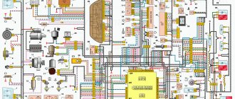
OKA car wiring diagram
1 – side turn signal 2 – front turn signal 3 – headlight 4 – cooling system fan motor 5 – sound signal 6 – fan motor activation sensor 7 – windshield washer motor 8 – spark torque sensor 9 – battery 10 – Oka starter 11 – switch 12 - spark plugs 13 - ignition coil 14 - Oka generator 15 - coolant temperature gauge sensor 16 - low oil pressure warning lamp sensor 17 - socket for portable lamp 18 - windshield wiper relay 19 - brake fluid level sensor 20 - brake signal switch 21 – windshield wiper electric motor 22 – carburetor solenoid valve 23 – reverse light switch 24 – starter relay 25 – relay for low beam headlights 26 – relay for high beam headlights 27 – hazard warning and turn signal breaker relay 28 – cigarette lighter 29 – heater fan switch 30 – additional heater motor resistor 31 – exterior lighting switch 32 – fuse box 33 – fog lamp circuit fuse 34 – rear window heating relay 35 – cooling system fan motor relay 36 – parking brake warning lamp relay 37 – rear window wiper and washer switch 38 – rear window heating switch 39 – rear fog lamp switch 40 – carburetor choke control lamp 41 – hazard warning switch 42 – ignition switch 43 – ignition relay 44 – heater fan motor 45 – level indicator sensor fuel 46 – courtesy light switch in the door pillar 47 – instrument cluster 48 – windshield wiper switch 49 – windshield washer switch 50 – horn switch 51 – headlight switch 52 – turn signal switch 53 – parking brake indicator switch 54 – courtesy lamp interior lighting 55 – switch for the warning lamp for closing the carburetor air damper 56 – rear door glass washer motor 57 – tail light 58 – rear fog lamp 59 – license plate light 60 – rear door glass heating element 61 – rear door glass wiper motor.
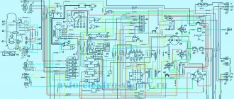
OKA car electrical circuit diagram - another option
1 — headlights; 2 — front direction indicators; 3 — sensor for turning on the electric fan; 4 — sound signal of the Eye; 5 — electric fan of the engine cooling system; 6 — side direction indicators; 7—sparking torque sensor; 8 — spark plugs; 9 — ignition coil; 10 — electric motor of the windshield washer pump; 11 - battery; 12 — Oka car generator; 13 — oil pressure warning lamp sensor; 14 — carburetor solenoid valve; 15 — coolant temperature sensor; 16 — reverse light switch; 17 - switch; 18 — plug socket for a portable lamp; 19 - brake fluid level sensor; 20 - starter; 21 — windshield wiper gearmotor; 22 — relay-interrupter for direction indicators and hazard warning lights; 23 — relay for turning on the high beam headlights; 24 — relay for turning on low beam headlights; 25 — starter activation relay; 26 — relay for turning on the electric fan; 27 — fuse block; 28 — relay-interrupter for the parking brake warning lamp; 29 — windshield wiper relay; 30 — rear window wiper and washer switch; 31 — rear window heating switch; 32 — rear fog lamp switch; 33 — switch for the carburetor air damper warning lamp; 34 — fog light circuit fuse; 35 — control lamp for the carburetor air damper; 36 — alarm switch; 37 — external lighting switch; 38 — relay for turning on the heated rear window; 39 — heater fan motor switch; 40 — brake light switch; 41 — cigarette lighter 42 — additional resistor for the heater fan electric motor; 43 — ignition switch relay; 44 — ignition switch; 45 - three-lever switch; 46 — interior lamp; 47 — lamp switches located in the door pillars; 48 — instrument cluster 49 — parking brake warning lamp switch; 50 — sensor for level indicator and fuel reserve; 51 — electric motor of the heater fan; 52 — rear lights; 53 — rear window wiper gearmotor; 54 — rear window heating element; 55 — license plate lights; 56 — rear fog lamp; 57 — electric motor of the rear window washer pump; A - the order of conditional numbering of the plugs in the spark-torque sensor housing; B - the order of conditional numbering of the plugs in the gear motor blocks of the windshield and rear window wipers and the windshield wiper relay breaker; B - the order of conditional numbering of plugs in the blocks of the ignition switch and three-lever switch; G - the order of conditional numbering of plugs in the blocks of the instrument cluster.
Oka is a general designation for a family of cars also known as VAZ 1111, VAZ-11113 (LADA OKA), SeAZ-1111, KamAZ-1111, Astro 11301.
Produced with various modifications from 1987 to 2008. In this publication you will find a description of fuses and relays in an OKA car with block diagrams and their locations. Note the fuse responsible for the cigarette lighter. In conclusion, we suggest that you familiarize yourself with the OKA electrical circuit.
Design
VAZ-2110 injector 8 valves: electrical diagram with description
The ignition system of the VAZ Oka consists of only seven main elements:
- Auxiliary relay;
- Egnition lock;
- Circuit breakers;
- Switch;
- Spark moment sensor;
- Coil;
- Candles;
All elements are connected to each other by wiring.
Using the ignition switch, the driver controls the power supply to the system from a source - the battery, while the voltage passes through the auxiliary relay and fuses. The lock has three positions - “0”, in which all electrical consumers are turned off, “1” - voltage is supplied to the ignition system and a number of other devices, and “2” - current is supplied to the starter. This switching sequence ensures that the ignition system is activated at the moment the engine starts.
Spark torque sensor
The spark timing sensor is one of the main ignition components, since it sets pulses that are subsequently converted into a spark discharge between the spark plug contacts. This sensor is driven by the camshaft, which allows you to accurately set the timing of the spark in the cylinders.
The main working elements of the unit are the Hall sensor and a special screen with slots mounted on the drive shaft interacting with the camshaft. The interaction of these elements leads to the emergence of control impulses.
The adjustment is carried out by two regulators - vacuum and centrifugal, included in the design of the spark generation moment sensor.
Until 1989, Oka used a sensor of type 55.3706, and after that it was replaced by model 5520.3706.
Switch
The switch acts as a circuit breaker for the primary winding of the coil, using control pulses coming from the spark sensor. Circuit interruption in the switch is performed by the output transistor. The switch is completely electronic, without any moving elements, so the ignition system is contactless.
Several types of switches were installed on the VAZ-1111 and 11113 - 36.3734, 3620.3734, as well as HIM-52. The switch is installed in the engine compartment near the engine panel. It is secured with two bolts, so replacing the switch is quite simple.
Coil
Oka received a two-terminal ignition coil, which made it possible to remove the distributor from the design.
It is noteworthy that the high voltage in this coil is supplied simultaneously to both spark plugs. Moreover, due to the offset strokes in the engine cylinders, only one spark discharge is working, the spark on the second spark plug is the so-called “idle”.
Wires, spark plugs
All wiring consists of low and high voltage wires. The first ones are used to connect all the components up to the coil. These are ordinary wires of small cross-section, which is quite sufficient, since the voltage in the circuit up to the coil is low.
High voltage wires are used to connect the coil terminals to the spark plugs. For ease of connection, lugs are installed at the ends of these wires.
Recommended for use on Oka are spark plugs of type A17DVR - with an extended thread and an interference suppression resistor, as well as their analogues.
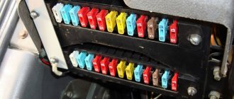
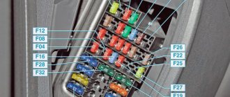
Fuse box
The main fuse box is located in the passenger compartment under the dashboard on the driver's side.
p, blockquote 4,0,1,0,0 —>
The numbering goes from left to right, from 1 to 10 and will be printed on the block cover.
Description
| 1 | 16A Heater fan electric motor, Relay (winding) and sensor for turning on the electric motor of the engine cooling system fan, Relay (winding) for turning on the rear window heating, Electric motors for the rear window wiper and washer, windshield washer |
| 2 | 8A Carburetor solenoid valve, Windshield wiper relay and motor, Turn signals and relay-interrupter for turn signals and hazard warning lights (in turn signal mode), Turn signal warning lamp, Tail lights (reversing lamps), Alternator field winding (at start-up) engine), Carburetor choke warning lamp, Relay breaker and warning lamp for parking brake system and insufficient brake fluid level, Oil pressure warning lamp, Battery discharge warning lamp, Coolant temperature indicator, Fuel level indicator with reserve warning lamp |
| 3 | 8A Left headlight (high beam), High beam indicator lamp |
| 4 | 8A Right headlight (high beam) |
| 5 | 8A Left headlight (low beam) |
| 6 | 8A Right headlight (low beam) |
| 7 | 8A Left headlight (side light), Left rear light (side light), License plate lights, Side light warning lamp |
| 8 | 8A Right headlight (side light), Right rear light (side light), Instrument cluster lamp, Cigarette lighter lamp |
| 9 | 16A Direction indicators and relay-breaker for direction indicators and hazard warning lights in hazard mode, Rear window heating element and relay (contacts) for its activation |
| 10 | 16A Electric motor of the engine cooling system fan and relay (contacts) for turning it on, Sound signal, Plug socket for a portable lamp, Interior lighting, Tail lights (brake lamps). Cigarette lighter |
Fuse number 10 at 16A is responsible for the operation of the cigarette lighter.
Maintenance, repair
Of all the car’s electrical appliances, only power supplies require maintenance:
- Battery (periodic recharging using chargers, monitoring the level and density of the electrolyte);
- Generator (periodic check of drive tension, replacement of worn graphite brushes).
It is also important to monitor the condition of the wire insulation and prevent it from being damaged to avoid a short circuit. Oxidation of contacts often occurs at the wiring junctions, which can lead to failure of electrical appliances
Most of the electrical network components are maintenance-free and must be replaced if they fail. Such elements include light bulbs, small electric motors, switches, relays, fuses, and sensors.
In the starter, generator, electric. In the heater and cooling system fan motors, mechanical breakdowns may occur - wear of bearings, bushings, brushes. All these components are repairable and it is often possible to restore their functionality by disassembling, troubleshooting and installing new parts to replace worn ones.
Relay block
On the left side under the instrument panel there is a block of five identical relays (90.3747-10 / 113.3747-10 / 2105-3747210-20)
p, blockquote 9,1,0,0,0 —>
Scheme
Designation
| 1 | Engine radiator fan relay |
| 2 | Low beam relay |
| 3 | High beam relay |
| 4 | Starter relay |
| 5 | Heated rear window relay |
Dismantling the carburetor OKA 11113
Before proceeding with dismantling the carburetor, you should decide on the necessary tools.
Sequence of operations
The hood of the car is opened and the negative terminal is removed from the battery. The air damper is attached to the rod using a 12mm bolt. This bolt is slightly loosened with an open-end wrench.
The carburetor choke bolt of an OKA car is loosened using an open-end wrench.
Now you need to loosen the bolt that secures the air damper housing to the bracket. This is done with the same open-end wrench.
The bolt on the OKA carburetor bracket is loosened with an open-end wrench
After this, the air bolt is completely unscrewed. The rod is disconnected from the damper.
The choke rod of the carburetor of the OKA car is removed manually
Using a flat-head screwdriver, the end of the intermediate rod is unscrewed from the lever on the throttle valve.
The intermediate rod of the OKA carburetor is removed using a flat screwdriver
Now the ventilation hose is manually removed from the carburetor fitting.
The ventilation hose from the carburetor of an OKA car is removed manually
All wires are manually removed from the forced idle economizer.
The wires of the OKA car idle economizer are disconnected manually
The vacuum regulation hose is manually removed from the carburetor fitting.
Manually removing the vacuum regulator hose on the OKA carburetor
Use a flathead screwdriver to loosen the clamp on the main carburetor fuel hose. This hose is then removed from the fitting by hand.
Using a screwdriver to loosen the clamp of the main fuel hose of the carburetor on an OKA car
Using a 10-mm open-end wrench, unscrew the 2 bolts holding the bracket with the air filter. The bracket is removed.
The OKA car air filter bracket is removed manually
Now the carburetor is held in place only by the two front nuts. They are unscrewed with a 14mm open-end wrench. The carburetor is manually removed from the mounting studs.
After unscrewing the fastening nuts, the carburetor is removed from the OKA car manually
Installing the carburetor is done in the reverse order.
Additional relays
Depending on the configuration and design, additional relay placement is possible.
p, blockquote 13,0,0,1,0 —>
Scheme
Purpose
- Hazard warning and direction indicator relay (494.3747 / 2105-3747010-01) - located behind the instrument cluster.
- Front wiper relay (RS-514 (2101-5205150)) - located under the upholstery, left side panel.
- Parking brake warning lamp relay (RS-492 (2101-3803150)) - located behind the instrument cluster, next to the turn signal relay (see point 1).
- Additional relay (90.3747-10 / 113.3747-10 / 2105-3747210-20).
- Ignition relay (90.3747-10 / 113.3747-10 / 2105-3747210-20) - secured with a self-tapping screw from inside the instrument panel.
Oka oil pressure sensor photo where it is located
I decided to install an oil pressure gauge. For what ? just . In theory, everything is simple - you need an adapter (tee) to install an oil pressure sensor, a pressure sensor and the indicator itself (I used both and the third from a VAZ-2106). I bought everything for about 250 rubles (2002). When installing the adapter in place of the emergency oil pressure sensor (2101-3810600), the oil filter flange broke off!! Although I pulled with a regular open-end wrench without any extensions! The flange is made of aluminum alloy and is quite fragile. The next day I had to go to Moscow and buy this filter flange (1111-1012024) and its gasket 1111-1012030. The next day (I did everything in the evening after work) I began installing the flange. When installing the flange, I broke the “6” key. (the flange is secured with two M8x30 screws with a 6-point hexagon socket) Having decided that I had tightened it enough, I filled it with oil and drove off without looking. After 5 km, all the oil leaked out and we had to go back in tow. The next day I bought oil (Luxoil Extra 0W40 - the cheapest of the liquid ones, since it was heading towards winter), a high-quality set of hex keys, and a sealant gasket. Spitting on the advice of car manufacturers who do not recommend installing oil system parts on sealant, I installed a flange with a paronite gasket on the sealant, applying sealant on both sides of the gasket, only trying to spread the sealant in a thin layer and letting it dry longer so as not to get into the oil system. I started installing the adapter. This also has its pitfalls. Firstly, the engine compartment of the OKI is cramped, and installing an adapter with pressure sensors (for the pointer and for the warning lamp) is inconvenient - the mudguard gets in the way. And secondly, the main thing, it seems to me, is that there is a danger of these sensors-adapters-fittings touching the mudguard when the power unit vibrates - on bumps, etc. It is impossible to position the sensor so that the sensor is pointing upward at OKE - the filter gets in the way. Place it so that the sensor is pointing down? There is a danger of them touching the ground. Consequences? - see above . Therefore, I removed the mudguard (right mudguard 1111-2802022), with difficulty unscrewing the rusty screws, and installed the tee so that the sensor axis is directed approximately horizontally. After this, in my opinion, there was much less dirt in the engine compartment. And only the next day (the sealant polymerizes for a day) I filled it with oil and was on wheels.
From the oil pressure indicator I removed the useless wiring harness from OKE and the backlight and emergency pressure lamps. I installed female type terminals on the wires suitable for the indicator and connected them directly to the oil pressure indicator according to the following photo:
What does the pressure indicator show? In the speed range from idle to 3000. 4000 - approximately 4 atm, the overpressure increases approximately in proportion to the engine speed up to the maximum (8 atm at a speed of 5000. 6000). The readings vary somewhat, obviously depending on the temperature, voltage in the on-board network, type of oil and etc. Over the two years since the installation of the oil pressure indicator, the oil pressure at idle has decreased slightly - from 4.4.5 atm to 3.5. 4 atm. Moreover, when changing the oil for the last time, I filled in a mixture of Luxoil extra oils 0W40 -1.5 liters and 5W50 - 1 liter. — no changes in the pressure indicator readings. November 19, 2004
December 13, 2006 Over the past 2 years, the oil pressure at idle has remained almost the same - 3.5. 4 atm, the maximum at high speeds decreased slightly to 6.7.5 atm. The oil I currently use is Yukos System 0W-40, there is practically no difference compared to the previous Luxoil.
Installation of an oil pressure gauge on the OCU Installation of an oil pressure sensor on the OCU Installation of a device indicating oil pressure on the OCU Installation of an oil pressure indicator from the VAZ-2103 on the OCU Installation of an additional engine oil pressure gauge in the OCU Installation of additional devices on the OCU