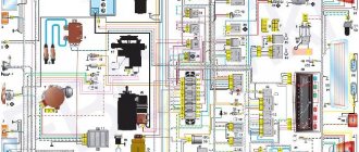
Carburetor engine fuel system
(Fuel injection system)
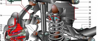
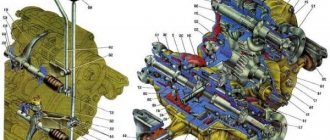
| 1 – fine fuel filter; 2 – fuel pump; 3 – transverse rod of the carburetor control drive; 4 – carburetor; 5 – corrugated hose for intake of heated air from the exhaust manifold area; 6 – cold air intake pipe; 7 – thermostat; 8 – air filter housing; 9 – crankcase gas exhaust pipe; 10 – air damper drive cable; 11 – air damper control handle; 12 – plug; | 13 – hose of the fuel tank and filler neck; 14 – separator and hatch hose; 15 – separator hoses; 16 – separator; 17 – fuel receiver with fuel level sensor; 18 – fuel tank; 19 – throttle valve control pedal; 20 – fuel supply line; 21 – fuel drain line; 22 – check valve; 23 – longitudinal thrust. |
Diagram of a power system with two fuel tanks (Niva with a long wheelbase)
The fuel supply is located in a tank located under the rear seat and covered with a metal casing. The tank is stamped from leaded steel sheet, its upper and lower halves are welded together. The filler neck is connected to the tank by two hoses; The lower (thick) hose is used to fill fuel, the upper (thin) hose is used to remove displaced air during refueling.
The hoses are fixed with clamps. The tank plug is sealed. On each side in the upper part of the tank, fittings extend from it, onto which thin plastic tubes for ventilation of the tank are placed. They are connected to a separator, which, in turn, communicates with the atmosphere through a tube exiting near the filler neck. On vehicles with a toxicity reduction system, the separator is connected by hoses and pipelines to the adsorber in the engine compartment. The design and operation of this system are described in the section Fuel system (injection).
A fuel receiver with a fuel level sensor is attached to the top of the fuel tank on six studs through a rubber gasket. Fuel is drawn from the tank under the influence of vacuum created by the fuel pump. To pre-clean the fuel, use a mesh filter at the end of the fuel receiving tube of the tank.
From the tank, fuel flows through a rubber hose into a pipeline leading into the engine compartment, and then through a rubber hose to the fine filter. Filter – with a paper filter element, non-separable design. There is an arrow on its body, which must coincide with the direction of fuel movement (forward).
After the filter, the fuel enters the fuel pump and then into the carburetor (these units are also connected to each other by rubber hoses). Excess fuel from the carburetor (the pump is designed to supply excess fuel) is drained through hoses, a fuel line and the drain pipe of the fuel receiver with a fuel level sensor back into the tank. Fuel circulation prevents the formation of vapor locks in the power system. A check valve is installed in the section of the drain hose in the engine compartment, allowing fuel to flow in only one direction. All hoses of the power system are fixed to the fittings and tubes with clamps.
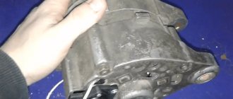
The fuel pump is a diaphragm type, mechanically driven from the eccentric pusher of the oil pump drive shaft and the ignition distributor, with a manual pumping lever. The pump consists of a lower housing with drive levers, an upper housing with valves and fittings, a diaphragm assembly and a cover. The diaphragm assembly is installed between the upper and lower housings.
Two diaphragms are installed on top (working ones), and one (safety) on the bottom: it prevents gasoline from entering the engine crankcase if the working diaphragms rupture. In this case, leaked gasoline is discharged through holes in the external spacer located between the safety and working diaphragms.
The diaphragms, together with the internal spacer and plates (from the outside), are assembled on the rod and secured with a nut. The rod is inserted into the balancer window with a T-shaped shank. A spring is installed between the diaphragm assembly and the lower housing. The upper housing is closed with a lid secured with a bolt. Underneath there is a mesh fuel filter.
The pump is attached to the engine on two studs through a heat-insulating spacer, sealed on both sides with cardboard gaskets. Gaskets are available in thicknesses of 0.30±0.03, 0.75±0.05 and 1.20±0.10 mm. When installing the pump, install a 0.30 mm gasket between the heat-insulating spacer and the engine, and install a 0.75 mm gasket on the outer side of the spacer (facing the fuel pump) and check the minimum protrusion of the pusher from the spacer, which should be 0.8–1.3 mm . To do this, slowly turn the engine crankshaft, pressing the pusher with your finger and periodically checking its protrusion above the plane of the gasket. If the minimum protrusion is less than specified, the outer gasket is replaced with a thinner one, if more, with a thicker one.
The air filter is dry, with a replaceable paper filter element. The filter housing is connected to the carburetor flange through a rubber gasket. It fits over the four studs of the carburetor and is pressed with self-locking nuts through a steel plate. To limit the tightening of the nuts, steel spacers are placed on the studs.
Cold air can enter the air filter housing (through a plastic intake mounted on the filter housing), hot air (through a corrugated hose connected to a steel pipe on the exhaust manifold) or mixed. Switching flows - manually, by turning the thermostat damper flag attached to the air filter housing. When the average ambient temperature is above 15°C, cold air should be supplied, below 0°C - hot air, in the range of 0–15°C - mixed air (damper in the middle position).
Video
Carburetor repair for dips and jerks
Carburetor repair may be necessary if the engine idles unstable, and adjusting the quantity and quality screws does not always help. Often the reason lies in over-enrichment of the mixture, which may be a consequence of incorrect adjustment of the float system or malfunctions in the vacuum economizer system for power modes. In the latter case, a torn diaphragm may need to be replaced or the economizer valve through which fuel is leaking may need to be repaired.
Model 2121 may cause jerking, swaying or dips when moving. In this case, there may be several reasons for their occurrence, which may require carburetor repair to eliminate them. Dips that appear when the throttle valve is slowly opened are often associated with clogging of the idle jet. Here it is necessary to adjust the fuel level and check the level of clogging in the main fuel jets.
If the car gives a deep failure when trying to open the first or second throttle chambers, then in addition to clogged nozzles, the reason may be poor installation of small diffusers in the corresponding sockets.
When the Niva 21213 gives slight twitches at low and medium speeds and accelerates sluggishly, it may be due to poor fuel dosage on the shut-off valve side due to its wear. In this case, repairs are needed in terms of replacing the shut-off valve with a shut-off needle made of metal with a valve that has this needle made of a different material.
Cars of the 2121 series sometimes give failures when any sudden opening of the throttle valves, which then disappear within 5 seconds when the engine is running at the same pace. Often such problems are associated with a malfunction of the accelerator pump, which leads to a lack of or an incorrect drop in gasoline flows. A similar situation can result from a diaphragm rupture, a rubber O-ring on the sprayer holder being destroyed, or the lower part of the valve being destroyed.
1. Wash the filter in gasoline and blow with compressed air. 2. Check the condition of the filter. 3. If the filter or fuel supply pipe is damaged, replace it with a new one. Float mechanism 4. Wash the parts in gasoline and check their condition. 5. Floats must not be damaged. The sealing surface of the needle valve and its seat must not be damaged to impair the seal of the valve. 6. The valve should move freely in its seat and the ball should not hang up. The weight of the floats should not be more than 6.23 g. 7. Replace faulty parts with new ones.
Carburetor adjustment Niva 2121, Niva 2131
2121, 2131
repair
engine
carburetor
Adjusting the carburetor and its drive
Carburetor repair, stages of assembly and disassembly of Niva 2121 carburetor parts, instructions for repairing and replacing the Niva 2131, VAZ 2121 valve. Adjusting the carburetor and its drive Design of the Niva 2121, Niva 2131 carburetor, do-it-yourself repair, carburetor engine repair, inspection and testing
Performed when replacing the Niva 2121 carburetor, as well as when drive parts are worn out or replaced.
When the gas pedal is fully pressed, the throttle valves of the VAZ 2121 should be completely open, and when released, they should be closed. If this is not the case, disconnect the end of the drive's longitudinal rod from the bracket on the valve cover (see Removing the Niva 2131 carburetor from the engine).
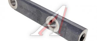
Using an “8” wrench, loosen the lock nut of the tip (for clarity, we show the operation with the rod removed).
By unscrewing or twisting the tip, we achieve the correct adjustment. Tighten the locknut. We also check the distance between the centers of the transverse rod ends, which should be 80 mm. If the adjustment range is not enough (the dampers do not open completely), bend the gas pedal up.
Carburetor VAZ 2121, Niva 2131
Design and operation of the carburetor
Carburetor design Niva 2121, Niva 2131
Adjusting the carburetor and its drive
Carburetor adjustment Niva 2121, Niva 2131
Fuel level in the float chamber
Adjusting the fuel level in the float chamber of the carburetor Niva 2121, Niva 2131
Adjusting the starter
Adjusting the carburetor starting device Niva 2121, Niva 2131
Checking the locking mechanism of the second camera
Checking the operation of the locking mechanism of the second camera Niva 2121, Niva 2131
Adjusting the idle system
Adjusting the idle system Niva 2121, Niva 2131
Disassembling the carburetor
Disassembling the carburetor Niva 2121, Niva 2131
Checking and replacing the solenoid valve
Removing and installing the carburetor solenoid valve Niva 2121, Niva 2131
Carburetor fuel filter
Removing and installing the carburetor fuel filter Niva 2121, Niva 2131
Checking the economizer switch
Checking the forced idle economizer switch Niva 2121, Niva 2131
Disassembling and assembling the carburetor
Assembling and disassembling a carburetor on a Niva 2121, Niva 2131
Disassembling and assembling the carburetor coverAssembling and disassembling the carburetor cover Niva 2121, Niva 2131 |
Removing and installing the carburetor from the engineInstalling and removing a carburetor from a Niva 2121, Niva 2131 car Engine systems VAZ 2121, VAZ 2131Operation and maintenance of the fuel injection, ignition, exhaust system Niva 2121. Injection engine, carburetor engine. Design of the carburetor and injection power system of Niva 2131. disassembling and assembling the engine with your own handscarburetor, adjustment and checkinjector, troubleshooting and inspectioncooling system, design and maintenancecarburetor power system, deviceinjection power system, repair, photocarburetor, inspection and testingignition system, device and repairengine injection systemexhaust system, maintenance |