I want to relieve the power part of the switch by installing an additional one from the basin 2108. I bought 0529.3734 with a connector. I found information on the Internet about AZLK, cadet C16NZ, digested it, summarized it and drew it beautifully and clearly. All that remains is to test)
Brief description: The high cost of native switches and the impossibility of finding them in the village / on the road makes you think about installing a switch from the basin. They cost 300 rubles and can be found in any general store. And if you make connectors, you can return to your native one in 5 seconds. So what do we do. We leave the adjustment of the OZ to the native switch. And we’ll entrust spark control to a new one. We remove the signal for adjusting the OZ from D and hang it on the 6th leg.
Theory of our ignition system:
A magnetoelectric sensor is built into the ignition distributor, which generates control pulses and supplies them to the input of the electronic ignition unit. The sensor consists of a rotor with permanent magnets and an inductive coil. When the magnetic pole of the rotor passes past the inductive coil, an alternating voltage is induced in the latter. The electrical signal from the coil is fed to the input of the semiconductor unit, which generates current in the primary circuit of the ignition coil (high-voltage transformer). During certain phases of voltage change in the inductive coil circuit, a sharp decrease in the current in the primary circuit of the ignition coil occurs. In this case, a high voltage is generated in the secondary winding of the ignition coil, which is supplied by the ignition distributor to the spark plugs in the order of operation of the engine cylinders. A capacitor is located in the distributor to reduce interference to radio reception. The ignition timing is adjusted by the engine ECU based on signals from various sensors that control the engine operating mode.
Adjusting the initial ignition timing
The non-contact ignition system is designed for forced ignition of the working mixture compressed in the engine cylinder. Ignition of the mixture is achieved using a spark between the electrodes of the spark plug. High power performance and good fuel efficiency of the engine while reducing the amount of harmful emissions into the atmosphere with exhaust gases are ensured by an electronic ignition timing control system (IAC), which is controlled by the engine ECU. In order to calculate the ignition timing, the ECU must monitor various parameters: – crankshaft speed; – engine load (vacuum in the intake manifold); - Atmosphere pressure; – engine coolant temperature; – formation of a high voltage reference signal. This signal allows the ECU to calculate the rotation speed and angular position of the crankshaft; – formation of a low voltage reference signal. The corresponding wire is connected to ground in the ignition unit. The presence of voltage may interfere with the normal operation of the ignition system. Therefore, a break in this wire can lead to a deterioration in the performance of the SRZ and a decrease in engine power; – shunt control. When the crankshaft rotation speed reaches about 400 rpm, the ECU supplies a 5 V control voltage to terminal SZ to switch the ignition timing control function from the ignition unit to the ECU. If there is a short to ground or a wire break, the ECU sets fault code 42 and transfers the function of regulating the ignition timing to the ignition unit. In this case, the engine operates with the initially set ignition timing plus a small advance angle included in the operating algorithm of the ignition unit. – generation of an ignition timing control signal. Through terminal D10 and the corresponding wire, the ECU transmits control pulses to the ignition unit. The ECU does not determine the absolute value of the ignition timing. It calculates only the correction relative to the initially set (base) ignition timing value and supplies control signals that are slightly retarded or ahead of the reference signal received from the ignition unit. For this reason, incorrect initial setting of ignition timing leads to a general shift in ignition timing in all engine operating modes. A break or short to ground in the signal wire of the SRZ leads to the issuance of fault code 42 and the shutdown of the SRZ. In this case, the advance angle is set by the ignition unit without the participation of the ECU. When adjusting the ignition timing, the ECU processes the signals from the intake manifold pressure (MAP) and coolant temperature (TCT) sensors. The ECU operation algorithm provides for: -• increasing ignition timing at low DBP signal voltage and at low coolant temperature; • - reduction of ignition timing at high voltage of the DBP signal and at high coolant temperature. Therefore, detonation, as a rule, occurs when the voltage of the DBP signal is low or when the electrical resistance of the DTG thermistor is high. A decrease in engine power can be observed when the DBP signal voltage is high or when the electrical resistance of the DTZ thermistor is low.
A command is received via the “shunt” wire to turn off the SPD adjustment (after closing contacts A and B). After this, the initial OZ is set. Shunting is usually short-circuiting with less resistance.
The switch is an electronic component to ensure the operation of a contactless ignition system. It is transitional between contact and microprocessor. The latter, the most advanced, allows you to control the torque using data read from sensors - oxygen, speed, engine speed and others. But there are still many cars on the roads that have both contact breakers and contactless ones. Therefore, for maintenance and diagnostics, you need to know the purpose of all elements, as well as troubleshooting methods and their main symptoms. Before testing the switch, review all parts carefully.
Signs of a faulty switch: how to check the switch yourself.
Purpose and design features of the switch.
A switch is one of the elements of a car's electrical equipment. His task
– ensuring normal operation of the contactless ignition system. The assembly is fastened in the engine compartment.
The device is different
reliability, ability to withstand severe vibrations and shock loads. This is very important, because the switch housing contains sensitive electronics.
At the heart of the VAZ switch
– standard L 497 microcircuit, which controls an “NPN” type transistor.
>Scheme feature
– possibility of programming by the user and setting the required delay coefficient. Starting a cold engine directly depends on the correctness of this indicator.
Thanks to precise settings
, you can speed up the crankshaft rotation speed (while eliminating failures in operation) and guarantee high-quality traction of the power unit.
The main parameters of the switch device include:
Voltage range – from 6 to 16 Volts; operating voltage level – 13.5 Volts; ensuring an uninterrupted spark when the crankshaft rotates in the range from 20 to 7000 rpm; switching current – from 7.5 to 8.5 A.
Signs of a faulty switch.
One of the main symptoms of a faulty switch is loss of spark.
. The engine starts hard and stalls from time to time, causing interruptions in operation.
But don't rush to replace it
- it is important to verify the reason, because
loss of spark can occur for a number of reasons
- failure of the Hall sensor, rupture of the timing belt, malfunction of the ignition coil, poor contact in the distributor cap, problems in the wiring, and so on.
Therefore, first of all, a comprehensive diagnosis is necessary. The fastest and most effective way in this case can be a car diagnostic scanner. For the most part, this type of device is quite easy to use and has an affordable price. Of those presented on our market, we can recommend paying attention to the multi-brand scanner Scan Tool Pro Black Edition.
The advantages of this model include diagnostics of not only the engine, but also other components. Compatible with 99% of new and old cars since 1993, quite easy to use and has wide functionality.
If diagnostics of other nodes does not produce results
, then we can move on to our “hero”. But how to check the switch, since the device has a very complex design?
How to check the switch yourself.
Most car enthusiasts don’t bother with diagnostics and simply install a new unit. This method has its advantages.
Firstly
, there is no need to waste time checking - just install a new part.
Secondly
, you can immediately determine whether this is the reason or not. In fact, there is no need to be afraid of the work, because checking the switch takes a few minutes.
So, to carry out work at home, a test lamp (nominal voltage should be 12 Volts) and a standard set of keys are enough.
With their help, you can verify the presence or absence of pulses, and later make a decision about the serviceability of the device itself.
Algorithm for checking the switch:
To begin work, it is advisable to disconnect the battery so as not to accidentally short-circuit the wiring that you will unscrew.
Using an eight-point wrench, unscrew the nut and remove the wiring from the ignition coil marked “K”. This wire is easy to recognize - it is brownish in color and goes to the terminal labeled one on the switch;
Connect this wire through a control light to terminal “K” on the ignition coil, and then connect the battery;
Turn on the engine starter and observe the lamp's actions. If it blinks, then the switch is working. If the light bulb does not show any signs of life, then the only way out is to replace the device.
If there are doubts about the serviceability of a part, the check should be carried out on a special stand (there is always one at the service station).
In this case, it is possible not only to determine whether the product is working, but also to measure the duration of the pulses.
When the first suspicions appear, you should not immediately change the switch or spend money on a specialist. You are quite capable of doing the job yourself.
Moreover, now you know how to check the switch on the VAZ 2109 and other models of the domestic brand. All that remains is to allocate time and prepare a minimum set of tools. Have a good trip and of course no breakdowns.
Sometimes when diagnosing a carburetor gasoline engine of a passenger car, difficulties arise in determining the cause of a particular malfunction. This happens because the symptoms of their manifestation are very similar. For example, carburetor malfunctions and ignition system malfunctions will have almost the same effect on engine performance. In this article we will try to understand what problems in the operation of a car engine arise due to a malfunction of the ignition system.
Car engine does not start
— Battery is faulty
— The switch is faulty
— Hall sensor is faulty
— The insulation of high-voltage wires is “broken”
— The distributor cover is “broken” or is heavily oxidized, its contacts are destroyed
— Ignition distributor rotor (slider) burnt out
— The ignition coil is faulty or its cover is “broken”
— High-voltage wires are connected in the wrong order
— Defective spark plugs, their insulation is “broken,” the gap between their electrodes does not correspond to the norm
— Incorrect ignition timing
Ignition is either too early or too late. How to correctly set the ignition timing on VAZ 2108, 21081, 21083 engines is described in detail on the page “Setting the ignition timing of VAZ 2108, 2109, 21099 cars.”
— The low voltage circuit of the ignition system is faulty (contacts have oxidized, wires are broken, connectors have come off...)
Read more about the inability to start the carburetor engine of VAZ 2108, 2109, 21099 cars in the article “The carburetor engine does not start (reasons related to the ignition system).”
For comparison, you can see what reasons exist that the engine cannot be started due to a carburetor malfunction.
The car engine runs erratically (troits) or stalls at idle
— The gap between the electrodes of the spark plugs does not correspond to the norm
— Heavy carbon deposits on the spark plug electrodes
— Defective spark plugs (“insulator broken”)
— Incorrect ignition timing
— The switch is faulty
— The centrifugal ignition timing regulator in the distributor is faulty (weights stick, their springs are weakened or broken, damper rings are lost)
Causes of rough idle related to the carburetor are outlined on the “Rough Idling” page.
Dips and jerks in engine operation
— Incorrect ignition timing
— The gaps between the electrodes of the spark plugs do not correspond to the norm
— Defective spark plugs
— The noise suppression resistor in the rotor (runner) of the distributor burned out
— Wear or damage to the contact carbon in the distributor cover
— Current leakage through “broken” insulation of high-voltage wires, spark plug insulator, ignition coil cover
For the causes of malfunction related to the carburetor, see the page “Failure when pressing the gas pedal.”
The engine does not develop full power, its throttle response is reduced
All of the above causes of malfunctions lead to loss of power, throttle response of the car engine, and increased fuel appetite. You can only add
— Malfunction of the vacuum ignition timing regulator in the distributor due to jamming of its plate
Notes and additions
Five more articles on the site on the ignition system of VAZ cars
A power supply and a pair of wires are all that constitutes a car ignition switch. But on the other hand, this is a rather complex and responsible unit. Today it continues to evolve, showing better and better combustion ratios. At the same time, advanced devices are able to work effectively on the AI-93, increasing the engine output at low speeds.
Switch Specifications
The VAZ switch circuit is based on the L497 microcircuit, which controls the output NPN transistor. A special feature of the microcircuit is the ability to program the recovery time of the delay coefficient, which is important for trouble-free starting of a cold car power unit. This feature of this electronic component of the switch allows for rapid acceleration of the crankshaft speed without failures in operation, which ensures constant engine traction.
Analogues that are sometimes used in the design of the VAZ 2108 switch are the KR1055HP1, KR1055HP2, KR1055HP4 microcircuits. However, these electronic components are found quite rarely in the design of the device. Main technical parameters of the device:
The design of the device is designed for use in single-wire power circuits on cars in which the body plays the role of a negative terminal. Installation of a device mounted on the L497 chip is carried out in a specially designated place using standard fasteners.
What is it for, where is it located and what does it look like?
As was said, the switch is needed for driving on low-octane gasoline. This fuel costs much less than premium grades. At the same time, the engine output still remains at a high level due to better ignition of the air-fuel mixture. Thus, the switch is a device that promotes the appearance of a productive spark in the ignition unit. It can be considered a microcomputer stimulating the converter. Naturally, the switch must rely on some data. In our case, these are signals from the synchronization sensor.
On cars with LPG, the switch performs one more task: it tests the ignition components, adjusting the OZ with the autopilot during switching to methane.
Structurally, the element can be combined with the ECU. In this case, it is located on the distributor (VAZ 2106, 2107) or next to the converter - on the ZIL TK102U. The option of being on a separate metal platform is no exception. As a rule, this is either a car fender or a partition under the hood (Ford). And on German Audis the switch is installed in the engine compartment under the windshield. It is provided with a protective casing made of moisture-proof material.
Signs of a broken switch
During the operation of the car, unpleasant symptoms may occur, indicating a malfunction of the ignition system.
A possible reason for this may be incorrect operation of the switch. Here are the most common symptoms that should suggest a possible breakdown of this device:
- Can't start the engine. There is no spark when the starter is running.
- The engine starts and runs normally at low and medium speeds, but cannot be revved up at high speeds. The engine is not running at full power.
- The car stalls when moving away, although it idles stable.
- The engine starts, but does not run for a long time and immediately stalls.
- The engine begins to operate unstably - “triple”, reaching a certain speed level. When cold it can start quite normally.
- The engine may periodically, without any pattern, stall, then work normally again. The battery discharge indicator lights up. The tachometer needle shows sharp changes in the number of revolutions.
Design and principle of operation
The first switches were extremely primitive. A simple circuit of transistors was regulated using an electrical impulse. The device did not last long in this form. The era of high technology has arrived, thanks to which more effective innovative solutions have begun to be applied.
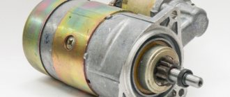
On cars assembled in the Russian Federation, the spark stimulator was first used on the VAZ-2108 car. The device belonged to the 36.3734 series, also of native production. Subsequently, more modernized switches with different design and technical designs began to be used. However, combined or composite assembly technology has always remained unchanged for Russian microcircuits. And its advantage is that it is repairable, unlike the same foreign analogues.
Today, a switch is a combination of several elements: spark plugs, transistors, sensors. It can be used in hybrid or thyristor ignition. Electrical impulses are controlled automatically, which provides a number of practical advantages:
- no interruptions at maximum speeds;
- increasing the reliability of the unit;
- possibility of increasing the engine cylinder capacity.
And when the Hall element was introduced, and the switch began to control several converters at once, the advantages only increased. So much so that they began to use a “coil + commutator” tandem on each individual spark plug. Here's what exactly we managed to achieve:
- the spark in the ignition system has become stronger and more reliable;
- power losses in the distributor have disappeared;
- improved idle speed;
- fuel consumption has decreased;
- Starting on a cold engine has stabilized.
The principle of operation of the switch can be imagined as follows. First, the system monitors the position of the engine crankshaft. Then, an inductive Hall sensor included in the distributor design takes readings from the position of the pistons in the cylinders. It also supplies the switch with an impulse. The signal is amplified to 12 volts and sent to a coil. Due to this, the current decreases and the voltage increases.
Nowadays, electronic switches are used for efficient ignition of fuel in VAZ 2109, 2110, 2114 Samara, as well as ZAZ-1102. The 3734 series of these devices is produced under article numbers 3620-, 36- and 78. The tasks of the key here are performed by a productive mosfit, and the current value is controlled by an integrated electrical circuit.
Microprocessor switch with automatic octane corrector “Astro” 962.3734
PURPOSE Microprocessor switch 962.3734 with automatic octane corrector (hereinafter referred to as MKAOC) provides sparking in contactless ignition systems of four-cylinder, four-stroke gasoline internal combustion engines. Installed on cars: VAZ-2105, -2106, -2107, -2108, -2109, -2110, -21213, -2130 and their modifications.
MKAOC allows you to: — automatically adjust the ignition timing depending on the quality of gasoline used, load and other factors, without driver intervention; — monitor the health of the Hall sensor and the switch control circuit; — set the initial ignition timing. Installed on carburetor cars equipped with an analog contactless ignition system.
DEVICE AND PRINCIPLE OF OPERATION MKAOC is built on a microcontroller using a broadband knock sensor. Processing signals coming from standard sensors and a knock sensor allows the system to automatically adjust the ignition timing depending on the quality of gasoline used, load and other factors, without driver intervention. Operates without a knock sensor like a regular switch.
ADVANTAGES OVER OTHER SWITCHES • Automatic adjustment of the ignition timing (IAF) • Diagnostics of faults • Allows you to set the initial ignition timing without special equipment • Reduced fuel consumption (with a working engine with an adjusted carburetor) • Increased engine life • Increased engine traction torque at low speeds • Improved acceleration dynamics • Easier engine starting (multi-spark mode) • Reduced engine noise (sharp reduction in detonation) • Quick shutdown of the ignition coil (0.5 sec.)
TECHNICAL CHARACTERISTICS • Supply voltage 8...16 V • Permissible crankshaft rotation speed 6000 rpm • SPD adjustment range 0...11° • SPD adjustment downwards when starting the engine 3° • SPD adjustment discreteness, per ignition stroke: - to the side decrease (during detonation) 1...2° - towards increase 0.1...0.2° • Switching current 7.5...8.5 A • Maximum current consumption 3 A • Ignition coil shutdown time 0.5 s. • Operating temperature range –40…+85 °C • Weight, no more than 200 g.
I installed it on a free technological hole with a ∅8 mm thread (thread pitch 1.25 mm) on the side of the oil dipstick near the 1st cylinder. Since my engine is well tuned, I didn't notice much of a difference, but I think it gets the job done.
I purchased this device for a long time, it is unknown for what purpose, now I have found where to put it.
kit contents
DD mounting location
switch
Connection diagram
It turns out that the role of commutation is simply to amplify the pulse to the required value. This is true, because it is not without reason that designers compare the described element with Darlington field-effect transistors. Only in the switch the main function is performed by an inductive sensor with three terminals. When a metal plate enters the sensor area, current generation begins. Next, the voltage is applied to the input of the switch. Here the pulse only increases and goes further to the converter.
The ignition switch circuit is quite simple. It's difficult to install. It must be carried out as competently as possible, otherwise there will be no point. An important nuance also concerns the selection of transistors. They must be checked through special measuring equipment, since even seemingly identical semiconductors have very different characteristics.
Below, as an example, is a diagram of a 4-port switch 76.3734 type KET, used on VAZ cars:
- intended for BSZ;
- consists of controller L497 or its analog KR1055ХП2;
- connection to a tachometer located on the dashboard is possible;
- classic connection - through a two-stage amplifier unit.
Now according to his conclusions:
- 1 (output), an amplified pulse is removed from it - connected to the main terminal of the coil;
- 2 (contact) - connects to the negative terminal of the battery;
- 3 (ground) - integrated internally by a block with contact 2;
- 4 - receives power from the battery;
- 5 - outputs constant power, always 12 V.
It is noteworthy that a voltage stabilizer is used between 4 and 5, since there is always resistance here.
A more detailed diagram of connecting the switch to the VAZ 2108 is shown in the photo.
Ignition faults
Testing the coil is a little more difficult. You will need to borrow the same spare part, but 100% working. If after replacing the coil the problem disappears, then it was the coil that was faulty.
You can check the presence or absence of a pulse using a test lamp. It often happens that malfunctions in the ignition system occur during a trip. And the car owner will not always have at hand a spare switch for the VAZ 2108, an ignition coil, a set of spark plugs, and so on. In this situation, you can ask for help from passersby or turn to the services of a tow truck. The driver will probably not be happy with the cost of the latter service.
To get out of this situation and move on under your own power, you must first find out the cause of the malfunction. Testing the switch is done in different ways. But for many methods you need to use special devices and equipment.
Existing types of switches
There are two main types of devices: AC CDI and DC CDI. The first switches were small and simple, using a high-voltage generator in their circuitry. The latter are more common, equipped with four contact groups with minus and plus, as well as separate outputs for the coil and Hall sensor. But the latter function only in the presence of high voltage supplied from an external source.
Switches are also usually classified according to their functional features:
- traditional or stock devices that strictly correspond to the parameters of the car - as a rule, they are installed from the factory;
- sports - they have the ability to increase the upper limit of the number of revolutions of the internal combustion engine, however, this type is the lot of experienced specialists and has the risk of accidents;
- with the ability to adjust the phases of the UZ - an excellent option when you need to equalize the torque of the power plant, improve acceleration characteristics and stabilize engine operation at different speeds.
Of course, switches are usually divided into main types.
Electronic
This type of switch is also called a microprocessor switch with transit keys. It is used to control the converter voltage and reduces the load on the connections, thereby increasing the current capacity.
Advantages of the electronic system:
- possibility of better filling of internal combustion engine cylinders;
- efficient engine output at all speeds.
Hybrid
These systems additionally use a mechanical part - a cam distributor. The electronics are represented by the switch itself and the coil. The unit is very reliable, economical and convenient. For example, if a switch fails, you can switch to an old converter with a slider.
Contactless
A group with transistors, widely used since the early eighties. It replaced the antediluvian classical contact systems. At one time it was considered the most effective, since its performance indicators were much higher than those of other switches.
Dual channel
The same contactless system, but significantly modernized. For example, a conventional BSZ has the same disadvantages of a KSZ - loss of spark energy, instability of idle speed, limitation on adjustment of the SPD, high sensitivity to pollution and humidity. A two-channel system or DBSZ eliminates these disadvantages from the ignition system, providing even higher spark energy through the use of additional coils. Also, problematic moving elements - a slider and a coal - are not used here, and the lid serves only as a protective element. Therefore, it is not subject to burnout.
Interestingly, two-channel ignition was used before. This was implemented on export VAZ-21083. However, switches of this type, also called dual-circuit switches, were not widely used due to the poor quality of the electronics of that time.
One more nuance regarding switches. They may have different outputs. Those with the default number “1” are extremely dangerous for the ignition coils at the moment they experience malfunctions. But the advantage of such devices is that standard converters for contact ignition can be integrated with them.
For the second types of switches, in which output “0” is used by default, conventional coils are completely unsuitable. They will get very hot, or the spark will not flow properly. Such a switch includes, for example, the model for BTsZ 131.3734.
Switch Purpose
The switch is designed to interrupt the electric current flowing through the primary winding of the ignition coil, according to a signal from the Hall sensor. The interruption results in a high voltage current flowing to the spark plugs.
In addition, the switch automatically regulates the period of current accumulation in the ignition coil depending on the crankshaft speed. It also turns off the current supply through the ignition coil when the engine is not running but the ignition is on.
Symptoms of a Switch Problem
Loss of spark by the ignition system is one of the main symptoms of a lack of serviceability of the switch. Naturally, this is accompanied by difficulty starting the engine and interruptions in its operation. However, experts warn that there is no need to rush to replace the element, because similar symptoms are also present in other problems. For example, this also happens when the timing belt breaks, the distributor or ignition coil is damaged, the wiring connections are weak, etc.
In a word, you need to check the switch correctly. But how can you do this without qualifications, because the device has a complex design. There are several practical ways. The first is not to bother and install a new switch. If the problem goes away, then everything is fine. The second method involves using a 12-volt test lamp and a standard set of keys.
Following are the instructions:
- de-energize the battery;
- remove the control wire “K” from the ignition coil - it is often painted brown or red and routed to the main terminal of the switch;
- In its place, install one end of the control lamp, connect the other to wire “K”;
- connect external power supply 12 volts - battery;
- start the engine.
If the lamp starts blinking, the switch is working. The opposite situation, when the indicator does not show any operating signs, will indicate problems with the device. It is unlikely that it has completely deteriorated, then the engine would not start the first time.
Signs of a switch malfunction can be more accurately seen on professional equipment - a special stand. This makes it possible not only to determine whether the device is working, but also to calculate the duration of the pulses. In addition, specialists separately measure the voltage at the output of the Hall sensor - the norm is no more than 0.4 V. The first and second terminals of the switch are also closed when the ignition is on to test for the presence of a spark.
Switch replacement
The functionality of the switch is checked using a test lamp. If the lamp does not blink when the crankshaft rotates, this means that the switch does not send impulses to the ignition coil and needs to be replaced.
In some cases, the problem lies not in the switch itself, but in the wiring. The system may malfunction if the wires that connect the switch to the coil or ignition switch are broken. In this case, a specialist checks the condition and reliability of the wire connection. Detected problem areas can be replaced with new ones, and loose connections can simply be fixed.
The practice of operating switches shows that the cause of problems may be a break in the wires between the ignition distributor sensor and the switch itself. In this case, damaged wires are also replaced.
If the switch cannot be restored, it is replaced. As a rule, this procedure takes no more than 15-20 minutes. At the same time as this service, we recommend that you carry out a full diagnostic of the car's electrical wiring, since engine problems are often associated not only with faulty devices, but also with the condition of the wiring.
Repair and replacement instructions
It is worth noting that modern Russian switches are suitable for output key transistors not only of standard production, and in particular KT890A, KT898A1, but also the foreign analogue BU931. It can be implemented either without a housing or in the TO-220 or TO-3 design.
As for the control circuit, the 78.3734 series switches are suitable for:
- 4-channel amplifier type K1401UD2B;
- domestic microcircuit R1055ХП1;
- foreign L497B SGS-TOMSON.
Before replacing the switch or its components, it is recommended to test the integrity of the wiring and connections of the ignition system. Pay special attention to the generator. It is also a good idea to check the voltage from the on-board network to the Hall sensor.
More details on faults and how to repair them are given in the table below.
Repair VAZ 2108 2109 21099
Friday, July 10th, 2015
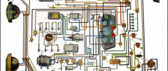
Every owner of the VAZ 2109 should know the ignition circuit Without knowing this circuit, you will not be able to start the car in case of ignition problems. Moreover, this scheme is elementary simple. The VAZ 2109 is equipped with a contactless ignition system. It consists of the following components: switch, ignition coil, distributor, Hall sensor, high-voltage wires and spark plugs. The task of the ignition system is to provide a timely, cyclic spark to the engine cylinders. Let's take a closer look at how the clamping circuit works.
Ignition circuit for VAZ 2109
ignition of the VAZ 2109: power is supplied to the ignition system through a relay. Until the key is in the ignition position, the relay will not turn on and supply power to the circuit. As soon as the key is turned, the ignition system is energized. +12V power from the battery is supplied to contact B of the ignition coil, the 4th contact of the switch. The Hall sensor powers the switch itself. Please note that the ignition relay is powered through the mounting block, and if there is poor contact in connectors Ш1, Ш8 or for some reason the track oxidizes or burns out, the ignition system will not be powered and the VAZ 2109 will not start. In order for a spark to begin to form, you need to crank the engine crankshaft. Together with it, the camshaft will turn and the Hall sensor will send an impulse to the switch. The commutator, in turn, will connect contact K of the ignition coil to ground, resulting in a spark appearing on the central wire. When the distributor slider connects the central wire and the wire leading to a specific engine cylinder, a spark will jump on the spark plug, igniting the combustible mixture. The engine will start. When it is necessary to turn off the engine, the driver, by turning the key in the ignition switch, turns off the relay, which in turn disassembles the power supply to the system. The switch and ignition coil become de-energized and stop working. The most common malfunctions of the VAZ 2109 ignition system: 1) Failure of the switch. 2) Failure of the Hall sensor. 3) Poor contact of the slider in the distributor. 4) Lack of power supply to the ignition system of the VAZ 2109. Go to Home.
Price
More details in the table.
And finally, remember that when replacing a powerful switching transistor, it is important to pay attention to the quality of fixation of the part to the switch body. Many beginners make mistakes here or do not apply enough heat-conducting paste. As a result, the device cannot be repaired.
A characteristic feature of the car can be considered its rapid obsolescence, but long life. The most modern car today, in at least two years, will be inferior to other, newer cars with improved characteristics. But even now there are cars from the last century on the roads. Therefore, it is not just interesting, but sometimes necessary, to know at least in general terms what such vehicles are, their structure, features, including such a thing as a simple ignition switch, which significantly changed the capabilities of the car.
How to choose, replace and repair a VAZ switch correctly
During the operation of the vehicle, the switch may fail, partially or completely disrupting the operation of the engine. The main sign of a broken switch is a weak/unstable spark or its complete absence. If other reasons for the appearance of such a symptom are excluded, then you should check the switch, and if it is faulty, replace it. The simplest test is to connect the open wire going from the commutator to the primary winding of the coil (terminal “K” on the coil and terminal “1” on the commutator), a test lamp or a tester (this must be done with the ignition off). If the switch is working, then when you turn on the ignition the lamp will blink; if this does not happen, then it is better to install a new switch.
What is and what is the principle of operation of the ignition switch
Even on the very first cars, battery ignition systems were used to ignite the combustible mixture, the functional diagram of which is shown in the figure.
This figure allows you to understand that its work is based on the principle of self-induction. When the current flow circuit in the winding of bobbin 3 is broken, a high-voltage EMF is induced in the secondary, causing a spark to appear on the contacts of spark plug 2. The circuit break is caused by the opening of the contacts of breaker 6.
Without touching on the advantages or disadvantages, it should be noted that this scheme worked on the car for a long time. And only the emergence of a new element base gave impetus to the further development of such a device, preserving the original principle of its operation.
Electronic ignition switch - the next step in development
The simplest and most obvious option is to use transistor switches to control the currents flowing through the ignition coil. This is how the electronic voltage switch appeared. A diagram of such a simple device is shown below:
The commutator does not affect the original operating principle based on electromagnetic induction. The role of electronic switches, which are used as transistors VT1 and VT2, is to reduce the load on the contacts of breaker S1 and increase the current flowing through the winding of coil L1. The consequence of this technical solution was:
- increasing the reliability of the entire ignition system;
- ensuring the possibility of its operation at high engine speeds and at high speeds;
- increasing the compression ratio.
What could the ignition system switch look like?
The above switch circuit is just one of the options for how the ignition device can be implemented. This is done using:
- transistors;
- thyristors:
- hybrid elements;
- contactless sensors.
The transistor circuit of the switch is discussed above; the thyristor circuit uses energy accumulation in the capacitor, and not in the electromagnetic field of the ignition coil. During operation of the thyristor system, when control signals are received, the circuit connects a charged capacitor to the windings of the coil, through which it is discharged, causing a spark to appear. Without touching on the advantages and disadvantages that this or that circuit has, suffice it to say that any such device provides a significant improvement in all parameters of the ignition system, and the switch over time has replaced conventional battery ignition.
However, it is necessary to note one more stage in the development of the system, and the switch in particular. The use of electronic components and the introduction of a switch into the design of the car made it possible over time to abandon the contact voltage breaker and replace it with a contactless sensor. Such a system, in domestic cars, was first used in VAZ cars, in particular the VAZ 2108. A similar operating principle, when the switch receives signals from a special unit, is implemented on the VAZ 2108 using a Hall sensor.
When considering the options for what the switch device could be, one cannot ignore the development of the ignition system itself. The main principle that is implemented during its construction is to increase the reliability and efficiency of the entire system. This is achieved by using microprocessor systems that use the readings of numerous sensors. To work with such systems, you need at least a two-channel switch, and recently a separate coil and switch for each spark plug. This approach – a two-channel switch (later also multi-channel) allows you to provide:
- more powerful spark;
- elimination of losses in the distributor;
- stable idle;
- improved starting at low temperatures;
- reduction in fuel consumption.
It is worth noting that a two-channel switch allows you to get rid of the slider.
SemarglUA › Blog › Modernization of the ignition system of carburetor VAZ 2108 - 21099
Since I wanted to slightly modernize my ignition system, namely, replace the old coil with something else because, according to all the signs and the verdict of the STOshnik, the time has come to change it. Having scoured the entire forum and the Internet, I saw how they use four coils, two relays, a bunch of wiring and a complete dismantling of the distributor)) in order to cram in something that couldn’t be shoved in, I even went as far as the “God’s spark” method, I realized that this is very troublesome and due to incorrect installation you can get into trouble for a larger amount. In short, I found, in my opinion, the easiest way to replace the annoying 027.3705 coil that needs “care” and now I very much doubt the quality of the new “Russian-Chinese” coils of this type:
How to determine if the ignition switch is faulty
The introduction of an ignition switch into the design of a car, especially on domestic cars of the VAZ family, made it possible to increase their reliability. And although the first production car with an electronic ignition system was the VAZ 2108, similar devices began to be installed on many other cars, primarily classics. However, the use of such a rather complex product has led to the fact that finding a malfunction, as well as checking and repairing the switch, has become possible for the most part only in specialized centers. External signs indicating that a malfunction has occurred may include:
- the engine does not start, there is no spark at the spark plugs;
- the engine starts but stalls after a few minutes;
- The motor is unstable; if the switch is replaced with a known good one, the defect is eliminated.
The easiest way to identify a malfunction and test a switch, as already noted, is to install a known-good one. Due to the rather low quality of the switches supplied for the VAZ family of cars, including the VAZ 2108, drivers have to carry additional switches with them to replace the failed one. However, there is also an indirect evaluation principle that allows you to check the performance of the product and identify its malfunction. To do this, you can use the readings of the voltmeter in the instrument cluster. You need to turn on the ignition, and the needle will be in the middle of the scale, and a little later it will swing to the right (due to the power supply to the coil being turned off when the engine is not running). This arrow behavior indicates that there is no fault in the switch. In the event that there is no voltmeter, a test lamp is required to check the ignition. One end of it is connected to ground, the other to the output of the coil connected to terminal 1 of the switch. If you turn on the ignition, then if the switch is working properly, after a while the lamp will burn brighter.
However, in some cases, the ignition malfunction is not related to a switch failure. It is necessary to check the condition of the wires, first of all, contact with ground and the condition of the connectors. It is also necessary to check the Hall sensor.
The appearance of a voltage switch in the design of a car, including the domestic VAZ 2108, was a natural result of the development of the ignition system. Its further improvement was the use of first dual-channel and then multi-channel switches to improve operating efficiency. » alt=»»>
Troubleshooting Methods
You can test the switch in road conditions. You should disconnect the wire that comes from pin 1 and connect a light bulb (12 volts) into the gap. When you crank the crankshaft, the light should come on periodically. This means that the VAZ 2108 switch is working properly.
You can check it differently: disconnect the wire from the distributor and insert a regular paper clip into the central contact. Connect the latter for a short time (1 second) to the distributor body. Place the high-voltage armored wire from the ignition coil on the brake master cylinder with a contact gap of 1 centimeter.
For car enthusiasts who are not at all versed in electronics, it is easier to replace a faulty part. It is not at all difficult to take a known good element and include it in the system. The problem can be found using deduction. As practice shows, the coil that fails least often is the distributor, then the distributor, then the spark plugs and the switch.
VAZ 2109 switch do-it-yourself repair
Ignition systems for gasoline engines of domestic passenger cars VAZ-2108, VAZ-2109, ZAZ-1102 contain an electronic switch.
It is designed to generate current pulses in the circuit of the primary winding of the ignition coil. In domestically produced electronic switches (series 3620.3734; 36.3734; 78.3734), the functions of the output current switch are performed by a powerful transistor, and the functions of controlling the parameters of current pulses (normalizing the duty cycle of triggering pulses, software regulation of the time of energy accumulation in the ignition coil, limiting the current level in its primary winding and amplitude of primary voltage pulses) is performed by a low-current electronic circuit, often in an integrated design.
The first domestic electronic switch with controlled parameters of ignition pulses (series 36.3734) was developed for the VAZ-2108 car. The switch used the K1401UD1 microcircuit, a powerful key transistor KT848A and other domestically produced elements.
The input information signal for the switch is the signal from the Hall sensor located on the ignition distributor shaft. Using this signal, the switch receives information about the number of engine revolutions and the position of its crankshaft. The switch is designed to work with a serial ignition coil 27.3705.
The switch was a prototype for the development of subsequent series, which have several design and circuit design options. However, what domestic switches still have in common is a combined integrated-discrete assembly technology, which makes them repairable.
Modern domestic switches use specialized output key transistors of the types KT890A, KT898A1, BU931 (foreign) in several designs: TO-220, TO-3, unpackaged. Some switches, for example 78.3734 (Fig. 4), use a four-channel operational amplifier of the K1401UD2B type as a control chip.
The switches also widely use the L497B control chip from SGS-TOMSON (domestic analogue of the P1055HP1). The block diagram and the recommended option for its inclusion are shown in Fig. 1, and the assignment of the pins is in table. 1.
Before you begin troubleshooting and repairing the electronic switch, you should: • check the integrity of the vehicle wiring, the reliability of the contact connections of the ignition system, the serviceability of the ignition system elements (spark plugs, ignition coil, Hall sensor, high voltage wires); • check the serviceability of the car generator, as well as its integrated voltage regulator; • check the supply of voltage from the on-board network (with the ignition switch on) to contact “P” of the Hall sensor connector.
The signs that indicate malfunctions of electronic switches, the most likely causes of these malfunctions and methods for eliminating them are summarized in table. 2.
Schematic diagrams of the ignition switches are shown in Fig. 2 (switch 3620.3734 - I), fig. 3 (switch 3620.3734 - II) and fig. 4 (switch 78.3734).
In conclusion, the following should be noted:
1. A close analogue of the foreign transistor BU931 (see diagrams in Fig. 2 and 3) is the domestic KT898A1. These transistors have a wide range of parameters, which leads to the need to select the ratings of radio elements in its base and emitter circuits for each individual transistor.
2. Resistors R7 (see Fig. 2) and R6 (see Fig. 3) are used to set the required current value through the powerful key transistors of the described switches.
Increasing the resistor value leads to a decrease in current and vice versa. Thus, by changing the values of these resistors, you can select the optimal current and thermal operating conditions of the output key transistors.
3. When replacing a powerful switching transistor, you should pay attention to the quality of fastening the transistor to the radiator (case) of the switch. They also check the presence of heat-conducting paste between the transistor and the radiator (switch housing).
4. An analogue of the foreign zener diode 1N3029 (see Fig. 3) is the domestic KS524.
5. An analogue of the foreign microcircuit L497B (see Fig. 1, 2, 3) is the domestic KR1055ХП1.
6. After replacing faulty radio elements in the switch, each new element on the board and its soldering area should be coated with nitro varnish. When assembling the switch housing, its cover around the perimeter of the seal must be coated with a waterproof sealant (for example, Germesil).
Source
Self-test of the switch
To check the operation of the switch yourself, you will need a set of regular car keys. The rated voltage is measured with a multimeter and a special light bulb, the value of which should be no more than 12 V.
It’s quite easy to independently check the functionality of the switch if you perform this step step by step:
- The battery must be disconnected from the power supply to prevent short-circuiting the wiring.
- Using a size 8 wrench, unscrew the fastener from the wire that goes to the ignition coil. Finding this wiring is quite simple by marking “K”.
- The disconnected wire must be connected to a control light and a clamp that has the same marking “K”.
- Next, you should connect this wire to the battery.
- After turning on the car starter, you need to observe the so-called behavior of the warning light. If the switch is working, the light will periodically turn on and off, and if it does not perform any actions, then the device can be considered incompetent and will need to be replaced.
At this point, the process of checking the switch is considered complete, and, as many can see, it is very simple and understandable. Therefore, you should not immediately turn to a service station for a solution to this issue and spend a rather impressive amount of money. First of all, you should try to test this device yourself, and if difficulties still arise, you can watch a training video on an Internet resource at any time, conducted by real masters of their craft.
If the VAZ-2109 car owner doubts the serviceability of the element, then it is best to check its operation at the test stand, which is provided at each service station. Using such a stand, not only the functionality of the switch is checked, but also the duration of the pulse generated by this device.
BZS adjustment
Checking the timing belt on VAZ 2108, 2109, 21099 engines
Adjusting the ignition of the VAZ 2107 begins with the simplest operation of removing the distributor cover, then turning the crankshaft until the maximum distance between it and the distributor is reached.
Installation process of BZS VAZ 2107
After this, they begin to unscrew the screws that fix the contact group on the bearing plate and between the contacts, insert a probe to determine and select the optimal position for the group
Contact angle correction in closed state
Ideally, everything is determined by the force applied to move the probe, which should be minimal; having found an area that meets this requirement, the position of the group is fixed by tightening the screws. The size of the gap also matters; to determine it, the thickness of the feeler gauge should be 0.44 millimeters. It is the adjustment of the gap that provides the required value of the angle of closed contacts; its optimal value is 55±3°.