The pressure light is on, when you press the gas a little, it disappears. Congratulations, whoever tells you anything about the oil filter, the oil itself, the sensor, the oil pump, etc. is nonsense. I don’t know how it’s possible to fix the liners like this, I already got the car with this problem, and I was hammering x8, I thought that maybe it was the generator, and so I drove for about 9 months. The engine didn’t knock, it ran quietly, it drove. When I found out, I was very upset, I thought about removing the box and crankshaft, but as always, I don’t want to spend a lot of money. It was decided to do it without removing the crankshaft, without removing the fifth main liner.
And the one that stands on the yoke is quite easy.
There were no options, nothing was being done on the crankshaft, the condition of the crankshaft in my case is still acceptable, even if you have a line there for the entire journal, don’t worry, install new ones of the same size. I have STANDARD liners for connecting rods and main bearings, so you install standard ones.
I started changing the connecting rod bearings, they are even easier to change, the lock is already facing the generator. The lower one falls out, to remove the upper one you need to push the cylinder up, then I calmly removed the liner with a long screwdriver by pushing it or squeezing it and it will fly out like a champagne cork (if you understand where to push). The journals on the connecting rods were perfect, the liners were normal, but they definitely had to be changed once they got into it.
If the pressure in the lubrication system decreases or dull noises appear when the VAZ 2106 engine is running, the reason may be a faulty crankshaft. The article discusses the causes of malfunctions, as well as how to change the crankshaft of a VAZ 2106. In addition, a video is attached that demonstrates the partial assembly of a VAZ engine with the installation of the crankshaft.
Removal
1. Place the car on an inspection hole or overpass (see “Preparing the car for maintenance and repair”).
3. Remove the holder with the oil seal from the cylinder block (see “Crankshaft rear oil seal - replacement”).
4. Remove the camshaft drive cover with the sealing gasket and the chain from the crankshaft sprocket (see “Timing chain - replacement”).
5. We mark the relative position of the connecting rods relative to their caps and the main bearing caps relative to the cylinder block.
14 mm socket wrench
Unscrew the two nuts securing the connecting rod cover.
7. Remove the connecting rod cover along with the liner.
8. Disconnect the remaining connecting rods from the crankshaft and move them upward.
We remove the liners from the connecting rods and their caps.
17 mm socket wrench
loosen the bolts securing the crankshaft main bearing caps.
10. After unscrewing the two bolts, remove the rear main bearing cover. Two thrust half-rings are installed in the grooves of the rear crankshaft support. Front ring A
- steel-aluminum, and the rear
B
- metal-ceramic. The rings can be removed by pressing on their ends with a thin screwdriver.
11. Unscrew the bolts of the remaining main bearing caps, keeping the crankshaft from falling. We remove the covers one by one and remove the crankshaft from the crankcase. All cover liners (except for the third one), installed in the main bearing beds, have a groove. The main bearing caps have marks corresponding to their serial number (counted from the toe of the crankshaft), facing the left side of the cylinder block. The fifth cover has two marks spaced along the edges.
Mark on the first main bearing cap
12. To replace, remove the crankshaft main bearing shells from the cylinder block and covers.
Main (A) and connecting rod (B) crankshaft bearings
Note: If there are any cracks on the journals or cheeks, the crankshaft must be replaced.
13. We measure the diameters of the main and connecting rod journals with a micrometer and compare them with the data given in the table. 8.1.1. If wear or out-of-roundness is more than 0.03 mm, then the journals must be ground in a specialized workshop where the necessary equipment is available (the axial runout of the main surfaces of the crankshaft must also be checked there). After grinding, we re-measure the diameters of the crankshaft journals to determine the repair size of the liners.
Table 8.1.1. Crankshaft journal diameters
Nominal size (mm)
Repair (reduced) dimensions (mm)
AUTOFIZIK.RU / auto repair
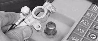
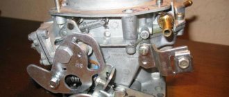
Remove the hood (see Replacing the hood) and the battery. Drain the oil (see Changing the oil). Drain the coolant (see Replacing the coolant). We remove the radiator together with the thermostat (see Replacing the radiator and Replacing the thermostat).
Remove the carburetor (see Replacing the carburetor). Remove the fuel pump (see Replacing the fuel pump). Remove the ignition distributor (see Replacing the ignition distributor). Having sketched the connection order, we disconnect the hoses and wires from the engine, lighten the cylinder block, for which we remove the cylinder head (see Replacing the cylinder head gasket). We remove the generator (see Removing the generator). Remove the starter (see Replacing the starter). Remove the coolant pump (see Replacing the coolant pump). We unscrew the upper or lower nuts securing the engine support cushion (see Replacing the engine support cushion). We unscrew the bolts securing the clutch housing to the engine.
We fasten the cables of the lifting device to the block and lift it. By placing a jack under the gearbox and slightly rocking the block, we disconnect the block and the clutch housing.
We install the cylinder block on the stand. Remove the clutch (see Replacing the pressure plate assembly and clutch release bearing). Remove the pulley, camshaft drive cover, oil pump drive chain and gear (see Replacing the camshaft drive chain). Remove the auxiliary drive shaft (see Replacing the auxiliary drive roller). Remove the flywheel and the rear crankshaft cuff holder (see Replacing the rear crankshaft cuff).
Using a 10mm wrench, unscrew the fourteen bolts securing the oil pan to the cylinder block.
. and remove it along with the sealing gasket.
Remove the oil pump (see Removing and disassembling the oil pump).
Using a 14mm socket, unscrew the two nuts securing the connecting rod cover.
. and remove the connecting rod cover.
Using the wooden handle of the hammer against the connecting rod, we push the piston out of the cylinder.
Similarly, remove the remaining three pistons.
Using a 17mm socket, unscrew the two bolts securing the crankshaft main bearing cover.
In the same way, remove the remaining four main bearing caps. They are marked with marks corresponding to their serial number (count from the toe of the crankshaft). On the last (fifth) cover there are two marks stamped, spaced along the edges.
Marks on the main bearing caps.
We remove the crankshaft.
From the grooves in the bed of the fifth main bearing, we remove two half rings of the crankshaft thrust bearing.
The steel-aluminum liners installed in the beds of the 1st, 2nd, 4th and 5th main bearings have a groove. The shell of the 3rd bearing does not have a groove (similar to the shells installed in the main bearing caps).
We disassemble the crankshaft (see Disassembling the crankshaft). We take out the old main bearing shells. We wash the cylinder block and crankshaft in diesel fuel or kerosene. We blow out their internal cavities and oil channels with compressed air. We wipe the seats of the main bearings with a napkin and install new liners of the appropriate category (nominal or repair). Lubricate the main and connecting rod journals of the crankshaft with engine or transmission oil and install the shaft into the block.
We install the main bearing caps with new bearings of the category corresponding to the crankshaft journals installed in them in accordance with the marks. Tighten the cover fastening bolts with a torque wrench (see Appendices).
Checking the rotation of the crankshaft. It should be light and smooth, without jamming or play. We install new steel-aluminum liners into the lower heads and connecting rod caps (see Replacing the piston).
Lubricate the piston, rings and cylinder walls with engine oil. We compress the rings with a special device and turn the piston with the “P” mark towards the toe of the crankshaft. With light blows of the wooden handle of a hammer on the bottom of the piston, we press it into the cylinder.
We put on the connecting rod cover and tighten the bolts with a torque wrench (see Appendix). Further assembly of the engine is carried out in the reverse order of disassembly.
Installation
1. Wash the crankshaft in kerosene and blow through its internal cavities with compressed air. We install new crankshaft main bearing shells of nominal or repair size. On the outer cylindrical surface of the liners there are numbers stamped indicating the repair size: 025 - the first repair, for the crankshaft journal, reduced in diameter by 0.25 mm. Accordingly, for the second, third and fourth repair sizes the values will be: 050, 075, 100. It is easy to distinguish connecting rod bearings from main bearings. The upper main bearings (except for the middle one) have annular grooves. In addition, the middle support liners are wider than the others. The connecting rod bearings are all identical and interchangeable, their diameter is less than the diameter of the main bearings. To increase the contact area, there are no annular grooves on the connecting rod bearings.
2. We install thrust half-rings in the grooves of the fifth main bearing with grooves towards the crankshaft. Half rings are manufactured in normal thickness (2.310-2.360 mm) and increased thickness (2.437-2.487 mm).
3. We check the axial clearance between the thrust half-rings and the thrust surfaces of the crankshaft, which should be in the range of 0.06-0.26 mm. If the gap exceeds the maximum permissible (0.35 mm), replace the thrust half-rings with new ones, increased by 0.127 mm.
4. Lubricate the connecting rod and main journals of the crankshaft with engine oil and install the shaft into the block.
5. In accordance with the marks, install the main bearing caps and tighten their mounting bolts to a torque of 68.4-84.3 Nm. Check the free rotation of the shaft.
6. Install connecting rods with liners and covers on the crankshaft. Tighten the fastening nuts to a torque of 43.4-53.5 Nm.
8. Install the holder with the oil seal on the cylinder block (see “Crankshaft rear oil seal - replacement”).
9. Installation of the remaining removed parts is carried out in reverse order.
12. On a carburetor engine, we check and, if necessary, adjust the ignition timing (see “Ignition timing - checking and adjustment”).
Sometimes a car requires very minor repairs, just replacing the liners, but is it really necessary to remove the engine, look for a hoist or several assistants for such a simple procedure? When it comes to such a need, replacing the liners without removing the engine will help. This simple type of repair does not require a large number of tools, but it does require some skill, so you should immediately evaluate your skills.
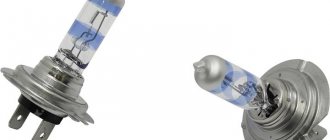
Piston repair: what you should pay attention to
Modern materials and technologies for manufacturing parts make it possible to operate the engine under very intense conditions. The maximum crankshaft rotation speed reaches one hundred revolutions per second. In this case, the piston and connecting rod reach a translational speed of up to 30 m/sec twice for each revolution (two hundred times per second). and the same number of times they come to a complete stop, causing huge cyclic inertial loads (the weight with such acceleration increases by more than a thousand times). Therefore, technologists try to make the piston as light as possible, making it from an aluminum alloy with a cast steel plate that compensates for thermal deformations. The piston has stiffening ribs and hard anodizing, up to the fire zone, which protects the bottom and the groove of the upper compression ring from burning out. Friction is reduced by the most advanced brands of oils with additives. But it is impossible to avoid wear, so periodically, after a certain mileage, the piston VAZ 2106 is replaced. It is better to do this when the first symptoms appear:
Operating a car with wear and tear can lead to damage that will require major repairs, which will increase the price many times over.
How to dismantle the piston yourself
First of all, it is necessary to thoroughly wash the engine, since after disassembly it will be difficult to prevent grains of sand and dirt from getting inside. The engine must be placed on a sturdy rack at a height convenient for work. Prepare rags, a set of tools and accessories:
- socket, ring wrenches and heads 10 mm., 12 mm., 13 mm., 14 mm., 17 mm., 19 mm., 22 mm., and wrench 36 mm.;
- a set of thin flat probes;
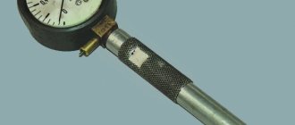
- bore gauge;
- micrometer;
- calipers;
- torque wrench;
- device for compressing rings on the piston;
- bushing for installing piston pins;
- gas-burner;
- hammer;
- core;
- portable lamp;
- large flathead screwdriver.
Tip: Before disassembling with your own hands, all parts are marked with a core, and a photo of the initial location is taken with the numbers and marks of the removable parts so that they can be installed in their place if they are suitable.
Disassembly sequence
- The engine with the head, pan and side covers removed is laid on its side to allow access to the pistons and connecting rods. Wrench 36 mm. the crankshaft is rotated to the position of maximum extension of the nuts of a pair of connecting rods.
- Using a head and a long wrench, you need to unscrew two nuts each, securing the connecting rod cap of the first and fourth cylinders, you can use any one, but it is more correct to follow the chosen sequence. By lightly tapping with a hammer, the cover moves out of place, allowing you to easily remove it from the studs. It is advisable to first familiarize yourself with the stages of work via video.
Tip: The caps and connecting rods form a pair; during their manufacture, the final boring of the mounting hole is done in assembled form, so they are marked with the cylinder number and cannot be replaced. You need to make sure that the numbers match when assembling and are directed in the same direction.
- Using the wooden handle of a hammer, resting against the pin, the connecting rod with the piston is pushed out through the upper plane of the cylinder block. The crankshaft is rotated to the maximum extension position of the nuts of the other two connecting rods. All four pistons are disassembled in the same way. The main bearings are unscrewed and the crankshaft is removed for visual inspection.
Why does this happen and how to avoid it?
- The lubricant was too viscous or there was too little of it. Abrasive got into the lubricant and disrupted the smooth running. Lubricant cleanliness is one of the key parameters for preventing any breakdown; it is better to change it regularly every 60-80 thousand km. mileage
- The motor was constantly operating in overload mode. You should not constantly “strain” the engine at high speeds and drive the car for a long time without slowing down.
- When installing previous bearings, the interference was too low. Check everything yourself, tighten the bolts well, it is better to use special equipment.
CRANKSHAFT ASSEMBLY. Installation of liners, half rings, bearing caps on vases of the classic family.
Crankshaft assembly
The next in line in the engine work section is a page with material describing the assembly of the crankshaft
How to select, repair and install a crankshaft on a VAZ 2106
I think there is no need to once again focus on the seriousness of this work. The crankshaft is assembled according to the sequence described below
Install the upper main bearing shells so that the installation lug of the liner is aligned with the recess in the cylinder block bed. Install bushings that do not have a groove and are larger in width into the bed and cover of the middle bearing.
Immediately after installing the liners in place, they should be lubricated with clean engine oil. Install the crankshaft into the cylinder block, install the lower bearings that do not have grooves into the main bearing caps. Lubricate the crankshaft journals with clean engine oil.
Install the main bearing caps, except the rear cover, in their places in accordance with the marks, since they were installed before disassembly.
Lubricate the thrust half-rings with clean engine oil. Install front steel-aluminum and rear metal-ceramic thrust half-rings on the rear crankshaft support.
In the image, the arrows show the recesses on the thrust half-rings. The thrust half-rings should be installed using notches
to the bearing surfaces of the crankshaft.
Install the cover on the rear main bearing and, using a torque wrench, tighten the cover bolts to the appropriate torque.
Using a flat feeler gauge, measure the axial clearance of the crankshaft; to do this, use a mounting blade to move the crankshaft until it stops. The axial clearance should be from 0.06 to 0.26 mm, the maximum clearance allowed is 0.35 mm. If the clearance exceeds the values, the above thrust half-rings are necessary replace with new ones, increased by 0.127 mm.
- On which journals does the crankshaft rotate in the engine?
Turn the crankshaft a certain number of revolutions, if the shaft rotates smoothly without getting stuck, the shaft is assembled correctly. Having aligned the installation tab of the liner with the notch on the connecting rod, insert the liners and connecting rods, connecting rod bolts.
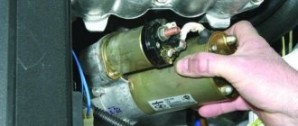
How to replace bearings without removing the engine?
Many car owners think and write on forums that it is impossible to get to the liners without removing or removing them from the engine hood. However, such operations are carried out by repairmen on ships, where the size of the parts is enormous and too much force is required to remove the engine. And if the technique exists, it can be used for simple cars.
- Park the vehicle on a ramp to gain easy access to the engine. If there is protection installed on it, it should be removed and the lubricant drained.
- Remove the box, front cover and loosen the camshaft chain in advance. If you're not too lazy, it's better to remove it entirely so it doesn't interfere.
- Remove the starter and pan (if the beam does not interfere). If it interferes with operation, you will have to lift the motor and pull out the pan from under it.
- You now have access to the crankshaft. The easiest way is to replace the connecting rod bearings. The old bearings are pulled out after unscrewing the head screws; it’s easy to put new ones in place, just don’t forget to lubricate them well with the same engine oil that is in your engine.
- It is more difficult to replace the main bearings without removing the engine. You will need to lower the crankshaft by loosening its fastening. You don’t need to lower it much, ten, maximum fifteen centimeters.
- Now it will be easier to pull out the earbuds. But you will need an aluminum rivet, which must be inserted into the lubrication hole, so it will push the bearing out. The main thing is that the size of the rivet is suitable and does not scratch the crankshaft.
If the pressure in the lubrication system decreases or dull noises appear when the VAZ 2106 engine is running, the reason may be a faulty crankshaft. The article discusses the causes of malfunctions, as well as how to change the crankshaft of a VAZ 2106. In addition, a video is attached that demonstrates the partial assembly of a VAZ engine with the installation of the crankshaft.
Installing the VAZ engine block head
Before you start installing the head, you need to lift the chain by hand and place a mark on the pulley, the mark is placed in front of the long mark on the cover, this is the top dead center.
Then we put the chain on the shoe, be sure to perfectly clean the upper part of the engine from stuck pieces of the old gasket, do not forget about the cylinder head, it also needs to be cleaned. We put the head gasket on the block, then you immediately need to put the muffler gasket on the manifold, put the head on the block, then put the manifold on the muffler. We tighten our heads. As you tighten the head bolts, go over them a couple of times, alternately turning each of them a little, this should be done in order to tighten it as much as possible. The camshaft must be chosen carefully, it is best to buy a factory one, the factory one is sold in a box, but there are also fake ones, they are sold without a box, it is usually wrapped in paper, and the factory one should also have a limiter.
If the camshaft does not sit tightly in the bed, it means it is loose and loose; to find out, you will need to knock on the bed.
Now we take the wire in our hands and make a hook, with this hook we take out the chain, thread the wire into the chain, do everything carefully, as the chain may fall into the engine block.
We loosen the chain tensioner, then using a pry bar you need to press the shoe all the way, then we tighten the tensioner, thanks to this we can easily put the chain with the sprocket on the camshaft.
We take the camshaft sprocket, put a chain on it, the sprocket mark should be at the very top. We place the sprocket on the camshaft, and check the position of the chain mark; when the chain is tensioned, the mark should coincide with the mark on the camshaft, with the mark on the crankshaft pulley. After installing and checking the marks, be sure to tighten the camshaft sprocket securely.
There are cases when the marks on the pulley and the camshaft do not match, it may turn out that one mark does not go much forward or backward, it is better if the mark does not reach the mark on the camshaft a little. After you have set the marks, you can tension the chain.
Symptoms of a problem
If you repair the crankshaft yourself, you can save a lot on car service costs. Therefore, it is worth understanding its diagnosis, repair and installation. If repairs are not carried out in a timely manner, the engine may seize, and this can lead to more serious repairs. The following are signs that serve to identify malfunctions:
- when the engine is running, the oil level control light does not go out, which indicates a decrease in oil pressure in the system;
- at medium and high speeds a metallic knock is heard in the engine, which increases with increasing speed;
- engine jams.
The cause of the first two malfunctions is the wear of the main and connecting rod journals. In this case, the distance between the neck and the liner increases, which leads to a decrease in oil pressure. If the distance is too large, the shaft may run out, causing metallic sounds in the engine. If the engine jams, it is better to replace the crankshaft. To diagnose the serviceability of the crankshaft, it should be dismantled and cleaned. It is better to remove the part together with the engine.
After removal, you need to perform a visual inspection of the necks and cheeks, according to which a decision is made on the need for grinding or replacement. No special instruments are needed for inspection; you can tell by touch. If scratches and burrs are found on the journals, the part is sent for boring. Boring can be done 4 times. Each boring increases the dimensions of the liners by 0.25 mm. After dismantling the crankshaft, you need to evaluate the size of the liners and whether they will allow boring. If grinding has never been performed, then the liners have an icon without any numbers.
If cracks are found, the crankshaft must be replaced. You can send it for welding, but usually restored parts last no more than 50 thousand kilometers. After boring, you need to polish the journals. Then the journals and crankshaft need to be washed with gasoline. The oil passages should also be thoroughly cleaned to prevent contamination from entering the bearings. After washing with gasoline, you need to blow out the oil channels using compressed air.
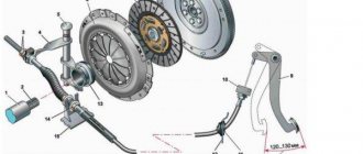
How to select and replace crankshaft bearings with your own hands
Every detail is important for the smooth operation of a car engine. A special position in the crank mechanism system is occupied by the crankshaft liners. Thin semicircular steel-aluminum plates surrounding the main and connecting rod journals are the outer races of the plain bearings, and the overall performance of the engine depends on their condition.
When is it necessary to replace crankshaft bearings?
Under the conditions of the physical and thermal loads that the crankshaft has to endure, only plain bearings can keep it on the axis and ensure the operation of the crank mechanism. The main and connecting rod journals serve as internal races, and the liners, respectively, serve as external races. The engine block system has a network of oil lines through which engine oil is supplied to the liners under high pressure. It creates a thin oil film that reduces friction and allows the crankshaft to rotate.
Physical wear is the first and main condition due to which the liners have to be changed. No matter how much we would like to avoid wear, the surfaces of the journals and bearings are gradually worn away, the gap between them increases, the crankshaft becomes free to move, and the oil pressure drops sharply. All this leads to engine breakdowns.
Another reason for forced repairs is a situation where the crankshaft liners rotate. Every car owner has heard about such malfunctions, but not everyone knows how and why this happens. A thin plate of the liner is placed in the so-called bed. On the outer walls of the half rings there are special antennae (protrusions), which, after assembly, rest against the end parts of the block or bearing cap.
Sometimes, when certain conditions occur, the antennae are not able to hold the liner and it sticks to the crankshaft journal and rotates. If the crankshaft liners are turned, the engine cannot run. Typical causes of such a breakdown:
- too viscous lubricant, lack of it, abrasive ingress;
- too little interference when installing bearing caps;
- insufficiently viscous lubricant and operation of the motor in overload mode.
Selection of crankshaft liners
Whatever the reasons why the car owner is forced to disassemble the engine and change the liners, grinding the crankshaft is indispensable. New liners are installed either on a new crankshaft or after grinding it. Even if only one neck is damaged or worn, all of them undergo grinding to the same size.
At the factory, when assembling the motor, standard liners are installed. For VAZ engines, liners are available in 4 repair sizes. Accordingly, grinding the crankshaft can be carried out no more than 4 times. The step between sizes is 0.25 mm. Accordingly, after the first grinding it is necessary to buy inserts marked “0.25”, after the second - 0.5, after the third - 0.75, after the fourth - 1.0. Motors that are installed on GAZ and Moskvich cars have two more borings available, up to 1.25 and 1.50 mm.
The dimensions of the crankshaft liners that need to be purchased can only be calculated by a specialist who grinds the crankshaft. Sometimes it happens that damaged necks require grinding not to the next size, but after one. Inserts are sold only as a set for all main or connecting rod journals.
How to replace crankshaft bearings with your own hands
Considering that to access the crankshaft you will have to completely disassemble the engine, such repairs can only be started if the car owner has the necessary knowledge and skills in this matter. First of all, you need to remove and completely disassemble the motor. This can be done in a garage, but it requires a full set of car keys and other tools, as well as a mechanical winch. To remove the motor, do the following:
- remove the hood and battery;
- drain the oil and coolant;
- remove the engine from attachments: carburetor, starter, generator, fuel pump and cooling system pump, ignition distributor, remove the radiator and cylinder head;
- then unscrew the clutch cover, the nuts of the pillows and remove the block;
- Having placed the engine on the workbench, you should remove: the flywheel, pulley, camshaft drive cover, oil pump drive chain and gear, auxiliary drive shaft, flywheel, and rear cuff holder;
- after the 14 bolts of the pan are unscrewed, the crankshaft itself will become available to us;
- in order to remove it you will need to unscrew the bolts of the five main bearing caps and the bolts of the four connecting rod caps.
By removing the bearing caps, you can immediately notice where the bearings have rotated. It is strongly recommended that you do not remove the covers or remove the crankshaft until it has been seen by a professional. Based on the characteristic signs of uneven wear, a specialist will be able to determine where the displacement or curvature has occurred. To do this, it is necessary that each liner remains in its place.
Crankshaft installation process
Before installing the crankshaft on the VAZ 2106, you need to wash, clean and dry the cylinder block. And only after that read the process.
Tools
To complete the installation you will need the following tools:
- a set of keys;
- Screwdriver Set;
- micrometer;
- consumables (liners, seals, half rings);
- torque wrench.
If defects in the form of scratches, burrs, or signs of wear are found on the surface of the liners, they must be replaced. The earbuds cannot be adjusted. When using the removed bearings further, you need to check the gap between them and the main and connecting rod journals of the crankshaft. For main shafts, the permissible size is 0.15 mm, for connecting rods - 0.10 mm. If the dimensions exceed the permissible limits, the liners are changed to a greater thickness after boring the necks. If the journals are properly ground and the appropriate bearings are selected, the crankshaft should rotate freely.
The oil seals that ensure the tightness of the crankshaft are replaced regardless of how long they have been standing. Half rings, like liners, cannot be adjusted. If burrs and scratches are found, the half rings are replaced. They are also changed if the axial clearance of the crankshaft is greater than the maximum permissible, which is 0.35 mm. The selection of new rings is carried out according to the nominal thickness or with a thickness increased by 0.127 so that the axial clearance is in the range of 0.06-0.26 mm.
Stages
Installation of the crankshaft on the VAZ 2106 is carried out in the following sequence:
- First, the support bearing of the input shaft is pressed in.
- Next you need to install new liners. The main liners are installed to the required repair size. The connecting rods are the same size, so they are interchangeable. When installing, you need to be careful not to mix up the bearings. The connecting rod bearings are smaller in diameter than the main bearings and do not have annular grooves.
- Then you need to install the thrust half rings into the bed of the 5th main bearing. In this case, the grooves should be directed towards the crankshaft. Half rings are selected according to tolerances.
When installing gaskets, you should use a sealant to ensure reliable sealing and prevent leakage of working fluids during further operation of the vehicle.
After final assembly, you need to start the engine and check its performance.
Thus, even a driver with little experience in repair work can perform crankshaft repairs on a VAZ 2106, and you can significantly save on car service costs.
Why is a crankshaft needed in a VAZ 2106 engine?
The crankshaft (crankshaft) is an important part of the crank mechanism of any engine. The operation of the unit is aimed at converting the energy of combustion gases into mechanical energy.
Description of the VAZ 2106 crankshaft
The crankshaft has a rather complex design, with connecting rod journals located on the same axis, which are connected through special cheeks. The number of connecting rod journals on the VAZ 2106 engine is four, which corresponds to the number of cylinders. Connecting rods provide connection between the journals on the shaft and the pistons, resulting in reciprocating movements.
Let's look at the main elements of the crankshaft:
- Main journals are the supporting part of the shaft and are installed on main bearings (located in the engine crankcase).
- Crankpins. This part is designed to connect the crankshaft to the connecting rods. The connecting rod journals, unlike the main ones, have a constant displacement to the sides.
- Cheeks are a part that provides connection between two types of shaft journals.
- Counterweights are an element that balances the weight of connecting rods and pistons.
- The front part of the shaft is the part on which the pulley and timing gear are mounted.
- Rear end. The flywheel is attached to it.
Seals are installed in front and behind the crankshaft - oil seals, which prevent oil from escaping out. The entire crankshaft mechanism rotates thanks to special plain bearings (liners). This part is a thin steel plate that is coated with a low-friction material. To prevent the shaft from moving along the axis, a thrust bearing is used. The material used in the manufacture of the crankshaft is carbon or alloy steel, as well as modified cast iron, and the production process itself is carried out by casting or stamping.
The crankshaft of the power unit has a complex structure, but the principle of its operation is quite simple. In the engine cylinders, the fuel-air mixture ignites and burns, resulting in the release of gases. During expansion, the gases exert an impact on the pistons, which leads to translational movements. Mechanical energy from the piston elements is transferred to the connecting rods, which are connected to them through the bushing and piston pin.
An element such as a connecting rod is connected to the crankshaft journal using a liner. As a result, the translational movement of the piston is converted into rotation of the crankshaft. When the shaft makes a half revolution (turns 180˚), the connecting rod journal moves back, thereby ensuring the return of the piston. Subsequently, the cycles are repeated.
No less important in the operation of the crankshaft is the process of lubrication of rubbing surfaces, which include the connecting rod and main journals. It is important to know and remember that lubricant is supplied to the shaft under pressure created by the oil pump. Oil is supplied to each main journal separately from the general lubrication system. Lubricant is supplied to the connecting rod journals through special channels located in the main journals.
Neck sizes
The main and connecting rod journals wear out as the engine operates, which leads to disruption of the proper operation of the power unit. In addition, wear can be associated with various types of engine problems. These include:
- low pressure in the lubrication system;
- low oil level in the crankcase;
- overheating of the engine, which leads to oil dilution;
- low quality lubricant;
- severely clogged oil filter.
The listed nuances lead to damage to the surface of the shaft journals, which indicates the need for repair or replacement of the unit. To assess the wear of the journals, you need to know their dimensions, which are shown in the table.
Table: crankshaft journal diameters
| Connecting rod | Indigenous | ||||||||
| Nominal | Repair | Nominal | Repair | ||||||
| 0,25 | 0,5 | 0,75 | 1 | 0,25 | 0,5 | 0,75 | 1 | ||
| 47,814 | 47,564 | 47,314 | 47,064 | 46,814 | 50,775 | 50,525 | 50,275 | 50,025 | 49,775 |
| 47,834 | 47,584 | 47,334 | 47,084 | 46,834 | 50,795 | 50,545 | 50,295 | 50,045 | 49,795 |
What to do when necks wear out
What are the steps to take if the crankshaft journals are worn out on a VAZ 2106? First, the defectiveness is carried out, measurements are taken using a micrometer, after which the crankshaft journals are polished using special equipment to the repair size. This procedure cannot be done in a garage environment. The necks are ground to the closest size (based on the tables provided). After processing, thickened liners (repair) are installed in accordance with the new size of the necks.
If a major overhaul of the engine is being carried out, it would not be superfluous to inspect the oil pump, blow out the oil passages of the cylinder block, as well as the crankshaft itself. Attention should be paid to the cooling system. If there are signs of wear or damage on the engine elements or its systems, the parts and mechanisms need to be repaired or replaced.
Video: grinding the crankshaft on a machine
Crankshaft selection
The need to select a crankshaft for a VAZ 2106, like for any other car, arises in case of engine repair or to improve engine performance. Regardless of the task at hand, it must be remembered that the crankshaft must be heavy, with large counterweights. If the part is selected correctly, mechanical losses will be significantly reduced, as well as other loads on the mechanisms.
In the process of selecting a unit, even if it is new, close attention is paid to its surface: there should be no visible flaws, such as scratches, chips, or burrs. In addition, attention is paid to a number of crankshaft characteristics, namely coaxiality, ovality, taper and journal diameter. During engine assembly, the crankshaft is balanced to balance all rotating elements. A special stand is used for this procedure. Once balancing is completed, secure the flywheel and continue the process again. Afterwards, the clutch basket and other elements (pulleys) are mounted. There is no need for balancing with the clutch driven disc.
Video “Assembling the engine of a classic VAZ car”
This video demonstrates the procedure for assembling an engine on a VAZ classic, including installing the crankshaft.
The crankshaft is the most important part of internal combustion engines with a crank mechanism. The health of the entire engine directly depends on its condition. A power unit with a worn crankshaft does not develop full power, and the oil pressure in such an engine is low even at rated speed, not to mention idle.
The VAZ 2106 crankshaft, the wear of which exceeds the permissible level, will not be able to operate reliably. Therefore, in order to prevent the engine from jamming, this part is removed and repaired.
Engine assembly VAZ 2101 to 2107
We continue to do a major overhaul of the six engine. Spare parts have been purchased, the block and crankshaft have been bored out. It seems like a trifle, just take it and assemble the engine yourself at home, saving money on the mechanic.
But, I had to remake a lot of engines after homemade ones, and stupid motorists.
Therefore, in this article I will try to explain how to properly assemble the engine, taking into account all sorts of little things, since without taking these little things into account, the engine will not work for a long time.
I start assembling the engine by installing the crankshaft, here there are a lot of little things that need to be taken into account.
When assembling the engine, you can wash it well, or you don’t have to, but the main thing is that everything inside the engine is clean, but I got greedy and basically don’t wash the outside of the engine, and everyone knows that. My only advice is that after repairing the engine, go to a car wash and wash the engine from above, if you wish.
On the other hand, I like the moment when the owner comes to pick up the car after repairs, opens the hood and sees a grimy engine, makes a face, but after starting it, breaks into a satisfied smile.
Before installing the crankshaft, you need to install the main bearings in the engine block bed; be sure to wipe the bearing beds clean with a rag before installing the bearings. So that there is not a single speck between the liner and the bed. The photo shows how to correctly install the inserts in the engine block.
Photo. Correct installation of liners in the VAZ engine block.
After installing the liners, be sure to lubricate them with oil.
Photo. Installed thrust half-rings (crescents)
And just before installing the crankshaft, install thrust half-rings (half-moons) into the block so that they do not fall and lubricate them with oil. Carefully place the crankshaft on the bearings and make sure that the crescents do not fall off.
I usually install crescents with brass plating, but if you have one crescent with brass plating and the other with aluminum, then install it with brass plating on the flywheel side.
Photo. Checking the longitudinal stroke of the crankshaft.
After installing the crankshaft, be sure to check the longitudinal stroke of the crankshaft. Usually I ensure that the longitudinal stroke of the crankshaft is zero, or a maximum of one tenth of a millimeter. You can check the longitudinal stroke of the crankshaft by inserting a screwdriver between the crankshaft cheeks from different sides. If you do not take into account the longitudinal stroke of the crankshaft, and the stroke is large, then the crescents will fall out, the crankshaft will dangle longitudinally in the engine, when you press the clutch, it will rest against the engine block and gnaw the metal in the block. Since I have been doing repairs for a long time, I have a whole bunch of working and new crescents; they also sell special repair crescents, they are thicker than standard ones. Therefore, it is easy for me to select crescents so that there is no longitudinal movement of the crankshaft. If, after installing standard crescents, there is longitudinal movement in the crankshaft, buy repair crescents, but it often happens that the crankshaft does not fit on the repair crescents, then try placing one working crescent and the other a repair one, or carefully grind off the excess metal from the repair crescent on a grindstone.
Photo. Checking the crankshaft for tightness.
After the crescents are selected, insert the liners into the cushions and attach them to the crankshaft, but do not tighten them too much right away, insert the key onto the crankshaft and start tightening one cushion at a time, and after tightening the next cushion, try to rotate the crankshaft. Details of checking and adjusting the liners can be found on the Crankshaft Repair page.
Photo. The connecting rod and piston are prepared for knocking out the pin.
Signs of a bad crankshaft
There are several signs that can directly or indirectly indicate a crankshaft malfunction:
- when the engine is running at low speeds, the oil pressure indicator light comes on;
- when operating at medium and high speeds, a metallic knock can be clearly heard, the frequency of which increases with increasing speed;
- engine jamming.
In the first two cases, the cause of the malfunction is the wear of the connecting rod or main journals of the crank. The increased gap between the surface of the journal and the liner is what causes a drop in oil pressure. With a critically large gap, the shaft may run out, which causes knocking (the engine “knocks”). The third case is the most difficult. Only a small portion of crankshafts from seized engines can be repaired. In most cases, the crankshaft will need to be replaced.
When and why to change the front oil seal
The manufacturer recommends replacing the front crankshaft oil seal of VAZ 2101-2107 engines every 150,000 km. However, in practice such replacement has to be performed more often. Accelerated wear of the sealing element and the appearance of engine oil leaks are caused by:
- skewed oil seal during installation;
- loss of elasticity due to engine overheating;
- increased radial runout of the drive pulley of mounted units;
- use of low-quality motor oil;
- wear on the crankshaft pulley hub.
In addition, we cannot rule out hardening of the cuff due to natural aging and the possibility of a manufacturing defect - unfortunately, the quality of parts for rear-wheel drive VAZ models leaves much to be desired.
It is impossible not to notice damage to the sealing element - the rotating pulley scatters oil in the front of the engine and throughout the engine compartment. However, do not think that such a malfunction only leads to oiling of the units and a decrease in the lubricant level. If engine oil gets on the generator belt and other rubber parts, it can quickly render them unusable.
Keep in mind that the appearance of a leak through the engine seals is provoked by another factor - increased crankcase gas pressure. For this reason, be sure to check the cleanliness of the engine ventilation system.
Crankshaft repair
The crankshaft removed from the vehicle is thoroughly cleaned and inspected. The presence of cracks on the main and connecting rod journals, as well as on the cheeks, is not allowed. If they are found, the crankshaft can be submitted for welding, but it would be better to replace it. Typically, restored crankshafts do not last more than 50 thousand km. They also check for the presence of deep grooves, burrs, scratches and nicks at the contact point of the VAZ 2106 crankshaft oil seal.
To determine the runout, as well as the displacement of the axes of the connecting rod journals, the crank is mounted on prisms. The values of radial runout, axial displacement and non-perpendicularity of the flange end to the crankshaft axis are measured. If the permissible parameters are exceeded, a decision is made to replace the part or edit it using a hydraulic press. Let us immediately note that the VAZ 2106 crankshafts are made of cast iron, so attempts to correct its geometry with a press often end in part failure.
Next, measurements are taken of the parameters of the journals (connecting rod and main). When they are produced to a size that is 0.005 mm less than the minimum allowable (for this repair size) and (or) their ovality is exceeded by more than 0.05 mm, a decision is made whether grinding and replacement of the crankshaft liners is necessary. The journals must be ground to the closest size (according to the repair size chart). The center-to-center distance between the main and connecting rod journals should ensure a piston stroke from 79.9 mm to 80.05 mm.
Crankshaft device
The crankshaft consists of flat machined plates with counterweights (the so-called “cheeks”), which are connected to each other by “necks”. Counterweights are needed to dampen the reciprocating movements of the pistons and stabilize the rotation of the shaft.
Crank mechanism with an additional block of balancers
In V-twin and W-twin engines, connecting rods from opposing cylinders press against interconnected journals. This allows for more uniform operation of the engine and reduces its dimensions. In in-line engines, each connecting rod is mounted on a separate journal with balancers.
Crank mechanism of an inline four-cylinder engine with standard journals and balancers
V6 engine crankshaft with forked adjacent crankpin
The crankshaft journals are cylindrical in shape with a ground surface. The main journals are located along the axis of the shaft, and the “crank journals” are located along the axis of the connecting rods. The rubbing pairs of the crankshaft are usually mounted on plain bearings. To prevent longitudinal displacement of the shaft, support bearings are provided, they are also called crankshaft half rings.
The crankshaft is located in the cylinder block in the reciprocal seats of the “crankshaft bed”. On the crankshaft there is a shank for fastening the timing sprocket, generator pulley and water pump. On the back of the shaft there is a flange for fastening the flywheel. A rolling bearing is installed in the flange, and the gearbox input shaft fits into it. Inside the crankshafts there are channels for forced lubrication of the journal liners, connecting rods and cylinder-piston group. The design of crankshafts depends on the layout of the cylinders and their number. Drive gears for various equipment, such as an oil pump, can be installed on the crankshaft.
Crankshaft device
Installing the crankshaft
The crankshaft is installed on a pre-washed, dry and clean block. Assembly is carried out in the following sequence:
- Press in the support bearing of the input shaft.
- Install new crankshaft main bearings.
- Crankshaft half rings are selected according to the tolerance parameters.
- The connecting rod and main journals are lubricated with engine oil, after which the crankshaft is placed in the block.
- Place the bearing caps according to the marks and tighten the fastening bolts with a force of 68-84 Nm.
- Next, the connecting rod bearings are installed and the connecting rods are secured. The bolts must be tightened to a force of no more than 54 Nm.
- Install the rear crankshaft oil seal.
- The unit's oil pan is attached to the block.
- The front oil seal is installed on the block together with the cover (replacing the crankshaft oil seal is necessary after grinding in any case).
- The crankshaft pulley is installed after tightening the front cover.
- Next, the intermediate shaft is mounted on the engine, the cylinder head and gas distribution mechanism parts are installed.
- Adjust the chain tension.
- Place marks on the crankshaft and marks on the camshaft.
- The remaining parts and components are installed.
- Adjust the tension of the generator belt.
- Install and regulate the ignition.
During assembly, all gaskets must be sealed with automotive sealant. This way you can avoid oil leakage during operation of the unit.
You can't decide whether to repair or change the crankshaft? The price for a new one is currently at least 3,000 rubles. If you grind and repair an old VAZ 2106 crankshaft, the price of the work will be 5 times less than this amount, so the benefit is obvious.
The crankshaft and photos of the stages of its repair, reading specialized literature - all this will help you approach the work with confidence, breathe new life into the engine with your own hands, and grow in the eyes of friends and acquaintances.
The VAZ 2106 crankshaft is a part of the crank mechanism that plays a very significant role in the car. In order to install the crankshaft as efficiently as possible, you will need a wide variety of tools, most of which are sold at any specialized automotive store. Please note that when assembling the piston of VAZ 2106 connecting rod engines there are some peculiarities.
Crankshaft pulley
The generator and water pump on the VAZ 2106 are driven by a belt from the crankshaft pulley. When carrying out repair work on the engine, attention should also be paid to the condition of the pulley: is there any visible damage (cracks, scuffs, dents). If defects are found, the part should be replaced.
During the installation process, the pulley should sit smoothly on the crankshaft, without distortion. Despite the fact that the pulley fits quite tightly on the shaft, a key is used to prevent rotation, which can also be damaged. A defective part must be replaced.
Crankshaft marks
In order for the engine to work flawlessly, after installing the crankshaft, the correct ignition setting is necessary. There is a special casting on the crankshaft pulley, and on the cylinder block there are three marks (two short and one long) corresponding to the ignition timing. The first two indicate an angle of 5˚ and 10˚, and the long one - 0˚ (TDC).
The mark on the crankshaft pulley is located opposite the length of the marks on the cylinder block. There is also a mark on the camshaft sprocket that must be aligned with the casting on the bearing housing. To rotate the crankshaft, use a special wrench of the appropriate size. According to the marked marks, the piston of the first cylinder is at top dead center, while the slider on the ignition distributor must be installed opposite the contact of the first cylinder.
Despite the fact that the crankshaft is a critical component of any engine, even a novice auto mechanic can repair the mechanism, with the exception of the grinding stage. The main thing is to select the elements according to the dimensions of the shaft, and then follow the step-by-step instructions for assembling it.
We remove the crankshaft to replace it or replace the bearings.
Replacing the crankshaft oil seal
In particular, a signal that an urgent replacement of the front oil seal liners is necessary is the direct contact of oil on the pulley and its further splashing in the front part of the engine. If oil leaks in the rear oil seal, splashing occurs on the flywheel in the clutch housing. Reasons for replacement:
You can replace crankshaft oil seals yourself; this will not only significantly save time and money spent on repairs in the workshop, but also gain invaluable experience. Replacing the crankshaft oil seal is a standard procedure to ensure optimal engine performance.
According to statistics, the installation of a new oil seal should be done at least once every 3 years. However, oil seal bearings may need to be replaced much sooner. It all depends on the general condition of the parts and the conditions under which the car is used.
Selection of crankshaft liners
In most cases, the selection is entrusted to a specialist. But after studying the information in detail, you will be able to do this on your own. In addition to the fact that it is necessary to combine spare parts with the car model, the general condition of the vehicle is also taken into account.
Selection of main liners
Some useful recommendations for selecting a new HF when replacing the crankshaft liners:
- it is better to buy basic elements of the same color as the standard ones (used, old);
- Be sure to check the markings directly on the shaft.
A special identification color selection card is issued for main bearings. For example, for a 4-cylinder engine, the markings applied to the BC and the CV assembly are used. If marked C3, then you can install yellow and green elements. More details about the colors in the picture below.
And this is an identification card for 6-cylinder engines.
Selection of connecting rod bearings
And here, if the HF is new, the plain bearings are selected according to the diagram. If the color code is lost, you need to look at the markings on the connecting rod caps.
Below is an identification card for selecting connecting rod half rings for four-cylinder power units.
And this is the color map for 6-cylinder units.
The choice of bearings also depends on the antifriction coating. As a rule, it consists of several layers:
- biometallic with a steel base (1-4 mm) - lead, copper, zinc, tin, silicon and aluminum;
- trimetallic - lead, tin, copper.
Use the correct engine oil that meets all the requirements and approvals of the engine manufacturer. It is also necessary to update the filter promptly to prevent abrasive particles from entering the lubricant. It is also not recommended to overload the engine. All this will extend the service life of the liners by almost 2-3 times.
Preparation for replacing bearings and direct installation of the crankshaft
In addition, disconnect parts such as the generator, starter, coolant pump, upper nuts that secure the engine mount, and bolts that secure the clutch housing to the engine. The order in which disconnection is made must be strictly observed. During operation, the lifting device cables must be secured to the block and carefully lifted.
Using a 10mm wrench, you need to unscrew all the bolts that secure the oil pan to the cylinder block and remove it along with the seal gasket. Disconnect the oil pump. Using a 14mm socket, unscrew the nuts that secure the connecting rod cover, and then remove it. Then take a hammer, press the handle against the connecting rod, and push the pistons out of the cylinders. Next, take a 17mm socket and unscrew the bolts that attach the crankshaft to the cover. Counting from the crankshaft toe, according to the number marks, we disconnect all subsequent covers. Keep in mind that on cover 5 there are two marks on both sides.
Examples of semirings
- Semiring ⟨N,+,⋅⟩{displaystyle langle mathbb {N} _{0},+,cdot rangle } .
- Trivial semiring: ⟨{},+,⋅⟩{displaystyle langle lbrace 0rbrace ,+,cdot rangle }
- Two-element semirings: ⟨Z2,+,⋅⟩{displaystyle langle mathbb {Z} _{2},+,cdot rangle }, ⟨B,⊕,∨⟩{displaystyle langle mathbb {B} ,oplus ,vee rangle }, where ∨{displaystyle vee } denotes , and ⊕{displaystyle oplus } denotes the logical operation “” on the set B={,1}{displaystyle mathbb {B} =lbrace 0,1rbrace }
- Square n×n{displaystyle ntimes n} with elements from the semiring N{displaystyle mathbb {N} _{0}} and operations of matrix addition and multiplication. Also, a semiring is formed by square matrices with elements from any semiring.
- If A{displaystyle A} is a commutative monoid, then the set End(A){displaystyle operatorname {End} (A)} A{displaystyle A} forms a semiring, where addition is defined pointwise and multiplication is defined as a composition of functions.
- Nx{displaystyle mathbb {N} } - with natural coefficients - form a commutative semiring; is a free commutative semiring with a single generator {x}{displaystyle {x}}.
- Probability semiring - non-negative real numbers with the usual operations of addition and multiplication.
- (max,+){displaystyle (max ,+)} and (min,+){displaystyle (min ,+)} are semirings of real numbers in which addition is defined as taking the maximum (respectively minimum), and multiplication is defined as ordinary addition real numbers.
The final stage
To secure, apply light blows with the handle of a hammer to the bottom of the piston, thereby pushing it into the cylinder. Screw on the second to fifth main bearing caps so as not to create a significant tightening. After this, purchase an odorless sealant from the store and apply a thin layer of it to the surface of the cylinder block in the place where it will come into contact with the first bearing cap.
After this, install a new sealing ring on the crankshaft and, after checking the location of the chain on the crankshaft sprocket, install the oil pump and pan. Also screw the removed cylinder head back into place, because only after this the structure can be completely assembled and the crankshaft considered replaced.
Source
Cold method of pressing a finger into a VAZ connecting rod. Video
The crankshaft has been installed, now we need to knock out the old pistons and install new repair pistons on the connecting rods. It is good to knock out the piston pins on a stump; drill a hole in the stump in advance, or knock it out with a chisel; the piston pin will be knocked out into this hole. It is advisable to knock out the finger with a special beard, or a round piece preferably with a diameter of 21 mm, and a heavy hammer. The piston pins are knocked out when cold; there is no need to heat them up.
Photo. Preparing pistons for installation on connecting rods.
Now we need to install new pistons on the connecting rods, you can install the pistons as is without modification, but I advise you not to be lazy and modify the pistons. First, chamfer the skirt using a sharpener or a file as shown in the photo, second, drill a hole in the piston skirt on both sides as shown in the photo.
Engines with modified pistons are much faster and more economical, since oil flows through the hole between the piston and cylinder skirt and reduces friction. Also, modified pistons do not suffer much if the engine accidentally overheats. The hole in the piston skirt used to be drilled 6mm, now it’s 14mm, so with a 14mm hole the engine turns out even faster.
Photo. A piston with a connecting rod, arrow 1 shows the front of the piston (letter P), arrow 2 shows the liner locks.
The photo shows how the piston should be positioned correctly on the connecting rod. You can drive your finger into the connecting rod while it’s hot, but here you don’t need to heat the connecting rod too much; it’s enough to heat it even in water to boiling water. Also, when the connecting rod is heated, you need to hammer in the piston pin very quickly, since if you hesitate a little, the pin will immediately take over the heating of the connecting rod and will become difficult to clog. I hammer it on a cold one, also on a stump, but I put a piece of a wooden block under the piston in the area of the piston pin, lubricate the pin and the hole in the connecting rod with oil, and also hammer the pin into the connecting rod with a heavy hammer. After hammering in the finger, be sure to check so that the finger is positioned exactly in the center and does not come out of the piston under any circumstances.
Photo. Installation of piston rings.
Next, we install the piston rings on the piston, I do it this way: I open the ring with my thumbs and hold it with my index fingers. Before installing new piston rings, practice on the old ones so as not to break the new ones. Be sure to look at how to install the piston rings; there are usually instructions on the packaging. But if not, then the inscription on the TOP ring says that this is the top of the ring, the oil scraper ring is the widest (but the German oil scraper ring consists of three parts), the second ring is cast iron, and the very first one is trussed at the top.
How to select and replace crankshaft half rings?
Over time, the thrust half rings, like any plain bearings, wear out, resulting in an increase in the axial play of the crankshaft. The working play (clearance) of the crankshaft lies in the range of 0.06-0.26 mm, the maximum, as a rule, should not exceed 0.35-0.4 mm. Large backlash can cause intense wear of crankshaft parts, squeezing out the crankshaft oil seal, increased oil consumption and a drop in engine power characteristics. This parameter is measured using a special indicator mounted on the end of the crankshaft. If the play exceeds the maximum permissible, the thrust half-rings must be replaced.
When choosing half rings, it is necessary to take into account an important nuance: not only the half rings are subject to wear, but also the thrust surfaces of the crankshaft. Therefore, in new engines, when the crankshaft clearance increases, it is usually necessary to change only the worn half rings - in this case, it is necessary to purchase parts of the nominal size. And in engines with high mileage, wear on the crankshaft thrust surfaces becomes noticeable - in this case, it is necessary to purchase thrust rings of a repair size.
It is necessary to select new half rings of the same types and catalog numbers as the old ones
It is important that they fully comply with the installation dimensions and have an appropriate anti-friction coating. The latter circumstance is especially important for motors in which semi-rings with different antifriction coatings are initially installed.
For example, on many VAZ engines, the rear semi-ring is cermet, and the front half-ring is steel-aluminium, and they are not interchangeable.
Replacement of half rings should be carried out in accordance with the instructions for vehicle maintenance and repair. On some engines, this requires removing the pan and dismantling the lower thrust bearing cover; on other engines, more serious disassembly will have to be performed. When installing new rings, their orientation must be observed - the anti-friction coating (which usually has grooves) must be installed towards the crankshaft cheeks.
With the correct selection and installation of half rings, thrust bearings will ensure normal crankshaft play and reliable operation of the entire engine.
Types and design of crankshaft support half-rings
To reduce crankshaft play, two types of parts are used:
- Thrust half rings;
- Washers.
Washers are one-piece rings that are mounted in the support of the rear journal of the crankshaft. Half rings are half rings that are mounted on the support of the rear or one of the middle journals of the crankshaft. Today, half rings are most used, since they provide the best fit to the thrust surfaces of the crankshaft and wear more evenly, and are convenient for installation/disassembly. In addition, washers can only be installed on the rear journal of the shaft, while half rings can be installed on any journal.
Structurally, the half rings and washers are very simple. They are based on a solid bronze or stamped steel half-ring/ring, onto which an anti-friction coating is applied, which reduces friction against the thrust surface on the shaft cheek. The antifriction layer has two or more vertical (in some cases radial) grooves for free passage of oil. Also, the ring/semi-ring may have holes and fixing pins of various shapes to prevent rotation of the part.
Based on the material used to make the half rings, there are:
- Solid bronze;
- Steel-aluminum - aluminum alloy is used as an anti-friction layer;
- Metal-ceramic - bronze-graphite coating is used as an anti-friction layer.
Bronze half rings
Steel-aluminum half rings
Metal-ceramic half rings
Today, steel-aluminum and metal-ceramic half rings are the most widely used, and they are often installed in one engine on different sides of the support journal.
Half rings have two types of sizes:
- Nominal;
- Repair.
Parts of the nominal size are installed on new engines and on engines with slight wear on the thrust surfaces of the crankshaft and support. Repair-size parts have an increased thickness (usually in increments of +0.127 mm) and make it possible to compensate for wear on the thrust surfaces of the crankshaft and support.
Option for installing thrust half-rings in the rear crankshaft support
The crankshaft thrust bearing can be located on different journals:
- On one of the central journals (in four-cylinder engines - on the third);
- On the rear journal (flywheel side).
In this case, two or four half rings are used. In the case of two half rings, they are mounted in the grooves of the lower bearing cover (yoke). In the case of four half rings, they are mounted in the grooves of the lower cover and upper support. There are also engines with only one half ring or one washer.