Installation of VAZ 2115 alarm system, connection points
Installing Alarm Starline A91 dialog with auto start
This alarm connection diagram is suitable for the VAZ 21093i, VAZ 21083i, VAZ 21099i, VAZ 2114i, VAZ 2113i models. When installed on a VAZ 2115 with central locking, we connect according to the diagram (control by “-” on the central locking unit, brown and white wires on the block or wiring harness from the driver's door).
We remove the steering column trim of the VAZ 2115 to access the ignition switch connector (three screws and three self-tapping screws from the bottom), the driver's sill trim and the driver's sill side trim (3 screws for each), bend the insulation and sound insulation. Connect the 6-pin connector to the ignition switch
— Pink wire of the ignition switch to the red alarm; — Red to black and yellow (thick) alarm; — Blue with a black stripe to yellow alarm. We do not use thin black-yellow, blue and green wires from the alarm system.
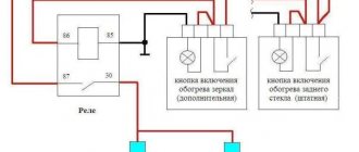
We connect the positive outputs of the turn signals (green-yellow and green-black alarm wires) and parking brake control:
We cut the handbrake wire (brown/blue) and put a diode in the gap, with the cathode towards the handbrake, from the cathode point we take a signal for the alarm (orange-violet alarm wire No. 16 from the 18-pin connector).
We connect the wire for monitoring the door limit switches (the harness is slightly higher than that indicated when connecting the turn signals and parking brake, it goes under the panel):
Isolation by diodes is necessary to eliminate potential from the lampshade during “polite lighting”. We connect the “To alarm” wire to the blue-black wire of the 18-pin alarm connector
We monitor engine operation from the injector wire (under the hood in the corrugation for the injectors - a blue wire through a 1uF 160V separating capacitor to a gray-black alarm wire).
We attach the engine temperature sensor to the pipe to the radiator
We program according to Table 2 (installation instructions) cranking the starter - 3.6 seconds (function 9, No. 4), control by tachometer (function 11, No. 4).
source
Where is the central locking block of VAZ 2115 located?
How to quickly, easily and most importantly correctly disable the immobilizer on a VAZ 2115?
All modern cars, including cars from the domestic automobile industry, are equipped with immobilizers. Immo. This is an anti-theft device that allows you to block the engine in the event of a car breakdown. But like any other electronic device, over time this device may malfunction or cause problems, in which case car owners will have to turn it off. How to disable the immobilizer on a VAZ 2115 with your own hands, we will talk about this below.
Content
general information
Firstly, it will be useful to know where immo is located, because if this device is not working, you need to get physical access to the device to disable it. In VAZ 2115 cars, immo is located behind the center console to the right of the steering wheel.
Today there are two types of contact and non-contact devices. Contact systems are operated by keys, and special circuits built into the key chain or card are used to operate contactless ones. As for VAZ cars, immo is installed only on injection versions of the car.
How does it work
The operating principle of this device is based on communication between the control unit and immo. The anti-theft device transmits data to enable or disable the starting power supply. If disabled, the system automatically blocks the ignition circuit via the fuel pump and therefore the engine will not be able to start. That is, without initializing the power supply it does not work
READ Bend Li Valve For VAZ 21099 Injector
When should I disconnect?
In what cases do you need to disable the installation of the anti-theft system:
- If you are dealing with manufacturing defects, this is a disadvantage. Especially, this applies to the earliest versions of vehicles on which such devices were installed. In later versions, VAZ engineers added an alternative engine starting function, bypassing the protection. But you must keep in mind that in this case the parameter will only work once, if a failure occurs, you need to enter the access code, then activate the function and press the gas pedal a certain number of times.
Moreover, this operation will need to be repeated 6 times. For example, if your password is 123897, you first press the pedal once, then twice (after a short period of time), then three more times, then eight times, etc. This function is described in more detail in the service brochure.
- If the battery is completely discharged, the control unit may correct this as an error that will prevent the engine from starting in the future. As mentioned above, the immobilizer control module communicates with each other through a diagnostic line. Therefore, if the circuit loses power, it is an error.
- The lock can also be connected to a control unit. For example, if a driver uses diagnostic equipment to check vehicle systems, a code failure may occur. In this case, inflammation must be turned on. Additionally, interference caused by the smartphone may also be the cause of the crash.
- Also, the need to bypass immo may be associated with banal failures in its operation (author of the video channel IZO))) LENTA).
READ How Much Oil to Fill the Shock Absorber
VAZ 2114 EPC (22). The central locking is working!
earned JS! Possibly due to warming!
VAZ 2109 Central Lock does not work. Electrical wiring repair.
VAZ
2005 2109 injector.
Problems with the alarm. The central locking
does not work . Definition of anxiety.
Disable immo instructions
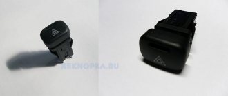
If your car is equipped with an alarm system or central locking, you do not have to worry about the safety of the car when you turn off immo. If you don't know how to turn off the alarm, this is done using the service button, commonly known as Valet. in detail in the service manual. We won't describe this as it is unique to each individual car model.
As for immobilizers, they are disabled according to the following principle:
- First you need to disconnect the control unit connector.
- Next you need to disassemble the control device . To do this, unscrew the side covers using a screwdriver in the so-called console door, then disconnect the terminals and remove the device.
- Now you need to read the EPROM. EPROM is a non-volatile memory; it is needed precisely because it contains data on the operation of the anti-theft device. When finished, the EPROM is replaced.
- The PAK loader must be disconnected from the control module.
- Disable the module to prevent the device from being automatically locked during installation.
- Then we proceed directly to disassembling the immobilizer. As mentioned above, it is located behind the center console on the steering wheel. IS a block at the audio system level.
- You need to feel and disconnect the plug with your hand; it has 20 contacts. Having done this, you can begin to restore the K-Line, for this you will need to close the contacts on the connector, in particular we are talking about outputs 9 and 18. That is, they must first be cut and then isolated. When this is done, reinstall the device and try to start the engine. If you did everything correctly, the engine will start.
READ How to Remove Matiz Ignition Switch
Connecting the central lock
First you need to study in detail the connection diagram for the central locking on a VAZ car - 2115,2114. Finding it is not a problem by searching on the Internet.
The central locking control module is located on the left under the dashboard. Looking there, you will find six wires coming out of the module housing. To install the alarm, you must disconnect the blue and brown cords. As a result, we get a connection corresponding to the following diagram:
Before connecting the alarm, you should make sure that it is not a toggle switch installed on the driver's door, but a standard actuator with five outputs. Otherwise, you will need to install an actuator, which is quite problematic.
On VAZ -2115,2114 cars, the white wire, which is connected to the seventh terminal, is usually responsible for unlocking. If there are no connections at terminals 7 and 5, then the eighth terminal is connected to the brown cord. It is this cord that is responsible for unlocking in this case.
Terminals number five and six are responsible for locking the lock. This arrangement of contacts is typical for almost all blocks of the “ninth” series.
For some reason, none of the instructions for alarms ever indicate that installation requires the purchase of additional elements.
We will definitely need:
- Two to three 1N4001 diodes per Ampere
- One 1N5401 3 Ampere diode
- Two 4 or 5 Ampere diodes if there are no separate outputs for turn signals.
When installing a Starline alarm system, the task is greatly simplified, since significantly fewer additional parts are needed.
Where is the central locking of the VAZ 2114
The central locking system is located in the driver's door, just like the electric drive. If we talk about the system as a whole, it is distributed over 4 doors (in some cases it also extends to the trunk), and the central panel (control unit).
Testing and diagnostics
If your car is equipped with one of the alarm systems, then it is better to start diagnostic activities with it. You should check the operation of the central locking when using the key fob, and when opening and locking with a key. If, during a manual check, the central locking system works correctly, then the reason is the alarm. Additionally, it would be a good idea to check the battery charge level, since if it is insufficient, interruptions in the operation of many electrical consumers occur. In general, it is best to check, as they say, along the path of least resistance. That is, diagnose something that does not require significant effort. And if the fault cannot be identified, resort to disassembling the driver's door and examining the mechanisms along with the electronics.
conclusions
In this article, we touched upon only some of the most common problems associated with the operation, repair and maintenance of a centralized lock. Despite the fact that the node has plenty of problems, restoring its functionality is not a difficult, much less an impossible task. Usually, to achieve smooth, efficient operation of the system, only practical skills are missing. After receiving them, you will be able to repair any complexity! If you want to install the central locking on a VAZ 2114 yourself, then here is a video instruction:
Connection diagram
After carefully studying the alarm installation instructions, you can find the following connection diagram:
In this diagram, the designation X2 indicates a six-pin connector. It must be connected according to the diagram above. If you need to install an additional actuator, then it is better to use the diagram given in the instructions.
Now let's figure out how to connect the door sensors. For this purpose, there is a special wire in the connector marked X3.
Tapping into wires
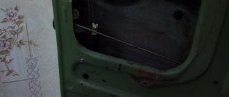
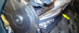
Next to the driver's door, there are two wire harnesses running right along the floor. One of them has a cable coming from the parking brake and two wires to the turn signals. The second harness contains the door switch cable. This is where you need to start connecting. To do this, remove the sill trim along with the side panel. They are attached using self-tapping screws that must be unscrewed. Having done this, you can see the wiring harness shown in the photo:
This harness goes to the dashboard. We are interested in the door switch cable. If a 1N5401 diode is inserted into the wire break, the current should flow towards the limit switches. And the second diode 1N4001 is connected as shown in the figure.
The following figure shows the second harness:
At the same time, taps are made from the blue cables and the cords are pulled to the place where the alarm will be installed. And the handbrake wire is cut, and a 1N4001 diode is soldered into the cut with the cathode towards the switch.
Connecting to wires
Connection to the “four” wires must be carried out in the order indicated above. In this case, you must follow the instructions in the instructions for the alarm. But first you need to place all the alarm elements in the car.
Useful : VAZ 2114 emergency gang diagram
Before starting work, turn off the battery power. The device control unit is placed under the dashboard. The siren must be located in the engine compartment. An emergency siren should also be installed there. In the trunk, under the hood, and also in the engine compartment, you need to install limit switches for opening. Place the Valet button in a place hidden from prying eyes. Attach the antenna of the security device to the windshield in the upper right or left corner. Place the shock sensor on a metal surface. Next, the car alarm is connected according to the diagram. To connect it to the central locking you need to purchase the following items:
- 2-3 pieces of 1N4001 diodes for a current of no more than one Ampere;
- One 1N5401 3 Ampere diode;
- Also, some security systems may require two 4-5 Ampere power diodes.
To connect the device to the central locking system, you need to find two wire harnesses on the floor next to the driver's door. To get them, you need to remove the sill trim and side panel. The first harness contains the door switch cable. A 1N5401 diode must be installed in its gap.
In the second harness you need to find the wire going to the handbrake, into which you should insert the second 1N4001 diode.
The blue cords of both harnesses must be connected to the car alarm.
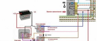
Connecting autorun
The VAZ-2114 models use an ignition switch with three terminals - 15 (blue wire), 30 (lilac) and 50 (red). Terminal 30 is connected to the battery. When you turn the key, blue wire 15 is connected to this terminal. The third terminal is responsible for the starter.
As it is written in the instructions, it is quite possible to power the alarm from contact 30, from which the lead is made. And the cable from connector X1, yellow, is connected to connector 15.
After all the actions taken, the connection of the tachometer remains. In this case, a loop antenna and a reading device are combined. Connector X3 has a gray-black outgoing wire. It is connected to the tachometer as shown in the VAZ dashboard diagram:
This will allow the alarm to control the speed. And at the very end we connect the ground from the main unit. This is a black cord from connector X3.
How the central lock works
The operation algorithm of the central locking system consists of sending a pulse to the VAZ 2114, in which the received signal is analyzed and commands are generated that control the door locks. They are either opened or locked.
General scheme of central locking
Elements that activate the central locking are connected to pin 30. If contact 87 closes, then the activator outputs will be affected by ground. When a certain relay 30 is activated, the contact will connect to the positive. Thus, the activator will receive power and the rod will begin to move. The control unit rod closes different pairs of signals depending on what action needs to be performed: closing or opening the doors.
Since the central locking activators are connected in parallel, all doors will either open or lock at the same time. Central locking can be pneumatic or electric. The first type of device includes a control panel, compressor and tubes. In an electric one, the main element is a motor, thanks to which the mechanisms are activated.
Settings
Only autorun functions can be configured. To activate programming mode:
- Disable security
- The ignition key is set to position 0.
- Then press the Valet key six times in the main block.
- Turn on the ignition
- After six beeps, use the same key to select the desired function, and use the key on the key fob to select the desired value.
The optimal settings for VAZ - 2115.2114 will be the following: function 12 - set to value 3, function 11 - value 4, function 9 - value 3. To select value 4, press and hold the third button until the melody is played.
After playing, press it again. To check the correct connections, perform the following steps:
- Disconnect the yellow cord from block A91 to terminal 15 for a while.
- The engine is started using the ignition key
At the same time, the alarm indicator should blink.
source
Installation of alarms on VAZ-2114
Next we will look at how to correctly connect the signaling system on cars of the VAZ 2114 family. The following will be implemented: connection to the central locking, auto start, reading the status of door limit switches. To control the central locking, the VAZ plant produced BUBD modules. If such a module is missing, the task will be simplified - you will not connect the central locking system. The same applies to the case when the driver's door only has a switch, but not an actuator. All tables given here are suitable for the Starline A91 Dialog alarm system, and to set up another system, use the instructions for it.
Features of central locks of VAZ models
Before connecting the alarm to the central locking on a VAZ 2114, 2110, you need to understand the features of the central locks of VAZ models. Electromechanical locks are used as an actuator in the doors of domestic cars, the control of which is provided by all popular car alarm models.
All standard central locks of VAZ models installed at the factory (VAZ 2110, 2111, 2114, Lada Granta, Kalina, Priora) are controlled by a negative impulse. To connect the alarm, you need to find the negative control wire and apply the negative wire to it from the main car alarm unit.
If you installed a central lock on a domestic model from an imported car, it can be controlled by a positive impulse. In this case, the door closes when positive voltage (12 V) is applied.
A circuit diagram will help you figure out how to connect the alarm to the central locking on a Priora and understand the pinout of the wires.
Connection diagram for the alarm system to the central locking system on the Priora
You can find similar diagrams for other VAZ models on the Internet or in technical literature.
Basic information about the car
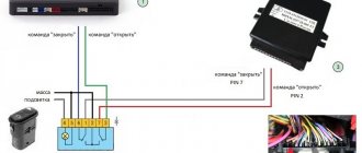
When starting to install the alarm, you need to understand exactly where and what is located in the car, and what you will connect. Let's look at the connection diagram for the VAZ central locking system:
The control module is located under the dashboard on the left, and its connector attached to the body contains six wires:
When installing an alarm, the “blue” and “brown” cords are broken to obtain the following diagram:
The wiring of the 6-pin connector mounted on the main Starline A91 module is given below. Carefully study the principle of operation of the circuit: the limit switch here is in the “closed” position.
Before connecting the alarm to the ACU, make sure that a standard 5-wire actuator is installed in the driver's door, and not a toggle switch. It’s unlikely that anyone will be able to install the actuator with their own hands by running two cords to the engine in 5 minutes. In general, it is sometimes better to refuse to connect the signaling system to the central locking system.
Let us take the liberty of revealing VAZ’s proprietary secret:
- If you see a "white" control wire connected to terminal "7", it is responsible for unlocking (as opposed to the "brown" one);
- If terminals “5” and “7” are not used, a “brown” cord will be connected to terminal “8”, and it is then responsible for unlocking.
The locking contacts are terminals 5-6. The two outer terminals are responsible for unlocking. This is true not only for model 2114, but also for BUBD units of the “ninth” family in general.
The instructions for the alarms usually do not say that you will need to buy additional parts before installation. These include:
- Diodes 1N4001 (2-3 pcs.) – designed for current up to one Ampere;
- 1N5401 (1 pc.) – three-amp diode;
- To install any car alarm that does not have separate outputs for turn signals, you need to purchase two power diodes (4-5 Amperes).
The latter, as you might guess, does not apply to the Starline A91 system. And this is great luck.
When installing any Starline system, you usually spend less than 100 rubles on parts.
Features of the VAZ central lock
Everyone knows that the Lada models listed here use central locking controlled by negative polarity. This literally means the following: we apply “0 Volt” to one wire - all locks close. We apply the same voltage to the other wire (second) - they unlock. This is done in many European cars. What does it mean to “supply “0 Volt”? This means connecting the wire to ground.
Central locking control unit connector
The central locking control unit has the following wiring:
- Black wire – ground (connected all the time);
- Pink – power supply “+12V” (built-in fuse is used);
- Yellow, red - connected to the actuators in the doors (these wires are not connected to the signaling system!);
- Brown, white - control wires, just those that have already been mentioned.
Let's look at the central locking connection diagram, which is implemented “from the factory”:
Standard connection diagram for central locking
First, we may decide that the triangular connector (labeled “C”) is suitable for our purposes, since it contains control contacts. But please note that the standard circuit uses a microswitch located in the driver's door. We will break two wires coming from this switch, and the relays built into the alarm unit will be connected to the breaks. Other options are excluded.
Connection diagram and setup
In the basic instructions, Starline provides a diagram for the A91 model:
Shown here is the harness going to the dashboard. Let's figure out what is connected where:
- The diode connected to the wire break must conduct current in the direction “towards the limit switches”;
- Above we talked about the 1N5401 diode;
- The second diode connected to the alarm wire may be designated 1N4001 (it is cheaper).
The Starline A91 Dialog alarm is equipped with a set of inputs connected to the door, trunk and hood limit switches. The one you need is the "17" cord from connector X3. In the diagram it is designated as “blue-black”.
Now let's look at what is in the second bundle, located under the first:
How to connect
Installation of the VAZ-2114 alarm system begins with disconnecting the battery and determining the location of the elements. The control unit is placed under the instrument panel or behind the glove box, the siren is placed in the engine compartment. Guided by the instructions and diagram, all elements are connected.
The control unit is connected through connectors to system elements, components and vehicle parts. Installation and installation begin from the farthest point of installation of the security system element, using 9 connectors (X) for connection.
Sensors (limit switches) are installed in the engine compartment, under the hood and in the trunk, which react to opening. The door trims are dismantled to install activators. The Valet service button is installed in a place hidden from prying eyes, but easily accessible to the car owner.
A transmit-receive antenna is installed on the windshield in the upper corner. It is recommended to install the shock sensor inside the passenger compartment, securing it to a metal surface. The emergency siren is installed in the engine compartment with the bell facing down.
When all the elements are located in their places, you can begin to connect them into a single system.
Scheme
The characteristics of the Starline A 91 car alarm and the connection diagram of the main elements are given in the manufacturer's instructions. When connecting a 6-pin connector X 2, you may need an additional door opener activator.
When connecting door opening sensors, use the blue/red wire of connector X 3. All alarm connection points, i.e. connectors (X) look like this:
- X 9 - connect a two-level shock sensor installed on a metal surface.
- X 8 and X 7 - connectors are not used.
- X 6 - Valet service button, installed in a hidden and easily accessible place.
- X 5 - LED indicator, installed on the instrument panel.
- X 4 - transmitting sensor receiving module; it is recommended to install it in one of the upper corners of the windshield.
- X 3 - connector with many wires.
They are connected to the systems with wires of the following colors:
- Red - with the “plus” of the ignition switch.
- Green/yellow and green/black - sidelights and side turns.
- Black—vehicle mass.
- Yellow - ignition switch (connection to blue/black).
- Gray is the “plus” of the emergency siren.
- Blue/red - “plus” of the door entrance.
- Black/red - additional blocking relay.
- Orange/gray - hood lift sensor.
- Orange/white - trunk opening sensor.
- Orange/purple - to the brakes (according to the diagram in the instructions).
- X 2 - connect door opening activators;
- X 1 - ignition switch (closed with red wire).
Connecting the central lock
In basic configurations, the control unit (CU) of the central locking (CL) performs the function of locking the door lock. The electrical circuit connection diagram is the same for all central locks, the only difference may be in the control unit, activators and the number of pins for connecting an additional device.
The main elements of the central lock include the control unit, door sensor switches (limit switches) and microswitches that fix the position of the key. All these elements are connected to the alarm and interior lighting of the car.
To connect to the central locking, it is necessary to connect the central locking control unit (CU) to the car alarm using the door opening and closing relay, to the car ignition switch and to the door opening sensors. When installing the central locking, you will need additional parts, such as:
- diode 1A - 3 pcs.;
- 3A diode - 1 pc.;
- diode 5A - 2 pcs.
Tapping into wires
In order to insert into the wires, you first need to free them from under the threshold trim. To do this, unscrew the fastening screws and remove the upholstery. Underneath there are 2 wire harnesses running to the instrument panel. One of the harnesses contains the parking brake wire. 2 wires are connected to the sidelights and side indicators.
When inserting into the parking brake wire, 1 diode is installed, and 2 diodes are installed in the wire that powers the side headlights and side turn indicators. The terminals of the insertion wires are connected to connector X 3 of the alarm control unit.
Autostart
One of the functions of the Starlin car alarm system is auto engine start. In order to install with autostart yourself, you need to use the ignition switch wires. The lilac wire is connected to the battery. Blue (ignition switch) is connected to the alarm control unit via connector X 1.
To connect the tachometer sensor, it is connected to a gray/black wire coming from connector X 3. Connect ground from the main unit using the black wire of connector X 3.
Central lock designs
Advanced car central locking configurations include:
- Control block;
- electrical supply cables;
- input sensors;
- remote controls;
- actuators (actuators);
- additional devices (window closers, electric sunroof, electric trunk locks, fuel hatch lock).
In basic configurations, the central locking control unit, after turning the key, removes the locks from the locks of all doors, activating the actuators.
The same functions are performed by the car alarm control unit, which is devoid of actuators, so harmonizing two systems built on different principles becomes the main task of the installer.
The basic diagram of connecting electrical circuits is the same for all types of central locks, car alarms, only the design of the control unit, actuators, and the number of pins for connecting additional devices change.
General diagram of connecting the alarm to the central locking
Important elements of the central lock, in addition to the control unit, are door limit switches (“limit switches”) and microswitches that fix the position of the key and locking mechanisms. These elements must be connected to interior lighting and car alarms.
Differences in designs of actuator drives (electric, pneumatic), types of control (negative, positive pulse, variable polarity) are important for understanding the theory. In practical work, the car enthusiast focuses on a specific model of central locking.
Checking the correct connection
Having installed all the elements of the alarm system, they configure the functions after activating the registration mode. To do this, you need to turn off the ignition, press the Valet button six times, and turn on the ignition. The sound of the signal six times will confirm the system’s transition to registration mode.
The selection of functions is made by pressing the buttons on the alarm key fob. The correct connection is checked by performing the following operations:
- Disconnect the wire (yellow) going from the A91 alarm control unit to the ignition switch to the terminal with the blue wire.
- The ignition key is used to start the engine
- The intermittent light of the alarm indicator confirms that the system elements are connected correctly.
In order to increase the level of protection of your car, you won’t need a lot of material costs. But only on the condition that the installation of the alarm system is done independently, with your own hands.
source
Practical connection operations
To install a car anti-theft alarm you will need simple tools and materials:
- screwdrivers, wrenches (special pullers are not needed to dismantle interior elements of VAZ models);
- soldering iron and soldering accessories (solder, acid);
- multi-colored single-core cables (selected according to the colors of the standard electrical wiring or the pinout of a specific electrical circuit);
- linear meters and multimeter;
- insulating materials;
- fastening elements (special plastic clips are preferred).
The easiest way to find the central locking control unit is when installing the main car alarm control unit. For example, on the VAZ 2110 it is located rather inconveniently.
Most often, for the convenience of installing alarm elements, you have to completely disassemble the dashboard, door cards, remove the trunk upholstery, and disassemble electrical devices of lighting systems.
During installation, it is convenient to use wires of the same colors as those coming from the central locking control unit.
Having disassembled the door card, you can connect the control wires directly to the electric drive of the lock.
It depends on the car alarm model whether you need to purchase additional relays. Sometimes standard fuses and power switches may not withstand the additional load.
The easiest way to connect a car alarm to the central locks of VAZ models is to solder into the wire breaks (usually white and brown). To do this, you need to lay a four-wire cable from the two internal relays of the alarm unit to the eight-pin connector for controlling the door microswitches.
To avoid oxidation and damage to the integrity of the wires (this leads to false alarms), you must follow simple rules:
- carry out electrical installation work with the battery disconnected;
- connect electrical wiring only by soldering or terminals, insulate connections;
- use cables with a small margin in length, lay them in bundles, and securely fasten them to body elements;
- Observe the color of the cables for easy identification during alterations or repairs.
After completing the electrical installation work, do not rush to reinstall the removed parts. The final assembly of interior elements, doors, trim is carried out only after installing all elements of the anti-theft alarm system, making adjustments, and checking the functionality of the security system.
You can see in detail how to connect the alarm system to the central locking on a VAZ 2110 in the video: