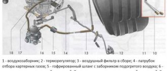
The Solex carburetor is one of the main components in the fuel supply system, on which the efficiency of the entire vehicle depends. These carburetors are very popular today.
The main reasons for their popularity are fuel efficiency and high efficiency of your power unit. However, to achieve such indicators it is necessary to configure it.
Setting the float chamber level
First of all, you need to pay attention to the fuel level in the float chamber.
Even on a new carburetor, this procedure must be carried out, since each car has a different fuel pump, the number of gaskets under them can also vary, which can lead to different pressure levels on the carburetor shut-off valve or needle, and this in turn leads to an overly rich mixture ( overflow).
The adjustment procedure is as follows:
- It is necessary to start the engine and carefully apply gas to check the efficiency of the carburetor;
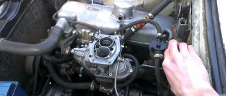
- Remove the air filter from the carburetor and the fuel hose.
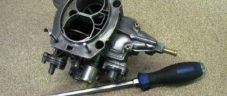
- Unscrew the 5 bolts and remove the carburetor cover. Be sure to vertically so as not to damage its floats. Place this cover on a flat surface.
- When removing the carburetor cap, the fuel level should be at the red lines. The fuel depth must be measured. This figure should be about 29 mm. The procedure should be carried out immediately after removing the carburetor cap, since gasoline tends to evaporate.
- The height of the floats needs to be adjusted. We measure the distance from the cardboard gasket of the carburetor cover to the top of each float.
- The recommended figure is 34 mm. If necessary, you need to bend the levers and float tongue.
- Let's start adjusting the full stroke of the floats. The permissible lift of the lower angle of the float is 15 mm, and the full stroke of the float is 25 mm. Make sure that the edges of the floats are parallel to the sealing surface of the cover.
Idle speed setting
After setting the level in the float chamber, we assemble the carburetor and warm up the car engine to operating temperature. In this video, they will tell you and show you how to set the idle speed in a Solex carburetor, as well as the main reasons for its absence.
Next, we turn it off and carry out the following operations:
- Using a flat-head screwdriver, tighten the mixture quality screw until it stops (position 7).
- We turn it back from this position 4 - 5 turns.
- We start the engine, do not forget to completely remove the choke, and using the mixture quantity screw (position 6) set the minimum engine speed to about 800 per minute so that the engine runs stably.
- We tighten the mixture quality screw until the engine starts to run unstably. Then we turn it back 0.5 - 1 turn, which should bring the engine to a relatively stable position.
- Using the mixture screw, set the engine speed to about 800 - 900 per minute. If the engine starts to stall, unscrew the mixture quality screw a little more.
When setting the idle speed, some problems may arise:
The engine does not slow down when the mixture screw is tightened (a lot of fuel gets into the idle channel and this screw cannot shut it off).
Causes:
- large jets installed;
- the solenoid valve is not tightly screwed in, and fuel is sucked past the nozzle;
- deformation of the nozzle seat or itself.
So, for example, if the engine stalls when removing the wire from the solenoid valve, this means that the jet is installed too large.
Checking the Solex carburetor adjustment
After completing all the settings above, you should check the accelerator pump.
With the engine off and the air cleaner removed, manually sharply press the throttle valve open. Streams of gasoline should appear. They should appear immediately, without delay. Otherwise, when accelerating, the car will seem to fall into a short-term hole, and then shoot out.
You also need to check the economizer, or rather, its diaphragm for integrity. This is done by unscrewing the economizer cap.
A malfunction of the economizer diaphragm can be determined by the following signs:
- when the ignition is turned off, the engine runs for some time;
- noticeable unstable engine operation;
- increased fuel consumption;
- the engine does not stall when the mixture quality screw is tightened.
After checking, it is advisable to thoroughly clean the carburetor and blow it with compressed air. In general, it is better to clean the Solex carburetor and blow out the jets with compressed air. This is both effective and safe for jets.
It’s not at all difficult to adjust the Solex, try it and enjoy!
Selection of jets
Some parameters of serial carburetors are far from the standard ones, since the dimensions of some parts have manufacturing deviations. An interesting and very useful video from which you will learn how to modify the Solex 21083 carburetor.
Thus, the spread in the parameters of some serial carburetor parts can reach up to 5%. Therefore, when adjusting the carburetor, make sure that the jets are in good working order. The selection of jets is carried out taking into account the working volume of the car.
If the engine has a large displacement, then it is necessary to install small jets, since an increase in volume requires more air passing through the diffuser, which affects gasoline consumption. Their adjustment should begin with the fuel jet, and then, if necessary, move on to the air jet.
You need to have several jets available with higher and lower productivity than the installed one.
Our actions:
- Using a wire, secure the throttle valve of the second chamber to eliminate its influence.
- Next, we select the jets, for example, the jet marked “107.5”, which is our basic one, change to “105”, and then “97.5”. We reduce the throughput of the jets until dips appear when the throttle is open or twitching when driving. When these signs appear, you should unscrew this jet and replace it with the previous one, which had a slightly higher performance.
- If dips occur when starting the car, you should enrich the mixture slightly by adjusting the idle system.
If you are trying to increase the efficiency of your car, then it is not recommended to reduce the flow area of the main fuel nozzle of the second chamber, since the acceleration process will be much longer, and all savings will be reduced to zero.
Jet markings
For each carburetor system, jets of different cross-sections are provided, so during repairs it is important to know what cross-section the fuel or air jet is needed. When purchasing a car, it comes with a service book, which outlines the main characteristics and its structure, as well as a jet marking scheme depending on the carburetor model.
The main metering system has fuel jets marked 80 or 95 for the primary chamber and 100 for the secondary. There are also air jets 150, 155, 165 for the primary chamber and jet 125 for the secondary. The idle system includes fuel nozzles marked 38-44 and 50, and air nozzles 170 and 160. In the secondary chamber of the transition system, fuel nozzles 50 and 80, and air nozzles 120 and 150. For the main metering system, a fuel nozzle 85 is provided.
Adjusting the accelerator pump
Accelerator pump metering systems
The main task of the accelerator pump is to supply a smooth and powerful stream of gasoline through the open carburetor throttle valve (dripping and sluggish stream are not allowed). The stream of gasoline should enter directly into the manifold, without touching the walls of the diffuser and throttle valve.
Flowing of gasoline down the diffuser stack or throttle valve is not allowed, since the car will become very blunt and jerky when you press the gas sharply.
An accelerator pump with two spouts must be installed in different chambers. You can insert two spouts into the primary chamber - this can increase the agility of the car, but also lead to excessive “overflow”.
Setting the transient mode of carburetor operation
At idle speed, the carburetor throttle valves close and a high vacuum area is created under them, which allows gasoline to be “sucked” out of the idle channel through the nozzle. If the damper is opened sharply, the vacuum decreases sharply, which disrupts the normal operation of the main dosing system of the first chamber and a failure appears.
To eliminate these symptoms, adjust the idle jet or accelerator pump nozzles. The adjustment must be made on a warm car engine.
The idle jets or accelerator pump are changed one by one to prevent dips and delays when you press the gas sharply.
You may need to adjust the idle speed a little. Over-enrichment is not transiently displayed as black smoke coming from the exhaust pipe.
Do-it-yourself interior tuning. How to do this and what is needed for this can be found on our unique website.
From here, you can learn how to do tuning a Chevrolet Niva with your own hands.
In this informative article, you will learn how to polish a windshield with your own hands.
It is recommended to install an accelerator pump with 40x40 nozzles, and an idle nozzle with parameters from 35 to 40. If there are dips from a lean mixture and it is not possible to adjust the idle speed due to the idle nozzle being too large, then both accelerator pump nozzles can be placed in the first camera as shown in the picture.
Carburetor SOLEX 21083 diagram and device
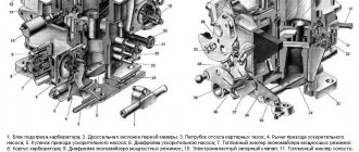
Diagram of carburetors 2108, 21081, 21083 Solex installed on the engine of front-wheel drive VAZ 2108, 21081, 21083, 2109, 21091, 21093, 21099. All these carburetors are based on the same design. The only difference is in the parameters (jet sizes, etc.). Modifications of Solex carburetors installed on Niva, Oka and some rear-wheel drive VAZ car models have some features in the device (for example, the absence of a “return”, a different UN atomizer, etc.).
1
.
Carburetor heating unit 2
.
Throttle valve of the first chamber 3
.
Pipe for suction of crankcase gases 4
.
Accelerator pump drive lever 5
.
Accelerator pump drive cam 6
.
Accelerator pump diaphragm 7
.
Fuel jet for power mode economizer 8
.
Pump housing 9
.
Power mode economizer diaphragm 10
.
Shut-off solenoid valve 11
.
Idle fuel jet 12
.
Carburetor cover 13
.
Main air jet of the first chamber 14
.
Air damper 15
.
Accelerator pump nozzles with fuel supply valve 16
.
Trigger diaphragm 17
.
Starter adjusting screw 18
.
Idle mixture quantity adjusting screw 19
.
Second chamber locking lever 20
.
Pipe for supplying vacuum to the vacuum regulator of the ignition distributor 21
.
Idle mixture quality adjusting screw 22
.
Throttle valve control sector 23
.
Throttle valve drive lever 24
.
Adjusting screw when opening the throttle valve of the first chamber 25
.
Air damper control lever 26
.
Starter rod 27
.
Electrical wire of the limit switch of the forced idle economizer 28
.
Choke lever 29
.
Main air jet of the second chamber 30
.
Emulsion tube 31
.
Sprayer of the main dosing system of the second chamber 32
.
Fuel supply pipe 33
.
Fuel drain pipe into tank 34
.
Fuel filter 35
.
Needle valve 36
.
Throttle valve of the second chamber 37
.
Throttle lever of the second chamber 38
.
Main fuel jet of the second chamber 39
.
Throttle valve drive lever of the second chamber 40
. Float.
|.
The first chamber of the carburetor. ||. Second chamber of the carburetor. 1
.
Accelerator pump drive lever. 2
.
Trigger diaphragm adjustment screw. 3
.
Trigger diaphragm. 4
.
Air duct of the starting device. 5
.
Solenoid shut-off valve. 6
.
Fuel jet for idle system. 7
.
Main air jet of the first chamber. 8
.
Air jet of the idle system. 9
.
Air damper. 10
.
Sprayer of the main dosing system of the first chamber. eleven
.
Accelerator pump spray pipes. 12
.
Sprayer of the main dosing system of the second chamber. 13
.
Econostat sprayer. 14
.
Main air jet of the second chamber. 15
.
Air jet of the second chamber transition system. 16
.
Balancing channel of the float chamber. 17
.
Float chamber. 18
.
Fuel needle valve. 19
.
Fuel return fitting. 20
.
Mesh filter. 21
.
Fuel supply fitting. 22
.
Power mode economizer diaphragm. 23
.
Fuel jet for power mode economizer. 24
.
Ball valve for power mode economizer. 25
.
Float. 26
.
Econostat fuel jet with tube. 27
.
Fuel nozzle of the second chamber transition system. 28
.
Emulsion tube of the second chamber. 29
.
Main fuel jet of the second chamber. thirty
.
The outlet of the transition system of the second chamber. 31, 33
.
Throttle valves. 32
.
Damping jet. 34
.
Slot of the transition system of the first chamber. 35
.
Idle air system outlet. 36
.
Heating block. 37
.
Adjusting screw for the “quality” of the fuel mixture. 38
.
Crankcase ventilation system fitting. 39
.
Vacuum tap connection to the vacuum ignition timing regulator. 40
.
Main fuel jet of the first chamber. 41
.
Emulsion tube of the first chamber. 42
.
Accelerator pump ball valve. 43
.
Accelerator pump diaphragm. 44
. Accelerator pump pusher.
How does Solex differ from Ozone and Weber?
The main difference between Solex carburetors and devices of previous families is the possibility of installing it on transversely located power units with the float chamber forward. This installation option made it possible to eliminate the leanness of the fuel mixture when the car enters a turn, climbs, or during sudden acceleration. In addition, Solex has a completely different float chamber design. It has a two-section design, which allows the device to be used both on front-wheel drive cars and on classic cars.
Modifications and applicability of Solex carburetors
| Modification | Applicability | Engine volume, cm3 | Notes |
| DAAZ-2108–1107010 | VAZ 2108, 2109 | 1,3 | |
| DAAZ-21081–1107010 | VAZ 21081, 21091, ZAZ 1102 | 1,1 | |
| DAAZ-21083–1107010 | VAZ 21083, 21093, 21099 | 1,5 | |
| DAAZ-21083–1107010–31 | VAZ 2108, 2109, 2110, 2111 | 1,5 | Has a semi-automatic starting device |
| DAAZ-21083–1107010–35 | VAZ 2108, 2109, 2110, 2111 | 1,5 | Has a two-level semi-automatic starting device (winter/summer) |
| DAAZ-21083–1107010–62 | VAZ 2109, 2115 | 1,5 | Has an electronic device for controlling the composition of the combustible mixture |
| DAAZ-21083–1107010–05 | VAZ 2109 | 1,5 | |
| DAAZ-21412–1107010, DAAZ-21412–1107010–30 | AZLK 2141, 2141–23 | 1,5/1,8 | |
| DAAZ-1111–1107010 | VAZ 1111, 11113 "Oka" | 0,65/0,75 | |
| DAAZ-21051–1107010 | VAZ 2103, 2105 | 1,5 | |
| DAAZ-21053–1107010 | VAZ 21074, 21061 | 1,6 | |
| DAAZ-21051–1107010–30 | VAZ 2104, 2105 | 1,3 | |
| DAAZ-21053–1107010–62 | VAZ 2107, 21072, 21074 | 1,3/1,5/1,6 | |
| DAAZ-21073–1107010 | VAZ 2121, 21213 "Niva" | 1,6/1,7 |
What is the difference between carburetor 21081 and 21083
If you compare the two main modifications of Solex carburetors (21081 and 21083), used on front-wheel drive Sputniks and Samaras, then visually you will not find any differences between them. The difference exists only in the operating parameters of some of their elements.
Table: comparison of basic calibration data for Solex 21081 and 21083 carburetors
| 21081 | 21083 | |||
| For 1st camera | For 2nd camera | For 1st camera | For 2nd camera | |
| Mixing chamber diameter, mm | 32 | 32 | ||
| Diffuser diameter, mm | 21 | 23 | 21 | 23 |
| Air jet of the main dosing system | 165 | 135 | 155 | 125 |
| Fuel jet of the main metering system | 95 | 97,5 | 95 | 97,5 |
| Idle air jet | 170 | 170 | ||
| Idle fuel jet | 39–44 | 39–44 | ||
| Air jet of the second chamber transition system | 120 | 120 | ||
| Fuel nozzle of the second chamber transition system | 50 | 50 | ||
| Economizer fuel jet | 40 | 40 | ||
| Accelerator pump cam number (size) | 4 | 7 | ||
| Throttle valve starting gap, mm | 1,0 | 1,1 | ||
| Air damper starting gap, mm | 2,7±0,2 | 2,5±0,2 | ||
| Needle valve hole diameter, mm | 1,8 | 1,8 | ||
| Vacuum regulator hole diameter, mm | 1,2 | 1,2 | ||
Carburetor VAZ 2109 Solex - Setup video
© 2016-2021 24techno-guide.ru
All rights reserved.
Use of site materials is possible only if you install an active direct link to our resource. FEEDBACK
Home
(Main page of the site)
Auto
(Reviews, reviews, test drives of cars)
Engines
(Description and design of various engines)
Techno
(Articles about equipment and mechanics)
Tuning
(Review of tuned cars)
Repair
(Do-it-yourself repairs)
Tractors
(Tractor special equipment)
Osago
(All about car insurance)
Car audio
(Music for the car)
Car LAWS
(Traffic rules, fines and car laws)
Lifehacks
(Tricks of life)
Photo/Video
(No comments)
All articles
(All publications that are on the site)
Setting up a second camera
As a rule, the second chamber of the carburetor is not adjustable, since all the shortcomings of the factory jets are compensated for by the econostat. The fact is that at high speeds, when a vacuum occurs in the carburetor, additional gasoline is supplied through the econostat, which makes it possible to enrich the mixture.
Only the accelerator pump nozzle can be adjusted if its jet does not fall between the diffuser wall and the throttle valve.
All of the above techniques for tuning the carburetor are basic in its regulation, however, some craftsmen can additionally drill channels and throttle valves, and solder epulsion tubes.
Based on many years of experience of our drivers, Solex carburetors are a reliable design that perfectly performs the tasks assigned to it, even without any modifications.