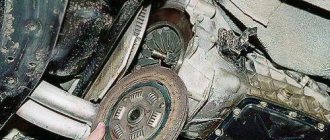
Internal combustion engines that are installed in modern cars are quite complex mechanisms with many parts. Therefore, they require proper maintenance to function properly over a long period of time.
Unfortunately, many motorists do not pay due attention to this. For example, they do not very well understand why valve adjustment is needed and often ignore this procedure, which leads to additional breakdowns and high repair costs. In this material we will talk about what valve adjustment is, which engines need it and how it is performed.
Is valve adjustment necessary?
Internal combustion engines use intake and exhaust valves. The intake valve is responsible for supplying the fuel-air mixture to the cylinder, and the exhaust valve is responsible for removing exhaust gases.
For proper operation of the VAZ 2107 engine, there must be a gap of 0.15 mm between the rocker and the valve stem. If this distance is greater, a characteristic “knock of valves” will appear. If the distance is less or there is none at all, the valve will not close completely, which can lead to “burnout of the plates.”
In addition, an incorrectly set thermal gap leads to a decrease in engine efficiency.
Purpose and design of the valve mechanism of the VAZ 2101
The operation of an internal combustion engine is impossible without a gas distribution mechanism (GDM), which ensures timely filling of the cylinders with the fuel-air mixture and removes its combustion products. To do this, each cylinder has two valves, the first of which is intended for the intake of the mixture, and the second for the release of exhaust gases. The valves are controlled by camshaft cams.
In each operating cycle, the camshaft cams alternately open the valves
The camshaft is driven by the crankshaft via a chain or belt drive. Thus, the piston system ensures time-distributed intake and exhaust of gases in compliance with the sequence of valve timing. The rounded tips of the camshaft cams press on the rocker arms (levers, rockers), which, in turn, actuate the valve mechanism. Each valve is controlled by its own cam, opening and closing it in strict accordance with the valve timing. The valves are closed using springs.
The valve consists of a rod (rod, neck) and a cap with a flat surface (plate, head) covering the combustion chamber. The rod moves along a sleeve that guides its movement. The entire timing belt is lubricated with engine oil. To prevent lubricant from entering the combustion chambers, oil seals are provided.
Springs, valve stem seals and valves have to be changed periodically
Each valve timing must strictly correspond to the position of the pistons in the cylinders. Therefore, the crankshaft and camshaft are rigidly connected through the drive, with the first shaft rotating exactly twice as fast as the second. The full operating cycle of the engine consists of four phases (cycles):
- Inlet. Moving down in the cylinder, the piston creates a vacuum above itself. At the same time, the intake valve opens and the fuel-air mixture (FA) enters the combustion chamber under low pressure. When the piston reaches bottom dead center (BDC), the intake valve begins to close. During this stroke, the crankshaft rotates 180°.
- Compression. Having reached BDC, the piston changes direction of movement. As it rises, it compresses the fuel assembly and creates high pressure in the cylinder (8.5–11 atm in gasoline engines and 15–16 atm in diesel engines). In this case, the inlet and outlet valves are closed. As a result, the piston reaches top dead center (TDC). In two strokes, the crankshaft made one revolution, that is, it rotated 360°.
- Working progress. A spark ignites the fuel assembly, and under the pressure of the resulting gas, the piston is directed to BDC. During this phase the valves are also closed. Since the beginning of the working cycle, the crankshaft has rotated 540°.
- Release. Having passed BDC, the piston begins to move upward, compressing the gaseous combustion products of the fuel assembly. At the same time, the exhaust valve opens, and under the pressure of the piston, gases are removed from the combustion chamber. In four strokes, the crankshaft made two revolutions (rotated 720°).
The gear ratio between the crankshaft and camshaft is 2:1. Therefore, during the operating cycle the camshaft makes one full revolution.
The timing belts of modern engines differ in the following parameters:
- upper or lower location of the camshaft;
- number of camshafts - one (SOHC) or two (DOHC) shafts;
- number of valves in one cylinder (from 2 to 5);
- type of drive from the crankshaft to the camshaft (toothed belt, chain or gear).
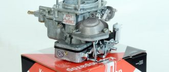
The first carburetor engine of VAZ models produced from 1970 to 1980 has four cylinders with a total volume of 1.2 liters and a power of 60 hp. With. and is a classic in-line four-stroke power unit. Its valve train consists of eight valves (two for each cylinder). Unpretentiousness and reliability in operation allows it to use AI-76 gasoline.
Video: operation of the gas distribution mechanism
Gas distribution mechanism VAZ 2101
The gas distribution mechanism of the VAZ 2101 is driven by the crankshaft, and the camshaft is responsible for the operation of the valves.
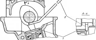
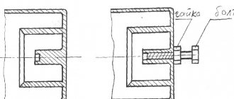
Gas distribution mechanism VAZ 2101: 1 - crankshaft; 2 — crankshaft sprocket; 3 - drive chain; 4 — tensioner bushing; 5 — tensioner adjustment unit; 6 — camshaft sprocket; 7 - camshaft; 8 — valve rocker (lever); 9 - valve; 10 — bushing for the adjusting bolt; 11 — adjusting bolt; 12 — chain damper; 13 - sprocket that controls the operation of the breaker - ignition distributor and oil pump
The torque from the engine crankshaft (1) through the drive sprocket (2), chain (3) and driven sprocket (6) is transmitted to the camshaft (7), located in the cylinder head (cylinder head). The camshaft lobes periodically act on the drive arms or rockers (8), driving the valves (9). Thermal clearances of the valves are set by adjusting bolts (11) located in the bushings (10). Reliable operation of the chain drive is ensured by the bushing (4) and the adjusting unit (5), the tensioner, and the damper (12).
The power strokes in the cylinders of the VAZ 2101 engine have a certain sequence.
The working strokes in the VAZ 2101 cylinders have a certain sequence: numbers indicate the stroke numbers, arrows indicate the direction of movement of the pistons in the cylinders
Probe for adjusting valves VAZ 2107
The distance between the rocker and the rod on a cold engine should be exactly 0.15 mm. To check and adjust, you can use either a set of universal probes or a more convenient special probe.
It is worth especially noting once again that the gap of 0.15 mm is set on a cold engine. If work is carried out “hot”, then it is necessary to take into account the coefficient of thermal expansion and set gaps of 0.20 mm.
We will also need two open-end wrenches - 13 - for the head of the adjusting bolt - 17 - for the locknut
What are valve clearances for?
In order for the engine to work at its best and develop all its performance characteristics to the maximum, the valves must move clearly and synchronously. The valves should fit tightly into their seats and open to the maximum.
With correctly set valve clearances, a hot engine works almost the same as a cold one, that is, the loss of power is minimal.
When the car is used a lot, for example, working in a taxi around the clock, the valves quickly lose their settings. Many people have probably heard, they say that the valves are knocking. This is just the time to adjust the valves.
Advice from auto experts: It is necessary to check and adjust the valves every 25 thousand kilometers of actual mileage. Of course, there are many modifications and brands of engines. It would be better to read the operating manual for the specific engine. Maybe there's no need to adjust at all.
Valve adjustment marks 2107
Before starting the adjustment, it is necessary to set the TDC (top dead center) of the gas distribution mechanism (GRM). To do this, you need to turn the crankshaft and align the point (hollow) on the sprocket with the protrusion on the body. In this position, you can begin adjusting valves 6 and 8.
You can rotate the crankshaft in the following way. Put the gearbox at 5 speed. Using a jack, lift one of the front wheels and turn it until the marks are in the position corresponding to TDC. In the same way, you can rotate the crankshaft to adjust subsequent pairs of valves.
The procedure for adjusting the valves of the VAZ 2107
So, our crankshaft is set to the TDC position according to the marks (see above). Now insert the feeler gauge between the camshaft lobe and the valve arm (rocker). It is very important that the probe fits into the gap “with interference.” If the dipstick dangles or does not fit in, it is necessary to make an adjustment.
1) Loosen the lock nut (17). 2) Turn the adjusting bolt (key 13). 3) Tighten the counter nut. 4) Check the gap again with a feeler gauge (it should fit “with interference”) 5) If the gap is too large or too narrow, loosen the lock nut again, turn the adjusting bolt and tighten it.
We repeat the above steps until we achieve the correct gap of 0.15 mm.
Do-it-yourself valve adjustment on the “Classic”
To adjust the valves on a rear-wheel drive VAZ car with a carburetor engine, prepare the tool and open the hood. The work should be done on a cold engine, the size of the feeler gauge for adjustment is 0.15 mm. We perform the following sequential actions:
- put the gearbox in neutral;
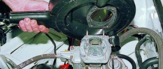
- unscrew the 3 nuts of the upper air filter cover (10th key);
- dismantle the cover and filter element;
- unscrew the 4 nuts securing the air filter housing (key 8), remove the crankcase gas hose, and move the housing to the side;
- disconnect the choke cable from the carburetor and the accelerator rod from the valve cover;
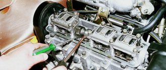
- unscrew the six bolts securing the cover;
- Having gained access to the valves, we proceed to adjustment. We take a 38mm wrench (special for a ratchet), place it on the crankshaft pulley nut, turn the crankshaft until the marks on the crankshaft align;
- We insert a feeler gauge between the r/v cam and the rocker (rocker arm), and measure the gap. The probe should enter with a slight force (tension), if it does not go through, or the gap is very large, it is necessary to make an adjustment;
- in this position of the marks, valves No. 8 and No. 6 are adjusted, the counting is carried out from the engine radiator;
- the excess clearance is determined by hand moving up/down with the feeler gauge installed; if the TK is higher than normal, the rocker will “play.” If the gap is less than the specified one, you will not be able to insert the feeler gauge;
- to adjust with a 17 key, loosen the lower lock nut, and by changing the position of the nut under the 13 key, set the required gap;
- Having adjusted the valve with the dipstick installed, holding it with the 13th key, tighten the locknut. There is one small nuance here: usually when the locking nut is tightened, the gap decreases somewhat (“tightens”), so when adjusting, the feeler gauge between the rocker and the camshaft should move a little more freely. However, you can easily adapt to this; everything becomes clear as you work;
- turn the crankshaft 180 degrees, the camshaft mark should move 90º, in this position we make the cam number 7 and 4;
- We turn the crankshaft again, here the upper mark will no longer be visible, so we are guided by the lower mark, which is located on the c/shaft pulley;
- in this position we adjust valves 1 and 3;
- Let's turn the crankshaft 180º again (the mark on the camshaft will be shifted 90 degrees from the top position, but in the other direction), adjust the clearances. No. 5 and No. 2.
Having completed the ROK, close the valve cover, start the engine, and check the operation of the engine.
Adjusting valves on a VAZ 2107 by micrometer
Instead of a feeler gauge, a micrometer mounted on a special rail is used to adjust the valve clearance. With its help you can control the amount of free play of the rockers. A gap of 0.15 millimeters corresponds to a rocker free play of 0.52 millimeters.
The rack has special nuts that allow it to be screwed onto the camshaft mounting studs. This allows it to be installed sequentially over each pair of valves. It is necessary to tighten the rack fastening nuts well so that it does not swing during measurements. After this, you need to fix the micrometer (indicator) on the rail so that it rests against the edge of the rocker that presses the adjustable valve.
To check the clearance, you need to lift the rocker cam with a special grip or finger and check the amount of free play using the arrow of the device. If it is not equal to 0.52 mm, then it should be set in the same way as when adjusting using a feeler gauge.
This adjustment method is more accurate and reliable. The feeler gauge, passing between the rocker and the camshaft, ignores the possible gap that appears as a result of wear on the parts.
Features of adjustment 2107 injector
- Firstly, there is no slider on the injection model, so the rotation angle can only be set along the camshaft (the same as for the carburetor model)
- Secondly, there is no need to remove the air filter housing to gain access to the cylinder head cover (unlike the carburetor model)
- Thirdly, to turn the crankshaft on an injection model, you won’t be able to use a 38mm wrench. You can jack up the rear wheel, put the gearbox in high gear and change the crankshaft angle by turning the rear wheel.
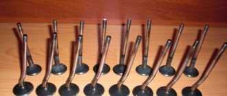
All valve train parts
1 - valve; 2 - retaining ring; 3 - guide sleeve; 4 — oil deflector cap; 5 — support washer of the outer spring; 6 — support washer of the internal spring; 7 — internal spring; 8 — outer spring; 9 — spring plate; 10 - crackers; 11 — valve drive lever; 12 — lever spring; 13 — adjusting bolt; 14 — lock nut of the adjusting bolt; 15 — bushing of the adjusting bolt; 16 — locking plate of the lever spring.
When is it necessary to adjust valves?
The normal gaps between the cams and levers provided for by the design of the VAZ-2106 engine are 0.15 mm, and reducing or increasing them will entail a number of consequences. Although their non-compliance with the established requirements does not pose an emergency hazard to the entire engine, it causes rapid wear of parts, engine overheating, a decrease in its power, and increased fuel consumption.
Typically, valve thermal clearances are adjusted every 20-30,000 km, as well as after any repair work related to the gas distribution mechanism. In addition, such a need may arise due to malfunction of other engine systems or mechanisms.
The main sign that it is time to adjust the valves is a characteristic knocking sound coming from under the valve cover. It can also be clearly heard from inside the car when the hood is closed. It is important here not to confuse this sound with the clatter of piston pins, which can occur during detonation. Valves, unlike fingers, “knock” both at idle and under load. The latter, in the event of detonation, reveal themselves only under load.
Preparation stage
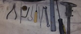
Adjusting the valves of the VAZ-2106 is not particularly difficult and does not require the use of special tools. Here you will need:
- a set of wrenches (heads) for 10, 13 and 17;
- key (head) 36 for cranking the crankshaft;
- Screwdriver Set;
- a measuring probe with a thickness of 0.15 mm (included in the tool kit for the car from the factory, can be purchased at any auto store or a special strip with an indicator);
- new valve cover gasket;
- automotive sealant;
- assistant (for greater convenience when setting valve timing).
The car must be placed in a viewing hole, secured with the parking brake, and the engine must be allowed to cool completely. After this, open the hood and remove the air filter: it will interfere with the removal of the valve cover.
How to measure valve clearance
We always check the gaps “cold”, that is, when the engine has completely cooled down.
Preparing tools:
- dipstick;
- a set of keys;
- hammer;
- puller
If the valve tappet is screw-adjustable, then turn the crankshaft until the cam is directed in the opposite direction from the tappet. Then, quietly hit the pusher with a hammer and swing it to the sides with your hand. We insert the dipstick and measure the gap between the pusher and the valve and see how much it differs from the value that should be for this engine. The dipstick has numbers stamped on it indicating its thickness.
If the valve pusher is adjustable with washers, then rotate the engine crankshaft so that the cam of this valve is directed upward. After this, we take a dipstick with the required thickness that should be in this motor.
If the required feeler gauge does not fit under the valve, then the gap is less than required. If the dipstick slides in easily and dangles there, then the gap is greater than required.
Adjustment using a feeler gauge
1.Using a 10mm wrench (socket), unscrew the eight bolts securing the valve covers. Disconnect the crankcase ventilation hoses from it. Carefully remove it and set it aside.
2. Before proceeding with the adjustment, you need to check the tension of the timing chain. If she's okay, we move on.
3. Set the piston of the fourth cylinder to the position of its top dead center. To do this, you will need to turn off the gear, go down into the pit, remove the engine mudguard, then use a “36” wrench or a similar head placed on the crankshaft pulley mounting nut to turn it until the marks on the camshaft sprocket and its bearing housing coincide . The same procedure can be carried out by jacking up and turning one of the rear wheels with 4th gear engaged, or by slowly pushing the car (if there is no inspection hole).
4. When the marks coincide, valves 6 and 8 (counted from the front of the engine from left to right) should be completely closed, and their clearances between the cams and levers should be maximum.
5.Insert the dipstick into gap 6 of the valve. It should enter there with noticeable resistance. If the gap is greater than the thickness of the feeler gauge, or the feeler gauge cannot be pushed into the gap, adjustment is required.
Adjusting the gaps
Preparatory work before making adjustments consists of dismantling all engine elements to gain access to the valve mechanism (the cylinder head cover must also be removed). The adjustment must be carried out with the engine cooled down. Also, before starting work, you must remove the terminal from the battery. Once everything is ready, you can begin. Below are step-by-step instructions for adjusting the valves of the VAZ 2101-07. So let's get started!
Engine valve adjustment
Step 1: Lift the hood and remove the valve cover.
Removing the valve cover
Step 2. Install the indicator rail. Adjustment with its help will be more effective when compared with probes.
Installing a rack with an indicator
Step 3. Factory adjustment is made in 4 steps, every 180° along the crankshaft. Since the camshaft rotates slower than the crankshaft, it makes only one revolution during this time.
Adjusting valves every 180° along the crankshaft
Step 4: Make marks on the camshaft sprocket every 90°. Adjustment should begin from the zero position. In this position, the clearances on valves 6 and 8 are adjusted.
Marks on the camshaft sprocket
Step 5. Measure the actual gap. Ideally, the gap should be 0.14 m or 48 units according to the indicator (at an engine temperature of 7.5 ° C).
Measurement of actual valve clearance 6
Step 6: Increase the gap to the required 48 units using a wrench. If the gap was larger than normal, then reduce it in the same way.
Increasing the gap to the required 48 units
Step 7. After setting, measure the gap again. There is no need to press hard on the fork. With a sufficiently sharp movement, raise the rocker evenly until it touches the camshaft.
Repeated measurement of the gap size
Step 8: Tighten the locknut, paying attention to the indicator reading.
Tightening the locknut
Step 9. Carry out all the same operations on valve 8. If necessary, increase or decrease the gap until you get 48 divisions.
Adjusting valve clearance 8
Step 10. Rotate the crankshaft 180°, which corresponds to a 90° camshaft rotation.
Rotating the crankshaft 180°
Step 11. In this position, adjust valves 4 and 7. Which one to regulate first is not important. The main thing is to adjust both valves, preferably equally. The adjustment process is identical.
Adjustment of 4 and 7 valves
Step 12: After tightening the locknut and checking the clearance, rotate the crankshaft to a 360° position.
Rotating the crankshaft to a 360° position
Step 13. In this position of the crankshaft, adjust the thermal clearances of valves 1 and 3 in exactly the same way as the previous ones.
Adjusting the thermal clearances of valves 1 and 3
Step 14. Tighten the locknuts of the adjusting bolts and carry out a control measurement of the gaps.
Control measurement of thermal gap
Step 15: Rotate the crankshaft to 540°. In this case, the camshaft will rotate another 90°.
Rotate the crankshaft to a position of 540°
Step 16. Proceed to adjust valves 2 and 5. As before, the order in which these two valves are adjusted does not matter.
Adjusting valve clearances 2 and 5
Step 17 Once all the valves are adjusted, turn your attention to the rocker. They should all be at approximately the same level. This will ensure the same opening and closing phases of the valves.
Rockers are located approximately at the same level
Step 18. After adjustment, do not forget to remove the rack itself from the engine.
Removing the rack from the engine
Step 19: Install a new valve cover gasket. It is advisable to use a new one each time. The part costs little money, and the engine will not be stained with oil.
Valve cover gasket installation
Step 20: After assembly, run the engine to evaluate valvetrain operation. After warming up, check the engine for any unusual sounds. This completes the adjustment of valve clearances.
Starting the engine after adjusting the valve clearances
Adjusting valves using a gauge indicator (rack)
Most car owners adjust the valves using the method described above. But there is another method that provides the most accurate determination of the thermal gap. Here its measurement is carried out using a special rod and an indicator (dial micrometer). The adjustment itself occurs in the same way, i.e. by tightening and unscrewing the valve adjusting screws in the same sequence as turning the crankshaft.
The only thing you need is the reading table that comes with the device. With its help, you can find out what the gap should be (in the indicator readings) at a certain air temperature.
Measurements of the size of the gaps are carried out as follows.
1. We attach the rack to the camshaft bed and screw it on.
2. We fix the indicator in the holder and fix it on the rack above the rocker (rocker arm) of the valve that we plan to regulate. It must be fixed so that its rod rests on the very tip of the rocker platform.
3. Having determined the air temperature, look at the table and find out how many divisions the indicator needle should deviate under such conditions. At 20 0 C, this is 52 divisions, which are equal to the same 0.15 mm.
4. Having set the arrow of the device to “0”, raise and lower the rocker arm and see how much the arrow deviates. If this value is greater than 52, for example, 70, turn the indicator dial counterclockwise by 18 divisions.
5.Next, as in the previous case, use the adjusting screw to adjust the gap until the arrow coincides with zero when the rocker arm is raised.
6. If after tightening the locknut there is an error of 2-3 divisions, this is not a problem, but it is better that it is oriented towards the increase.
Adjusting valve clearances using an adjusting rack
1. As in the case described above, the car must be placed on a level surface. This second adjustment method will allow you to achieve greater accuracy when performing work. The same tools are used and the same steps are followed to remove the filter.
2. After aligning the marks of the pulley and the oil seal cover, install the rack, which is attached to the camshaft housing with three bolts.
3. Next, a dial indicator is installed in the slot on the rail, its scale is set to zero.
4. The existing gap is measured and, if necessary, adjusted in a similar way to the feeler gauge adjustment method. The adjustment is carried out according to the scheme discussed in the first case.
As a result, properly adjusted valves will reduce fuel consumption, increase engine power, stabilize its operation and reduce noise generation.
Below you can watch a video on how to independently adjust the valves on a VAZ-2106.
Adjustment of valves
If knocking, unstable operation, or increased vibration occur, you should pay attention to the valves.
If the valve timing of the gas distribution mechanism is disrupted, they do not operate accurately, that is, the full volume of gas does not enter the working area of the cylinders, complete combustion of the fuel-air mixture in the working chamber does not occur, and the cylinders are not purged. This is all accompanied by the appearance of a shock load on the camshaft cams on the drive lever and the shaft rod. Fuel and engine oil consumption also increases. What happens if you drive with unadjusted valves? Answer: rapid wear of engine parts, increasing cost and repair time.
The greatest danger to a car engine is a gap that is less than permissible. Too little clearance between the drive lever and the camshaft cam prevents the valve head from sitting tightly in its seat on the cylinder heads. Through a valve that is not seated, gases from the burnt fuel-air mixture are knocked out of the combustion chamber. Because of this, the exhaust valve cap around the perimeter begins to burn.
Rubber oil deflectors, also known as oil deflectors, also burn out due to a burnt valve cap, which leads to increased engine oil consumption. If the wear of engine parts is large, then it may be better and easier to do an engine swap with your own hands or at a service station.
Signs and consequences of improper clearance
After starting the engine, it itself and all its parts begin to heat up significantly and automatically expand. It is also worth taking into account the natural wear and tear of the elements in contact with each other. All this is the basis for ensuring strictly established gaps between certain parts. Deviations from the norm can lead to certain problems. The list of them depends on which direction the gaps have changed - more or less.
Gap too big
If the gap is larger than the required size, the driver will begin to hear the characteristic clatter of the engine, which gradually goes away as the car warms up. With increased clearance, the camshaft fist does not push through the rocker of the valve stem, but simply begins to knock on it.
Such long-term shock load leads to such unpleasant consequences as:
- significant reduction in valve life;
- riveting;
- chipping of the end, which further increases the gap;
- increased noise during engine operation.
At the same time, engine power decreases due to serious disruption of gas distribution processes.
Gap too small
With a very small gap, the car engine will not be able to fully realize its functionality. This will automatically affect the overall speed and dynamic characteristics of the vehicle. At the same time, there will be significant overheating of all exhaust valves with melting of their edges. Among the main consequences of a reduced gap size are the following factors, based on the loss of combustion chamber tightness:
- Reducing compression due to the release of the air-fuel mixture.
- During the working stroke, exhaust and hot gases break through and lead to severe burnout of the valves.
- The plates no longer touch the seats, which disrupts heat transfer.
- The valves are heated to temperatures that significantly increase corrosion and oxidation.
- Increased load on timing belts.
Based on everything said above, we can conclude that adjusting the gaps must be done without fail. The process must be carried out if the following signs are present:
- in the upper part of the cylinder head of installed cylinders there is an extraneous, slightly ringing noise;
- repair of the gas distribution mechanism;
- the adjustment was made more than 20 thousand kilometers ago;
- a clear decrease in engine output;
- increased fuel consumption.
The engines of modern cars are designed in such a way that thermal clearances must be adjusted manually. For some it may seem simple, while others consider this process serious and responsible. It all depends on the driver’s experience, the availability of certain skills and tools. Moreover, there is no difference between diesel and gasoline engines. The adjustment process is carried out here according to the same scheme.
We recommend: Features of operating a car with automatic transmission: 7 most common mistakes
It is advisable to combine the adjustment with an oil change. This will prevent dirt, sand and dust from getting into the engine.
The procedure for adjusting valves VAZ 2101-2107
First we prepare the car:
- wait until the engine cools down if it was running;
- park the car on level ground;
Valve adjustment procedure:
- Remove the air filter cover and the filter itself.
- Disconnect the filter mounting tubes and remove the mount.
- Remove the air damper control cable (choke).
- Remove the throttle linkage.
- Unscrew the nuts securing the valve cover and remove it.
- Before adjusting the valves, immediately check how the chain is tensioned. If the tension is not normal, you will have to do the work again.
- Remove the distributor cover.
- We install the piston in the 4th cylinder at top dead center (TDC). TDCs are set using marks on the internal combustion engine crankshaft pulley and the camshaft drive cover, and marks are also applied to the camshaft gears and camshaft cover. The mark is set with a special key for the internal combustion engine crankshaft pulley bolt. If you don’t have a key, you can set the 4th piston to TDC by rotating one of the rear wheels. Raise one side with a jack and place the gear shift lever in 4th gear to make it easier to turn and turn the wheel slowly. When setting marks without a key, you will need an assistant to look at the marks.
- When the marks on the camshaft and the camshaft cover are aligned, check that the marks on the crankshaft are also aligned. You can also check whether the marks on the distributor slider match. The contact terminal should be directed to the high voltage wire terminal of the fourth cylinder. We have already discussed how to determine whether ignition is early or late in another article.
- After the marks match, we proceed to adjusting the valve clearances.
The correct procedure for adjusting the valve mechanism of the VAZ “Classic” 2101-2107. Crank angle Adjustable valves 8 and 6 180 4 and 7 360 1 and 3 540 5 and 2
From the table we see that if the 4th piston is set to top dead center, then we measure and adjust the 6th and 8th valves.
- We find the 8th valve. The countdown comes from the side of the bumper, the eighth will be the first from the interior.
- We insert a dipstick between the rocker and the camshaft cam. Normal clearance is the passage of the feeler gauge with little noticeable resistance. If a special plate probe with a thickness of 0.15 passes easily or with great effort, then it needs to be adjusted.
- On the side of the rocker there is a nut screwed onto a bolt with a 13 mm head. This bolt sets the gap, and the nut protects against unscrewing. To increase or decrease the gap, loosen the wrench nut by 17 while holding the bolt. When the bolt is loosened, we rotate it and change the gap. When the desired gap is set, we proceed to tightening. After tightening, you need to check again, perhaps the bolt has turned a little and changed the gap.
- Next, we do the same with the 6th valve.
- When a pair of valves 8 and 6 were adjusted. We proceed, according to the table, to setting the gaps of the 4th and 7th valves. But, before you start adjusting valves 4 and 7, you need to rotate the crankshaft 180 degrees. After turning the crankshaft of the internal combustion engine 180 degrees, the piston of the 3rd cylinder will be set to TDC. The angle of rotation when setting the third piston to the top dead position is inconvenient to set. For convenience, we use a marker or felt-tip pen. If the internal combustion engine crankshaft rotates 180 degrees, the distributor slider will rotate 90 degrees. This means that you can use a distributor and a slider to set the 3rd piston to TDC, making marks on the body with a marker: we mark where the contact is now, and mark where it should be strictly after 90 degrees.
- After adjusting the valves of the 3rd cylinder of classic VAZ cars, use a distributor to set the piston of the 1st cylinder by turning the crankshaft another 180 degrees, adjust valves 1 and 3 in the same way. Then, we also set the piston of the 2nd cylinder to TDC and adjust the last valves 5 and 2.
How to adjust valves
All procedures must be carried out only on a cold engine. This is done to ensure that the setup results remain standard: this is exactly what they do at the manufacturing plants. It is worth noting that the procedure for adjusting the valves on each car is different: you can find it out from the instructions for the car or the relevant literature. The process is carried out by screwing in or unscrewing special adjusting screws, or by selecting flat washers. Each of these options is considered separately.
Using special tools
Engine valves are adjusted using a set of feeler gauges or a special rack and indicator. Both methods are quite widespread: the first is simple, accessible and requires minimal financial and time costs. To apply the second method, you will have to buy a device and a special device.
Adjustment using feeler gauge and locknuts
This method of setting the timing belt is typical for Russian rear-wheel drive cars (“classics”). Algorithm of actions:
- Remove the air filter housing and disconnect all tubes, cables and levers from the valve cover. To make it easier to turn the engine crankshaft, remove the spark plugs.
- Remove the valve cover and the front timing belt cover (if there is one, it may also be a chain).
- Set the piston of the cylinder from which the procedure will begin (for example, in the Zhiguli “classic” it is the 4th) to the top dead center position: the valves will be in the closed position.
- Observing the indentation mark on the engine shaft pulley, rotate it until it coincides with the mark on the lower front cover of the BC. The recessed point on the timing shaft sprocket should also coincide with the mark on its “bed” (housing).
- Use an open-end wrench to hold the adjusting hardware and at the same time loosen the locknut. Next, you need to use a set of feeler gauges to adjust the valves. Select the thin plate you need and insert it between the rocker arm and the valve stem. When adjusted normally, the feeler gauge will pass through with little friction. The gap value must be adjusted according to the table, which is different for each car (for VAZ2101-07 - 0.15 mm). Now tighten the locknut and check the clearance again. Repeat the operation if necessary. Follow the order of valve adjustment: for example, for a VAZ classic: 8-6, 4-7, 1-3, 5-2.
Adjustment using washers
This type of timing adjustment is more typical for front-wheel drive cars. To produce it, you need:
- Remove the valve cover.
- Find the marks on the engine block, timing belt pulley and, turning the crankshaft clockwise, make sure they match. As a result, the first piston will be in the TDC position.
- Determine the gap between the shim and the camshaft cam (they are the first when viewed from the pulley side).
- If there is a larger or smaller gap, select another washer (each has a corresponding marking; if not, use a caliper, or better yet, a micrometer).
- After installing the washer, check the gap again: the permissible deviation is no more than 0.05 mm in both directions.
- Do not forget that the gap size for the intake and exhaust valves is different - this parameter must be found out from the operating instructions for a particular car.
Adjustment using indicator and rack
This method is considered more accurate and was especially popular during the USSR. This adjustment method is good for engines that have been in operation for a long time, since the device and measuring rod take into account the wear on the surfaces of the parts. Progress of the procedure:
- Remove the valve cover, having first disconnected the levers and cables from it.
- Rotate the engine shaft until the marks match, just as when adjusting the valves using a feeler gauge.
- Take the rack and fix it on the cylinder head (fastening is carried out to the studs of the camshaft housing). There is a small nuance: you do not need to completely screw in all 3 nuts securing the rack, otherwise it will dangle. First of all, tighten the outer hardware, then begin to unscrew the middle bolt until the rail becomes motionless.
- Take the dial indicator and secure it to the rail, and place the device’s foot on the edge of the valve cam.
- Using the included grip, grab the cam and pull it up: the indicator needle should pass 52 divisions (at an air temperature of +20 degrees). If this is not the case, then you need to adjust the valve using one of the two methods described above.