If VAZ battery 2105 fast discharges, then one of three elements may be “to blame”: the generator, the voltage regulator, the connections between them. Determining “who is to blame” can be very simple, even without additional devices.
In today’s article we will look at the reasons and ways to solve the problem of rapid discharge and lack of battery charge on a VAZ 2105 car.
The battery is not charging. VAZ 2105
The battery is not charging, I changed the diode bridge, brushes, it still does not charge, I threw the wires to direct charging, still no charge. What else could be the reason?
FRaSH:
changed the diode bridge, brushes, still does not charge, #
change further, charge relay, stator, rotor
FRaSH: The battery is not charging, I changed the diode bridge, brushes, it still does not charge, I threw the wires to direct charging, still no charge. What else could be the reason?
If the indicator light burns out, there may be no initial magnetizing current
, which in these generators is supplied from the tidy.
And without this, even a working generator may not work.
Help plz, the battery charging lamp is on when the car is started, the battery is new, if you disconnect the terminals from the battery, the speed increases, and also, the charge shows approximately 11V, when I rev it up to the cutoff, the charge increases for a while. what is the problem? generator?
stunter95: it shows approximately 11v, what’s the problem? generator? #
And it should be at least 13.8. Generator.
stunter95: Change it completely? The problem is that without Akum the engine works well, and the voltage increases #
One bank in the battery may also be shorted. Then in sleep mode the voltmeter will show no more than 11 volts, but should be at least 12.8.
And at the same time, the starter can turn, and the car starts and drives.
stunter95: This is definitely not Akum, it’s new, + I checked it on 3 more, it’s the same everywhere #
What about a new one that cannot be defective? On a new one, even when completely discharged, the voltage should not drop below 12.5, otherwise it will quickly fail.
This means your voltmeter is lying, otherwise where did 11 volts come from?
to =AutodeD:
I wrote that I checked it on 3 more Akumas, and they were normal and working
stunter95: to =AutodeD: I wrote that I tested it on 3 more Akumas, and they were normal and working #
This means that the generator operates on two phases instead of three. During normal operation, it should produce 14 volts under load, not 11.
Change the generator, no need to guess.
The generator on the VAZ 2105 burned out, they changed the spare belt, the charging lamp stopped lighting, but there is still no charging, what’s the problem, tell me??
sever112ss:
The generator on the VAZ 2105 burned out, #
Generators don’t just burn, there needs to be a serious reason for this.
First, it was necessary to establish and eliminate the reason why the used generator burned out.
VAZ 2105 injector. No charging. I checked the generator by disconnecting the main terminals from it, it produces 14.5 V. There is voltage on the regulator wire, I suffered for 2 days. Out of despair, I decided to directly connect the “+” wire from the generator to the voltage regulator, charging appeared. I couldn’t find the reason; I couldn’t find the fuse through which voltage is supplied to the relay. I'm sinning on the ignition switch
bokovsergei: Out of despair, I decided to directly connect the “+” wire from the generator to the voltage regulator, charging appeared.
Your relay regulator is not built into the generator, but is separate??
Relay along with brushes on the generator. When checking again, it turned out that the voltage at the terminal of the wire suitable for the relay is purely nominal; when any load is connected, it disappears, apparently through third-party devices or light bulbs. I went through the entire circuit, reached the mounting block, there was an open circuit between the ignition switch and the voltmeter. According to the diagram, there is a fuse in this place on the mounting block, in one diagram it is indicated as No. 9, in the other as No. 10, but I checked both of them are intact. Tomorrow I will remove the mounting block, most likely the track has burned out. Today I couldn’t get to him because... a head extended by 10 is needed. Apparently the block will have to be soldered, but there was hope that something simpler had broken
generator jams
The main gasket is easier to change
I can pick up your broken generator.
Zufa is good at changing generators on the forum, and he will tell you which one is better to buy.
Quote: From user: sergulett
Maybe it resists due to the battery being discharged after starting?
I kind of doubt it. So that a 6-strand tensioned belt cannot withstand a child’s load of 50-60 A at XX (it still won’t give out more than a gene at the bottom, it’s unlikely to be 50 there). Belts of the same width on buses turn 24-volt generators at 150 amperes at XX (and the gene can produce this 150 A at idle), plus this same belt also turns some kind of pump - and there is no resistance there, although the load on the belt is an order of magnitude greater.
Last year in the winter we had the same problems, you start the car, but the gene is silent, = it was treated by re-gasping, this year it doesn’t bother me, it’s expensive to change the gene, but what the hell are you going to buy, the quality of the spare parts is so-so =
turn-to-turn short circuit in the stator
A useful thing thanks to which the belt lives many times longer
https://mineavto.ru/remont/elektrooborudovanie/prov. Twenty years ago, alternator belts served very little, and then they had to be replaced due to inevitable rupture. Such a short service life of belts is explained by the uneven operation of a car engine, the torque from which is transmitted through impulses during the combustion of fuel in the cylinders. This process is carried out once every two full revolutions of the crankshaft. This also causes an inconsistent crankshaft rotation rate. With all this, the parts that are driven by the generator belts rotate by inertia with cyclicity indicators that differ from those demonstrated by the shaft: they are either significantly ahead or significantly behind. Remembering the acceleration and braking modes of a car, as well as starting and stopping the engine, it is not difficult to understand why the belt stretches and, after some time, breaks. Therefore, in order to level out this phenomenon, a mechanism was invented for the generator overrunning clutch, which was built into its pulley.
But the author has a regular generator, which, by the way (or not by the way), today completely jammed and threw off the belt.
Why the VAZ 2105 battery is not charging: reasons, diagnostics, troubleshooting
If the VAZ 2105 discharges , then one of three elements may be “to blame”: the generator, the voltage regulator, and the connections between them. Determining “who is to blame” can be very simple, even without additional devices.
In today’s article we will look at the reasons and ways to solve the problem of rapid discharge and lack of battery charge on a VAZ 2105 car.
Diagram: VAZ 2105 generator
1. – Rechargeable battery. 2. – Negative diode. 3. – Additional diode. 4. – Generator
VAZ 2105. https://soborrus.ru 5. – Positive diode. 6. – Stator winding. 7. – Voltage regulator. 8. – Rotor winding. 9. – Capacitor for suppressing radio interference. 10. – Mounting block. 11. – Battery charge indicator lamp in the instrument cluster. 12. – Voltmeter. 13. – Ignition relay. https://maturin.ru 14. – Ignition switch.
VAZ 2105 and 2104 cars are equipped with G-222 alternating current generators. The car's generator is used to charge the battery and power the car's electrical consumers. Since 1988, the 37.3701 generator has been used, the same as on the Lada 2108. Its device is identical to the G-222 generator and differs only in the voltage regulator, the data of the stator and rotor windings and the rectifier unit; it additionally has three diodes installed to power the rotor field winding. The maximum current supplied by this generator is 55A.
AC generators have many advantages over DC generators, which was the reason for the choice. The main advantage is that the alternator can provide enough voltage to charge the battery at lower engine speeds. Also, identical in power, they are smaller in size and weight than DC generators. In direct current generators, the current is removed by brushes from the commutator plates, in contrast to alternating current devices, where there is no collector at all, and only a small current is supplied through the contact rings to the rotor winding by the brushes to excite the generator. As a result, we have less wear on slip rings and brushes and a significantly increased service life.
The generator is installed on the engine on the right side. Rotation is transmitted to it from the crankshaft pulley by a V-belt transmission. The generator is bolted to the cast iron engine bracket through the hole of lugs 1 and 23, and to the tension bar with a pin. To protect the cover ears from breaking when tightening the bolts, a buffer bushing made of rubber 32 is inserted into the hole in the cover ears 1. When the bolt is tightened, the clamping bush (in the figure on the left) moves, selecting a gap between the generator bracket and the eye. The rubber buffer bushing 32 is compressed between the steel bushings, so the force does not transfer to the eye. The generator belt tension should be as follows: the belt deflection between the pulleys of the coolant pump and the generator, with a load of 10 kgf, should be 10 -15 mm. And between the crankshaft pulleys and the coolant pump - 12 - 17 mm.
Reasons for the battery not charging
To start the engine and proper operation of the ignition system and other electrical circuits of the VAZ 2105, it is necessary to have DC voltage in the on-board network. When the engine is not started, the battery maintains the proper voltage. After the engine starts, the car's generator charges the battery and maintains the on-board voltage at 13.6-14.2 V.
Checking the battery charge using a voltmeter
Regardless of engine speed, the output voltage at the generator remains constant. A relay-regulator is responsible for this, which changes the voltage of the generator excitation circuit. If the voltage rises above the permissible level, the winding current decreases, reducing the output voltage. And vice versa.
If the VAZ 2107 has lost charging, the reasons may be as follows:
- Generator malfunction;
- break or poor contact in the excitation network or generator output voltage;
- broken generator belt.
Restoring normal operation of the generator should begin by determining the reason for the lack of battery charge.
VAZ 2105 generator malfunction
Experts suggest that on a VAZ-2107 with an injector, the standard generator is 5142.3771 (eight). It has one very important feature: it produces more current - not 55A per hour, like other generators, but about 80-90 A. This is due to the properties of the injector, which requires more electricity (but also has a higher power density).
Car battery current leakage
Experts advise checking the generator for malfunctions in the following order:
- inspect the diodes that supply electricity to the excitation winding of the generator (if they are burned out, they should be replaced with new ones);
- use a tester to measure the voltage level in the current-carrying circuit (if its value is less than 12 V, then there may be a short circuit, which means the wiring is overheating).
Break or poor contact in the excitation network or generator output voltage;
Often, symptoms that indicate characteristics of a faulty generator can also appear as a result of completely different problems. As an example, poor contact in the fuse socket of the generator field winding circuit will indicate a generator malfunction. The same suspicion may arise due to burnt contacts in the ignition switch housing. Also, the constant lighting of the generator malfunction indicator lamp can be caused by a breakdown of the relay; the blinking of this switching lamp may indicate a generator malfunction.
Possible generator malfunctions, their causes and methods of elimination
| CAUSE | REMEDY METHOD |
| The warning lamp lights up or lights up intermittently when the vehicle is moving. | |
| Alternator drive belt slipping | Adjust the belt tension |
| Break in the connection between plug “85” of the charge warning lamp relay and the center of the generator star | Check and restore connection |
| Charge warning lamp relay misaligned or damaged | Check the relay, adjust it or replace it |
| Open circuit in the power supply circuit of the excitation winding | Reconnect |
| The voltage regulator is misaligned or damaged | Clean contacts, adjust or replace regulator |
| Worn or stuck generator brushes; oxidation of slip rings | Replace the brush holder with brushes; wipe the rings with a rag soaked in gasoline |
| Open circuit or short circuit to ground of the generator excitation winding terminals | Connect the winding leads to the slip rings or replace the rotor |
| Short circuit of one or more "positive" valves of the generator | Replace the generator rectifier unit |
| Open circuit in one or more generator valves | Replace the generator rectifier unit |
| Break in the connection between plugs “86” and “87” of the charge warning lamp relay | Reconnect |
| Open circuit or interturn short circuit in the stator winding | Replace generator stator |
| The warning lamp does not light up when the ignition is turned on | |
| Burnt out filament | Replace the lamp |
| Charge warning lamp relay misaligned or damaged | Clean contacts, adjust or replace relay |
| Open circuit in the connection between plug “87” of the charge warning lamp relay and plug “I” of the fuse box | Reconnect |
| Short circuit of one or more “negative” generator valves | Replace the generator rectifier unit |
| Short circuit of the stator winding to ground | Replace stator |
| The generator is running, but the battery is charging poorly | |
| Weak belt tension; slipping at high speeds and when the generator is running under load | Adjust the belt tension |
| The fastening of the wire lugs on the generator and battery is loose; battery terminals are oxidized; wires are damaged | Clean the battery terminals from oxides, tighten the clamps, replace damaged wires |
| Battery faulty | Replace the battery |
| The voltage regulator is misaligned or damaged | Clean contacts, adjust or replace voltage regulator |
| The battery is being recharged | |
| Poor contact between ground and voltage regulator housing | Reconnect |
| The voltage regulator is misaligned or damaged | Adjust or replace voltage regulator |
| Battery faulty | Replace the battery |
| Increased generator noise | |
| Generator pulley nut loose | Tighten the nut |
| Fan blades are bent | Align the fan or replace it |
| Generator bearings are damaged | Replace bearings |
| Interturn short circuit or short circuit to ground of the stator winding (generator whine) | Replace stator |
| Short circuit in one of the generator valves | Replace the rectifier unit |
| Brushes creaking | Wipe the brushes and slip rings with a cotton cloth soaked in gasoline. |
Diagram of the battery charging circuit on the VAZ-2107
The battery charging circuit diagram for the VAZ-2107 is the same as for other passenger cars. The mechanism of its action is as follows:
- The battery is connected by its “negative” terminal to the body using a copper busbar.
- The entire electrical system is connected to the positive terminal of the battery using two buses:
- the first tire goes to the starter;
- the second bus is to the generator.
- The “positive” terminal of the generator transmits voltage:
- on the fuse block;
- to the ignition switch.
- From the ignition switch, electricity is transmitted to the mounting block, which houses fuses (the one that protects this conductive circuit is marked “F10”).
- Voltage is supplied from the fuses:
- to the “Charge Level Signal” control lamp (it is intended to notify you that the battery is insufficiently charged);
- on a voltmeter, which shows digital voltage readings in a current-carrying circuit.
- The next stage in the battery charging circuit is the transfer of current to:
- fuse box;
- generator terminal 61 (brush assembly).
As you can see, a malfunction in this battery charging circuit can appear almost anywhere. For example, the contact breaks down, as a result of which the generator will stop efficiently charging the vehicle’s battery.
Fuses and relays VAZ 2105, 2107, 2104, IZH 27175
Most of the car's on-board network circuits are protected by fuses, the main part of which is installed in the mounting block located in the engine compartment on the rear wall, on the right.
| Do not use oversized fuses or homemade fuses - this can lead to burnout of the current-carrying paths of the printed circuit board and even cause a fire . |
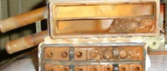
Early cars were equipped with mounting blocks with cylindrical type fuses.
Currently, mounting blocks with pin-type fuses are used, which have more reliable contact in the connector.
| № | A* | A** | Purpose |
| 1 | 8 | 10 | Heater motor Reversing lamps Rear window heating indicator Rear window heating relay (winding) Rear window wiper motor (2104) Rear window washer pump motor (2104) |
| 2 | 8 | 10 | Windshield wiper and washer motor Motor for headlight cleaner and washer Windshield wiper relay Headlight cleaner and washer relay |
| 3 | 8 | 10 | Spare |
| 4 | 8 | 10 | Spare |
| 5 | 16 | 20 | Rear window heating element and heating relay |
| 6 | 8 | 10 | Cigarette lighter Socket for portable lamp Watch |
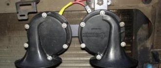
| 7 | 16 | 20 | Sound signals Radiator cooling fan relay (contacts) Radiator cooling fan motor |
| 8 | 8 | 10 | Hazard warning switch with warning lamp Relay-breaker for direction indicators and hazard warning lights Turn signal indicator (in hazard warning mode) Direction indicators (in hazard warning mode) |
| 9 | 8 | 10 | Generator voltage regulator |
| 9 | 8 | 7,5 | Rear fog lamps and their indicator |
| 10 | 8 | 10 | Turn signals (in turn signal mode) Turn signal interrupter relay Turn signal indicator Pneumatic valve control system Fuel reserve indicator Parking brake indicator Insufficient oil pressure indicator in the engine lubrication system Coolant temperature gauge Emergency indicator of the working brake system Battery charge indicator Carburetor choke indicator Electric fan relay (winding) Generator excitation winding (generator 37.3701) |
| 11 | 8 | 10 | Interior lamp Luggage compartment lamp |
| 12 | 8 | 10 | High beam headlights (right headlight) Headlight wiper/washer relay (relay coil) |
| 13 | 8 | 10 | High beam headlights (left headlight) High beam indicator |
| 14 | 8 | 10 | Front side light (left headlight) Tail light (right light) License plate lights Side light indicator |
| 15 | 8 | 10 | Front marker light (right headlight) Tail light (left light) Cigarette lighter lamp Instrument lighting lamp Glove compartment lamp Clock (lighting lamp) |
| 16 | 8 | 10 | Low beam headlights (right headlight unit) Relay for windshield wipers and headlight washers (relay coil) |
| 17 | 8 | 10 | Low beam headlights (left block headlight) |
| 18 | — | Spare | |
| 19 | — | Spare | |
| 20 | — | Spare | |
| 21 | — | Spare | |
| Relay | |||
| K1 | Relay for turning on the heated rear window (904.3747-10 / 2105-3747210-18*, 2107-3747210-12**) | ||
| K2 | Headlight cleaner and washer relay (904.3747 / 2105-3747210-08*, 2107-3747210-02**) | ||
| K3 | Relay for turning on sound signals (904.3747-10 / 2105-3747210-18*, 2107-3747210-12**) | ||
| K4 | Relay for turning on the electric cooling fan ( not used since 2000 ) (904.3747-10 / 2105-3747210-18*, 2107-3747210-12**) | ||
| K5 | Headlight high beam relay (904.3747-10 / 2105-3747210-18*, 2107-3747210-12**) | ||
| K6 | Relay for low beam headlights (904.3747-10 / 2105-3747210-18*, 2107-3747210-12**) | ||
* Mounting block with finger fuses
** Mounting block with blade fuses
Additional fuse block (injector)
| № | A | Purpose |
| 1 | 15 | Main relay |
| 3 | 15 | Injection system power supply circuit (non-switchable voltage input) |
| 4 | 15 | Electric fuel pump relay |
| Relay | ||
| 2 | Main relay | |
| 5 | Electric fuel pump relay | |
| 6 | Cooling fan relay | |
Additional fuse for headlight cleaner
Additional headlight wiper fuses (2A rating) protect the motor windings. They are installed on the supply wires next to the gearmotors.
To check and replace faulty fuses, unscrew the fuse cover.
Fog light circuit fuse
| To check and replace the fog light circuit fuse, pry it up with a screwdriver and remove the two middle switches from the radio panel. |
Using a screwdriver, we press in turn the two fasteners securing the lower insert of the radio panel.
Ignition relay and hazard warning and turn signal relay
Both relays are installed in the passenger compartment on the front panel behind the instrument panel. The ignition relay (113.3747-10 or 90.3747-10) and the hazard warning and turn signal relays (23.3747 or 231.3747) have a bracket for direct mounting on the body.
Using a 10mm socket, unscrew the relay mounting nut.
The relay to be replaced is disconnected from the block.
We fix the new relay in place by placing the ground wire under the nut.
Starter relay
The starter relay is installed in the engine compartment on the right mudguard.
We remove the wire block from its terminals, use a “10” wrench to unscrew the fastening nut and change the relay.
Windshield wiper relay
Using a screwdriver, remove the left side trim. For its subsequent installation, two new fastening buttons will be required.
Using a Phillips screwdriver, unscrew the two self-tapping screws securing the relay.
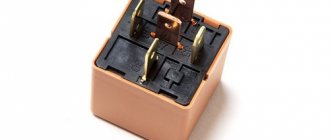
Relay block with four terminals (instrument panel removed for clarity).
Video for the article
FUSE BLOCK VAZ 2104 - 2105 - 2107 - VIS Fuses VAZ 2107. Pinout.
Old style block. Fuse box VAZ 2105 - 2107 new model there is no charging and the reason VAZ 2107, fuel pump relay starts and stalls Turn relay VAZ - 2107 (classic) - replacement Problems with the wiring and mounting block on the VAZ-2107. I can’t understand what the point is. Source
How to determine the lack of battery charge on a VAZ 2105
The easiest way to determine the lack of charging is using the car’s instruments, that is, the charging indicator lamp and the sensor (voltmeter) on the instrument panel. The sensor arrow should be in the green sector, and the battery lamp should not light up when the engine is running. Otherwise there is no charging.
But the best way is to check the voltage on the battery with a multimeter. When there is a charge, the voltage on it lies in the range of 13.6-14.2 V, and when there is no charge, it will only have its own voltage of 12 V (± 0.6 V). Under no circumstances remove the terminals from the battery to check to avoid damage to the RR, ECU and other electronic devices on your car.
To troubleshoot battery charging problems, you must use the following tools:
- control lamp 12 V;
- multimeter with a measuring range of up to 60 V AC and DC voltage;
- flat blade screwdriver;
- shaped screwdriver with a Phillips blade;
- pliers;
- knife;
- emery cloth.
How to solve a problem
The procedure for finding the reason why the generator does not charge the battery:
- Check to see if the accessory drive belt (or alternator belt) is broken. If the belt is intact, check its tension.
- If the belt tension is normal, but the warning light is still on, check that the wiring harness block and the positive wire terminal are securely connected to the generator. Please note that wires may be broken or broken within the insulation.
- Check the reliability of the wire connections to the battery terminals.
- Check the integrity of the generator fuse in the engine compartment mounting block. Replace the blown fuse if necessary.
- If, after all the measures taken, the charging lamp continues to light while the engine is running, then most likely the generator is faulty (for example, the voltage regulator is faulty
Diagnostics and repair work
The diagnostic measures necessary to identify problems with the battery not charging are carried out in the following order:
- you should stop driving and turn off the engine;
- lift the hood and conduct a visual inspection of the belt;
- Check the belt tension using a screwdriver or other tool. The normal deviation is 12-17mm;
- If the belt is loose, tighten it. To do this, pick up a 17mm wrench and unscrew the mount of the generator to the bracket. Using a screwdriver, move the unit to the side away from the cylinders. Tighten the fastener and recheck the tension;
- Check for contact between the battery and the alternator using a tester. This can be done by attaching the device to the positive on the battery and the terminal with the abbreviation “30” located on the installation. If the tester does not indicate the presence of contact, replace the cable;
- Using a voltmeter, obtain voltage data at the battery terminals. The normal indicator is 11-12 volts, in working condition - 13.5-14 volts.
If the data obtained is not comparable with normal values, the breakdown should be looked for in the functional components of the generator set, after removing it from the machine.
Alternator belt tension
Tensioning the generator drive belt is quite simple. To do this, you need to unscrew the fastening that mounts the unit to the corresponding bracket, using a 17 key. Using some kind of pry bar of a suitable size, move the generator towards the cylinders. Next, you need to tighten the fastener, and then perform another tension check. The normal deviation of a tensioned belt ranges from 12mm to 17mm.
Video belt tension
More information about tensioning the alternator belt is described in this video:
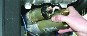
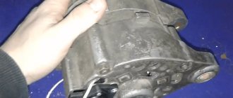
Dismantling the generator
In case of breakdowns in the rectifier, stabilizer or windings, the generator set must be dismantled. This can be done according to the following step-by-step instructions:
- open the hood, disconnect the wires coming from the unit to the battery;
- using a 17mm wrench, unscrew the nut at the place where the unit is attached to the bracket;
- move the generator into the cylinder area using a screwdriver or a suitable pry bar;
- remove the belt;
- disconnect the terminal block;
- unscrew the nut from the terminal under the abbreviation “30”, then move the wires to the side;
- unscrew the nut that secures the generator housing to the bracket. Remove the fastening bolt;
- Remove the generator set by sliding it to the bottom of the vehicle.
Next, you can carry out diagnostic and then repair work to replace the functional elements of the generator.
Video of generator removal
For more information on how to remove the generator from a VAZ-2107 car, see this video:
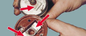
Checking the stabilizer rectifier module and windings
To carry out diagnostic work to check the operability of the rectifier, you should prepare a multifunction tester and two pieces of cable with clamps. Next, perform the following steps:
- set the tester to the mode for obtaining data on the resistance indicator;
- look at the resistance between the terminal with the abbreviation “30” and ground. If the indicator is close to zero, there is a short circuit in the rectifier windings or a breakdown of its silicon diode;
- Check positive directional silicon diodes for breakdown. The tester is connected to the terminal with the abbreviation “30” and to any bolt. If the resistance approaches zero, there is a breakdown;
- check the functionality of the negative silicon diodes by attaching the tester probe between the fixing bolt of the device and its body. A breakdown can be concluded if the resistance indicator is zero.
This concludes the diagnostic work. If problems occur, the rectifier should be replaced.
Generator repair
If the generator set has been dismantled and problems are found in its component parts, work should be done to replace them. Repair of the VAZ-2107 generator is carried out as follows:
- fix the impeller with a screwdriver;
- unscrew the fixing bolts;
- remove the pulley parts;
- unscrew the bolts securing the cover. Take out the pin;
- use a hammer to knock off the stator cover;
- remove the bushing located under the front cover, which also needs to be removed;
- knock out the rotor with gentle blows of a hammer;
- unscrew the nuts securing the rectifier to the winding terminals;
- unscrew the nut with the abbreviation “30” and remove the washer;
- replace structural elements;
- assemble the device;
This completes the work of replacing generator parts.
Video repair of VAZ 2107 generator
For more information about generator repair, watch the following video:
The VAZ 2105 battery has boiled - what to do?
There are several reasons why batteries boil. Let's consider them in order of importance:
- Recharging the battery
- Short circuit of cans
- Sulfation of plates
- Electrical system overload
- Battery polarity reversal
If the battery boils on your car while driving, you must immediately take the following steps:
- turn off the engine;
- open the hood to provide air flow; if the battery has a jacket, remove it; Allow the battery to cool to a temperature below 40 degrees Celsius (easily determined by touching it with your hand); close the hood, start the car and drive to the nearest gas station;
- purchase distilled water and top up to the required electrolyte level;
- if the battery is maintenance-free, topping up can be done through the gas outlet;
- if the repair kit contains a multimeter, measure the voltage on the battery with the engine running; if the voltage exceeds 15 Volts, disconnect the thick wire of the generator, carefully insulating it and securing it to the nearest body element;
- Continue driving to the parking or repair site, turning off, if possible, all additional comfort devices (stove, car radio, air conditioning and others).
Electrical diagram of the VAZ-2107 car
Designations on the diagram: 1 - block headlights; 2 — side direction indicators; 3 - battery; 4 — starter activation relay; 5 — carburetor electro-pneumatic valve; 6 — carburetor microswitch; 7 - generator 37.3701; 8 — gearmotors for headlight cleaners*; 9 — fan motor activation sensor; 10 — electric motor of the engine cooling system fan; 11 — sound signals; 12 — ignition distributor; 13 — spark plugs; 14 — starter; 15 — coolant temperature indicator sensor; 16 — engine compartment lamp; 17 — low oil pressure indicator sensor; 18 — low brake fluid level indicator sensor; 19 — windshield wiper gearmotor; 20 — carburetor electro-pneumatic valve control unit; 21 — ignition coil; 22 — electric motor of the headlight washer pump*; 23 — electric motor of the windshield washer pump; 24 — mounting block; 25 — windshield wiper relay; 26 — hazard warning and direction indicator relay; 27 — brake signal switch; 28 — reverse light switch; 29 — ignition relay; 45 — cigarette lighter; 46 — hours; 47 — instrument lighting switch; 48 — diode for checking the serviceability of the warning lamp for insufficient brake fluid level; 49 — fuel level indicator; 50 — fuel reserve indicator lamp; 51 — speedometer; 52 — indicator lamp for turning on the direction indicators; 53 — indicator lamp for closing the carburetor air damper; 54 — battery charge indicator lamp; 55 — carburetor air damper closed indicator switch; 56 — instrument cluster; 57—econometer; 58 — lamp switches on the rear door pillars; 59 — coolant temperature indicator; 60 — tachometer; 61 — parking brake indicator lamp; 62 — low oil pressure indicator lamp; 63 — indicator lamp for high beam headlights; 64 — indicator lamp for turning on external lighting; 65 - voltmeter; 66 — parking brake indicator switch; 67 — external lighting switch; 68 — rear window heating switch with backlight; 69 — rear fog light switch with on indicator*; 70 - fog light circuit fuse; 71 — ceiling****; 72 — rear lights; 73 — sensor for level indicator and fuel reserve; 74 — pads for connecting to the rear window heating element*; 75 — license plate lights. The order of conditional numbering of plugs in the blocks: a - headlight units, headlight and windshield wipers, windshield wiper relay, carburetor electric pneumatic valve control unit; b - mounting block and three-lever switch; c — hazard warning and direction indicator relay; 30 — ignition switch; 31 — three-lever switch; 32 — alarm switch; 33 — plug socket for a portable lamp**; 34 — heater fan switch; 35 — additional resistor of the heater electric motor; 36 — indicator lamp for turning on the heated rear window; 37 — warning lamp for insufficient brake fluid level; 38 — signaling unit; 39 — heater fan electric motor; 40 — glove box lighting lamp; 41 — lamp switches on the front door pillars; 42 — switches for warning lights of open front doors***; 43 — alarm lights for open front doors***; 44 — connecting block; d — rear lights (numbering of pins in order from the edge of the board); d - hazard warning switch.
* Installed on parts of manufactured vehicles.
Questions from readers
And now I would like to answer questions from our readers!
The lamp does not light, the voltmeter needle remains at zero when the ignition is turned on.
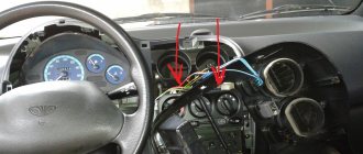
We check the wires on the generator to see if the wire has come loose from terminal “61”. If everything is normal there, you need to check whether there is a “plus” on this wire using a test lamp, an indicator screwdriver or a multimeter.
If there is a “plus” , we check the “tablet” (aka “chocolate”) and the generator. There is no “plus” - you will have to remove the instrument panel and check the lamp. Replace the burnt out one.
Let's start the engine . The control lamp should go out, the voltmeter needle goes into the green sector and is located from the middle to the right edge (photo). If everything is so, then most likely the generator is working normally .
The lamp does not light up, the voltmeter needle shows normal
Check fuse No. 10 in the mounting block. 99% of the time it will be burnt out. In this case, all other lamps on the instrument panel will also be de-energized. Replace it with the same one and test again. If the fuse burns out again, you need to look for the cause, that is, a short circuit. We check whether the wires from the generator are disconnected, whether the insulation is frayed somewhere, etc.
The lamp remains on or dims slightly
If you give it gas, it goes out at high speeds and lights up again when they decrease. The voltmeter needle is in the white sector and goes to the edge of the green when the speed increases. The generator output is faulty. The same conclusion if the lamp continues to light at any speed, and the voltmeter needle is in the white sector and even goes to red.
If the generator seems to be working, but the battery is gradually discharging, we will perform another check. We start the engine, turn on the heater fan and low beam, take the key to “10” and, loosening the negative terminal of the battery, remove it. An idling engine (about 900 rpm) should not stall. If the engine stops, put the terminal back in place and start it again. While holding the speed at 1200-1500, remove the terminal again. Has the engine stalled again? Then turn off the headlights, leave the heater fan on and repeat the test. Now the engine with the negative terminal disconnected from the battery continues to run. output works, but does not produce the required current; it needs to be repaired.
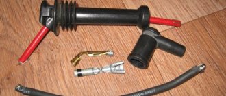
Let's consider replacing the brushes of the VAZ 2107 generator without removing it from the car.
The first thing you need to do is disconnect the negative terminal of the battery, then pull out the brush holder output connector. The brush holder is located on the end surface (the opposite side from the pulley on which the generator belt is placed) on the right side. It consists of two parallel metal pins and plastic holders. Next, you need to find the screw securing the brush assembly and unscrew it. The assembly should now easily detach from the main part.
We check the protrusion of the brushes and their uniform wear. The working surface (length) of the brushes must be at least 12 mm; if less, then the VAZ 2107 generator brushes must be replaced. In addition, you should check the ease of movement of the metal structures in the holder; they should not rub or jam. If free movement does not occur, then it is recommended to also blow the generator rotor with compressed air.
Installation of new VAZ 2107 generator brushes occurs in the reverse order, taking into account a small nuance. For proper operation of the brush assembly, the protruding contact should be recessed slightly into the assembly and only then begin to screw the assembly to the generator.
Let's summarize:
As you can see, there are many reasons why the battery does not have charge. At the same time, a number of problems when the battery does not charge are common to different cars (for example, a VAZ 2107 is not charging or the battery of a foreign car is not charging). Moreover, some of them can be easily detected and eliminated with your own hands. The main thing is to determine why the battery is not charging, after which appropriate measures are taken.
Finally, we note that even ordinary car enthusiasts usually do not have problems with cleaning the terminals and restoring the integrity of wires and contacts. If the problem is with the generator, if you do not have the skills to repair it, it is only recommended to dismantle it yourself and then transfer the generator to a specialized service for repair. This will allow you to avoid common mistakes that are made when repairing a generator with your own hands, and also obtain a guarantee for the repaired device.
Source
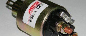
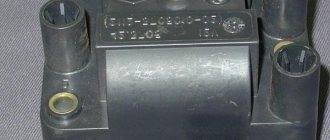
Where is the Charging Relay for VAZ 2107 Injector
As a rule, problems with starting the engine are observed in the winter season, if the VAZ-2107 is left to spend the night on the street. This can happen for a variety of reasons, but when the battery discharge indicator flashes on the instrument panel, the first thing you need to suspect is a problem with the charging relay. This kind of trouble is most often encountered by those drivers who do not regularly carry out preventive maintenance on their iron horse.
How to replace the charging relay on a VAZ-2107 car, and where exactly is it located? This article talks about this.