Faulty vehicle wiring leads to serious problems during the operation of the car - from incorrect operation of sensors and devices, on-board computer and automation to complete failure of expensive electrical equipment. Remember that a short circuit in the on-board circuits can lead to a fire in the vehicle. Therefore, faults in electrical equipment and electrical equipment should be eliminated immediately when they are detected - there is no need to put off repair work “on the back burner”.
You can repair car electrical wiring either yourself or at a car service center. The main difficulty lies in finding faults - breaks, failed relays, fuses and blocks, breakdowns of individual elements and auto electrical devices.
Common machine electrical faults
Auto electrics include various systems, parts, devices and elements of the vehicle - the ignition system, battery and generator, on-board computer circuits, fuses, sensors, relay blocks, various electronic sensors, auto lights, as well as auto electronics - climate system, audio system, automation and systems security. It is necessary to take into account the peculiarities of automotive electrical wiring in order to quickly find and eliminate a malfunction in the on-board network.
Common electrical problems include:
- Battery failure. This may be a consequence of insufficient electrolyte density, damage to the case with electrolyte leakage, destruction of the plates, or significant oxidation of the battery terminals.
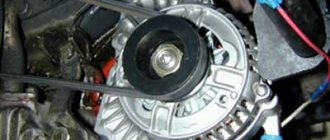
- Generator breakdowns - winding breaks, problems with the voltage relay, failure of the diode bridge, wear of brushes and bearings.
- Problems with the ignition system. We are talking about malfunctions of spark plugs, ignition coils, an open circuit or oxidation of the contact group.
- Deformations of electrical wiring - oxidation at connection points (inputs, contacts, terminals), breaks, destruction of wire insulation, short circuit of wiring, violation of the integrity of twists.
- Failure of electronic components. This refers to malfunctions of various electrical devices in circuits, devices and electrical equipment of a car (conductors, diodes, fuses, capacitors).
Why do you need vein coloring?
Color coding of wires allows you to quickly figure out what each wire is responsible for
Novice craftsmen who are just learning the basics of electrical engineering cannot immediately determine whether the white wire is a plus or a minus. Coloring is important in identifying cores and is called marking.
Color marking of conductors is a necessity, allowing the master to quickly figure out what each core is responsible for. With its help you can understand what color the neutral wire is and where the phase is located. It also makes electronic circuits easier to read.
It is especially important to observe color markings when connecting to meters, machines, and devices. Without painting, it is difficult to figure out which device may have failed and which circuit it is connected to.
Manufacturers paint cables in certain colors established by the rules of electrical installations PUE. They strictly regulate which markings should be used for a particular core.
In addition, it is important to understand that the positive and negative contacts in the DC circuit have their own colors. What color the positive wire is is also determined by the rules.
In the case of an unmarked cable of the same color, a label with information can be placed on the ends of the product (for example, on a heat-shrinkable tube).
How to check wiring
You can diagnose electrical equipment using a voltmeter, ohmmeter or multimeter, or special diagnostic stands. Computer diagnostics are also carried out, during which error codes and main indicators of the machine’s on-board network are read. To independently check circuits and troubleshoot electrical faults, one multimeter or signal lamp is enough.
We use a multimeter
Fuses in the on-board network are considered the “weakest” link in terms of durability. In case of emergency situations (for example, in the event of a short circuit), the safety elements “take the blow”, protecting the rest of the electrics and electrical equipment of the machine. Fuses cannot be restored and must be replaced during repairs.
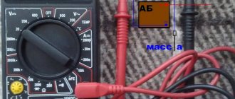
Checking the voltage
Before checking the wiring in the car, it is necessary to measure the voltage of the electrical circuit between individual components and electrical equipment. You can call like this:
- Set the multimeter to voltmeter mode.
- Connect one probe of the measuring device to the “minus” of the battery or to the ground of the machine.
- Connect the second probe to the supply wire of the circuit.
If a certain value appears on the device display, then there is voltage in this section of the electrical circuit. You can compare the values with those required according to the vehicle's owner's manual.
Looking for a short circuit
After measuring the voltage, search for short circuits. This will require either a multimeter or a pilot light. As for the lamp, if the wiring is in good condition and there is no short circuit, it should not light up.
A short circuit in the wiring, as well as a lack of voltage (zero or infinite resistance in the electrical circuit), indicates a malfunction in one of 2 components:
- Consumer - electrical equipment, devices, fuses, blocks.
- Wiring – broken or shorted wires, poor wiring contacts at the point of connection with the consumer.
Checking for a short circuit can also be done in voltmeter mode. To do this, it is necessary to remove all fuses in the area being tested and connect the probe to the terminals of the fuse element. The value “0” on the screen indicates the presence of a short circuit in the circuit. If, when you try to move the wires, voltage appears in the circuit, then the short circuit is caused by the wiring and the wires will need to be replaced.
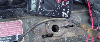
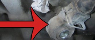
Checking the quality of grounding
Cars use a single-wire wiring diagram - this means that the “minus” goes to the ground (body) of the car. However, corrosion of metal parts, their oxidation and destruction, “loosening” lead to grounding failure and, as a consequence, to disruption of on-board circuit contacts.
Checking the grounding, as well as other electrical elements of the car, is carried out using a multimeter. The procedure is as follows:
- Disconnecting the battery.
- Connecting one multimeter probe to the body (metal parts) of the car.
- Connecting the second probe to the grounding element or wiring connection.
The value displayed on the device screen should be compared with the factory data (car operating manual). If the values diverge greatly, then it is necessary to restore the grounding - clean the metal at the connection point, check the reliability of the fastening.
Checking the integrity of the circuit
The connection of wires in the electrical circuit of cars is one of the most vulnerable points in the entire electrical system of the car. In addition to the destruction of insulation, loss of integrity and breaks at the connection points, oxidation of the contacts also often occurs here. Defects can be determined not only using a measuring device, but also visually. If the integrity of the circuit is broken precisely at the connection point, then soldering of wires with connectors will be required. Otherwise, you need to find the damaged area, which will require a signal lamp or multimeter.
How to determine ground, zero and phase on wires if there are no markings
It is more difficult to determine in practice than in theory. Not all manufacturers comply with the standards. Therefore, when laying a two-phase 220 V network with grounding, you have to use a VVG cable with blue, brown and red colors. Combinations may be different, but without complying with regulatory requirements.
For your information. In old wiring from “Soviet times” there is no color marking. Identical white (gray) shells do not allow the purpose and correspondence of the lines to be known by simple visual inspection.
To avoid problems, it is recommended to carry out installation work using the same type of cable products. When color coding is not available, it should be created at the joints using insulating tape or heat shrink tubing. The latter option is preferable, as it is designed to maintain integrity for a long time.
Below are methods for determining phase and neutral wires with the advantages and disadvantages of each option. In any case, first clarify the network parameters. In old houses, for example, a two-wire connection scheme with a single working and grounding conductor is often used.
The figure shows a modern network with separate grounding and working zero connections. It is possible to connect three- and single-phase loads.
Determining the phase using an indicator screwdriver
Touching the tip of such a device to the phase wire closes the current circuit. This is accompanied by the warning lamp or LED lighting up. A built-in resistor limits the current to a safe level.
Advantages of the indicator:
- minimum cost;
- compactness;
- reliability;
- durability;
- autonomy;
- good protection from adverse external influences.
The disadvantage is the limited measurement accuracy. Under certain conditions, false positives cannot be ruled out.
Determination of ground, zero and phase using a test lamp
To reproduce this technology, you need to prepare a simple design. An incandescent lamp designed for the appropriate mains voltage is screwed into a standard socket. Connect wires of sufficient length to perform work operations in a specific location.
Next, connect one of the wires to the known zero line. Others sequentially check other cable cores. Lighting of the lamp indicates the presence of a phase.
Using a measuring device
When checking a 220 V household network, you do not need to know how to determine the polarity. The power supply is organized using alternating current, so set the multimeter switch to the appropriate position. Touching the phase-zero (phase-ground) wires with the probes is accompanied by an indication of the corresponding voltage (≈220 V). The potential difference between the neutral conductor and ground is minimal.
For your information. When checking an old two-wire circuit, one of the probes touches the reinforcement in a concrete slab, a radiator of a heating system, or another grounded element of a building structure.
When switching to constant voltage, the multimeter will show where the plus and minus are. In the absence of reliable information about the electrical parameters in the circuit, they begin with the maximum measurement range with a sequential transition to smaller values with insufficient accuracy.
Such a “device” is useful for testing DC circuits in the absence of specialized measuring instruments. Bubbles near the negative wire are the release of hydrogen during the electrolysis reaction. The area near the plus will take on a greenish tint after a few minutes.
Using LED
You can create a control device with your own hands by analogy with an indicator screwdriver. Instead of a light bulb, install AL 307 or another LED with similar characteristics. A 100-120 kOhm resistor with a power of 1-2 W is added in series to the circuit.
Car electrical wiring repair
You can check and restore the car's electrical wiring yourself or at a car service center. After identifying faulty areas where there is damage to the wires, a short circuit or a break, they are soldered or completely replaced. Conventional twisting followed by crimping is not a full-fledged repair, but only a temporary measure - take this into account if you do not have the opportunity to solder the break points.
Wires are selected with the same characteristics as the existing damaged ones (resistance, metal). You should not install too long wires with a “reserve”; twisted open wiring under the influence of negative factors (temperature changes, moisture, dirt) is destroyed faster - this can lead to a short circuit. When replacing wiring harnesses with connectors, make sure that the contact groups are completely free of oxidation before work.
Mounting blocks located in the engine compartment are also considered a vulnerable element of a car's electrical system. Due to the destructive effects of temperature and moisture changes, damage to the protective coating and subsequent defects in tracks, connectors for connecting wiring harnesses, relays, and capacitors are possible. Repair of mounting blocks, consisting of circuit boards, fuses and electrical components, includes soldering to restore tracks and coating with a special protective varnish, as well as replacement of faulty elements and wiring, connectors, cleaning contact groups from dirt and oxidation.
Replacing car wiring
When replacing wiring in a car, be sure to turn off the power, including disconnecting the battery. Of course, this is not a precaution against electric shock, but protection of the vehicle’s electrical equipment from possible short circuits that may occur during repair work.
Sometimes the replacement can be completed in 10-15 minutes - for example, if the wires of the “battery-generator” supply circuit are damaged. If the integrity of the wiring in the cabin is damaged, there are problems with grounding, or a short circuit in the on-board computer circuit, then the work will take much more time. And the main thing here is not to make a mistake, since incorrectly connecting the wires (for example, if the polarity is reversed) can cause a short circuit, damage to expensive electrical equipment and even a fire. If you do not have experience in electrical engineering and electrical installation work, it is better to contact a specialized service for the services of a professional auto electrician.
How to check current leakage on a used car with a multimeter
The check includes:
- Turn off the engine, remove the key. Close the doors, but open the windows - the battery will not work continuously, and the car may be locked with a central lock.
- Make sure that the additional lighting and radio are turned off.
- Remove the negative terminal from the battery.
- Place one probe between the negative terminal and the negative terminal of the battery - the device will show the leakage current value.
The normal value is 15-70 mA. If the numbers are higher and you and the seller have time, try to find the reason. To do this, also connect a multimeter, then start removing the relays and fuses one by one.
The readings have returned to normal - you have found the cause of the current leak. Perhaps further repair or replacement of a part, or even the entire wiring, will be required. You can confidently ask the car seller for a discount or refuse the purchase altogether.
There may be several reasons for the leak. The following may be involved:
- battery;
- sensors;
- high voltage wires;
- generator.
Each element can be checked using a multimeter.
Performing markings for different types of currents
Let's figure out what criteria electrical cables are divided into.
Classification of electrical cables
First of all, you need to decide on their colors and characteristics:
- Number of wires in the cable. This parameter determines the scope of application of a particular cable. This includes power supply of electrical machines, current transmission of electricity, installation of connections for apartment buildings, as well as other electrical installation work.
- Cable conductor materials are primarily aluminum, copper, or a combination of both.
- Insulating coating. There are many materials available for it, such as plastic, rubber, paper and other dielectrics. The wire may not have insulation. Bare wire is usually used on overhead power lines. Where negative environmental influences are possible, cables equipped with reliable insulation are installed.
By accurately selecting a cable according to its cross-section, the current strength , alternating or direct, for which this wire is intended is determined.
Other characteristics - resistance, power, voltage - also need to be determined when preparing electrical circuit connections.
Color standards
Three-phase alternating current.
Connection of high-voltage wire and bus inputs at 3-phase voltage in the switchgear is carried out according to the following phase color :
- A yellow.
- B green.
- C red.
Most often in everyday life and industry, electric current operates with alternating voltage.
But there is also an application for electrical installations at constant voltage: In production and construction, such voltage is used to power electric hoists, carts, and loading and unloading tools in warehouses.
Electric transport also runs on DC networks .
Power supply of protection and automation circuits on relay boards of electrical substations.
The cables used for such connections are two-core. They are usually called "plus" and "minus".
The answer to the question - is the phase plus or minus - will be given by the PUE.
The standard colors are:
- the positive pole is painted red;
- minus - blue.
Accordingly, the plus is the phase, and the minus is zero.
The contact marked in the electrical diagrams with the letter M and colored blue will be zero.
If you are connecting a two-wire network to a network with three wires, you need to check that the colors of the supply and connected networks strictly match.
Three-phase wiring color standards
The variety of insulation colors is especially important if the wiring is installed by one organization and operated by another.
Thanks to this, an employee of the second company will always know the location of the “phase” or “zero” without using a voltage indicator or device. When coming into contact with electrical wiring , you should be wary of touching the phase feeder, which risks being fatal. Most likely, in an effort to preserve life and health, such a pronounced, flashy color scheme was used.
How to test a car battery with a multimeter
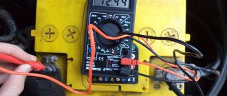
Testing a car battery with a multimeter involves connecting two probes at once. Also turn off the engine before taking measurements.
Place the red probe against the “positive” terminal, the black one against the “negative” terminal. If you mix it up, it’s okay, the device will show the current numbers, just with a minus sign.
Look at the device screen. The normal battery charge ranges from 12.6 to 12.9 volts.
The operation of the battery can also be checked with the engine running. When checking the car battery with a multimeter, you will also find out how the battery works in conjunction with the generator, as well as whether the voltage regulator is working properly.
Normal numbers with the engine running are 13-14 volts. If the multimeter shows less, the battery needs to be charged, or there is a current leak.
Remember: a multimeter will show the battery charge, but will not tell you everything about its operation. There are other devices for this. For example, a load fork.
How to check car sensors with a multimeter
The reason for the “death” of the battery, voltage surges, and unnecessary values on the instrument panel can be various sensors in the car. According to the experience of motorists, 5 types of sensors most often cause problems:
You can understand where they are located from the instructions for the car, on car enthusiast websites, and various forums.
To check your car's sensors with a multimeter, you will also need information about the normal voltage readings specifically for your car. It can also be found in the instructions or on the Internet.
How to correctly determine the polarity on wires in a car
If the voltage on the car is checked, the course is set to search for a constant one. 20W is the correct setting if you are testing the battery. Therefore, you need to adjust the dial to the desired range/setting and connect the probes to whatever component you want to get a reading for.
How to check a headlight with a multimeter
To check the headlight wiring, you need to find the ground wire. There are 2-4 wires coming from the connector that connects to the light bulb. Where there are two or three wires, only one of them is ground, while four-wire connectors will have two grounds.
ABS sensor
It is checked by two parameters: voltage and resistance.
To start measuring, select the appropriate mode on the multimeter. If you want to know the resistance value, for most the norm is 1.2-1.8 kOhm. Connect the device to the sensor and start taking measurements. At the same time, shake the wires going to the element. If the numbers on the screen change and become higher or lower than normal, there is a problem with the sensor.
Measuring voltage is a little more difficult - this can only be done with a jack or in a car service on a stand. You need to spin the car wheel to 40-50 rpm and monitor the multimeter readings. On any machine it should output 2 volts.
Wire colors in electrical wiring
Identification of wires by color is very convenient, especially when their installation and connection is done by one person, and another person will maintain and repair them.
Each color of the electrical conductor determines its purpose in the cable according to a specific standard, which has been changed several times since the times of the USSR.
Today, conductors in AC electrical installations with a solidly grounded neutral and voltages up to a thousand volts have very specific markings.
Color of zero working and zero protective wires
This color combination is used only for marking neutral protective pinch conductors.
Oxygen sensor
Determines whether oxygen remains in the exhaust gases. Before taking measurements, also inspect it - it may be damaged and a multimeter will not be needed at all. Then the element just needs to be replaced.
If everything is in order, measure the voltage and resistance as with the ABS sensor. The algorithm is the same. Start the car and watch the device. After start-up, the numbers 0.1-02 volts will appear on the screen. When the car warms up, the device will show up to 0.9 volts. If you didn’t notice that the indicator has changed, the sensor is most likely faulty.
If the voltage test is successful, find out the resistance readings. The norm ranges from 10 to 40 ohms.
Knock sensor
Determines the shock wave during fuel combustion. The resistance indicators for each car are individual - look for information in different sources.
It's a little easier with tension. First remove the sensor. Connect the plus probe to the signal wire, the negative probe to ground, closer to the mounting bolt. Next comes the fun part - hit the sensor against a wall, chair or table. This is the only way the multimeter will record the voltage reading. The norm on most cars is from 30 to 40 millivolts.
How to check high-voltage wires on a car with a multimeter
If you feel a loss of car power, see increased fuel consumption, the car shakes, and the idle speed fluctuates, it’s time to check the high-voltage wires. More precisely, measure the resistance in them. Remember the procedure:
- disconnect the wires from the machine or disconnect one wire on both sides;
- turn the device into ohmmeter mode and place the probes on both sides of the wire.
The normal resistance value is 6-10 kOhm. If the device shows less, down to zero, do not be alarmed. The multimeter numbers are influenced by many factors, for example:
- quality of wire insulation;
- length;
- presence of microdamages;
- wire type.
If your car's performance is outside the normal range, it is better to contact a car service center, where the resistance will be measured with professional and more accurate instruments.
Color of wires plus (+) and minus (-) in DC networks
In some areas of the national economy, DC networks are used:
- for operational protection circuits and automation power supply at electrical substations;
- in electrified transport;
- in construction, industry, when storing materials.
In such networks, only two conductors are used: positive and negative buses. There is no phase or neutral conductor in them.
Marking of wires and buses for DC networks:
- red color is used for positive charge wires;
- blue – for tires and wires with a negative charge;
- Blue color indicates the middle conductor.
If the DC network is created from a three-wire network (by branching), then the color of the positive conductor is the same as the positive conductor of the three-wire circuit.
How to check a generator on a car with a multimeter
Checking the generator is similar to measuring other elements of the car that cause current leakage.
- Traditionally, turn off the ignition, take out the key, turn off the radio, and so on.
- Connect the multimeter to the battery.
- Measure the voltage. A fully charged battery will produce between 12.5 and 12.9 volts.
- After this, start the engine, turn on the heated windows, seats, heater, and low beam.
Instead of an afterword
When buying a used car, it is useful to know how to find an electrical leak and understand its cause. Take a multimeter to inspect your car - you will save yourself from unpleasant surprises, such as a suddenly dead battery, power surges or burnt wiring.
For the same purpose, check the car's history. This can be done directly during a conversation with the seller. It’s convenient to use the Autocode service - monitor information from 13 sources at once: traffic police, RSA, EAISTO, banks, tax and other services. The verification will take 5 minutes.
Afterwards you will find out the actual mileage, number of owners, history of fines, as well as information about theft, participation in an accident, restrictions on car registration and much more. Be carefull!
Having fully studied the online report, it is still worth taking a closer look at the technical nuances of the car when purchasing. And if you are not confident in your knowledge, or it is not possible to go for an inspection, order an on-site inspection service. The specialist will conduct a diagnosis for you and make a detailed conclusion from a professional point of view.
How to make an indicator to check the wiring in a car. How to find the positive wire in a car
How to Determine and Check Polarity Using a Multimeter
Accurate knowledge of the polarity of an electrical appliance is extremely important. After all, if you connect electrical equipment with incorrect polarity, it may either not work or be completely damaged.
In most cases, the “plus” and “minus” of wires and contacts in such devices are indicated by letters, symbols or colors (on the case near the contacts there is a “+” and “-” marker, and the wires are black for minus and red for plus) . But sometimes it happens that it is not possible to visually determine the poles. To do this, you can use either an ordinary polarity tester or improvised means.
Determining polarity with a multimeter
Sometimes it happens that a new electrical device that needs to be connected does not have polarity markings, or it is necessary to re-solder the wiring of a damaged device, and all the wires are the same color. In such a situation, it is important to correctly identify the poles of the wires or contacts. But if you have the necessary instruments, a logical question arises: how to determine the plus and minus of an electrical appliance with a multimeter?
To determine the polarity, the multimeter must be turned on in the mode for measuring direct voltage up to 20 V. The wire of the black probe is connected to the socket marked COM (it corresponds to the negative pole), and the red one is connected to the socket with the VΩmA marker (it is, accordingly, a plus).
After this, the probes are connected to the wires or contacts and the device, the polarity of which needs to be determined, turns on. If the multimeter display shows a value without additional signs, then the poles are determined correctly, the contact to which the red probe is connected is positive, and the contact to which the black probe is connected will correspond to the minus. If the multimeter shows a voltage value with a minus sign, this will mean that the probes are connected to the device incorrectly and the red probe will be a minus, and the black probe will be a plus.
If the multimeter used to measure is analog (with an arrow and a display with gradations of values), if the poles are connected correctly, the arrow will show the actual voltage value, but if the poles are reversed, then the arrow will deviate in the opposite direction relative to zero, that is, it shows a negative current value.
Determination of polarity by alternative methods
If it happens that you don’t have a multimeter at hand, but you need to find the polarity, you can use alternative and “folk” means.
For example, speaker wiring charges are checked using a 3-volt battery. To do this, you need to briefly touch the wires connected to the battery to the speaker terminals. If the cone in the speaker begins to move outward, this will mean that the positive terminal of the speaker is connected to the positive terminal of the battery, and the negative terminal to the negative terminal. If the diffuser moves inward, the polarity is reversed: the positive terminal is connected to the minus, and the negative terminal to the plus.
If you need to connect a DC power supply or battery, but there are no polarity markings on them, and you don’t have a multimeter at hand, plus and minus can be determined using “folk” methods using
Connecting a car radio
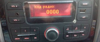
When connecting the radio, you must strictly follow the diagram. To power the car radio, you need to connect the yellow wire to the battery positive. The black wire goes to ground, this is grounding. The red wire is powered from the ignition switch. Ideally, it should be connected so that it is powered only when the key is in the ACC position.
Since installation difficulties arise precisely in the absence of an ISO adapter, all wires must be stripped and then insulated. Stranded copper wires with silicone insulation are ideal. Once the wiring is complete, they can be combined into a standard adapter, but you can also insulate them with the radio wires. The main thing is that the color of the wires of the radio and the car match each other.
There are several other undesirable options for connecting a car radio to a car. Most motorists, not wanting to bother with connecting the yellow wire to the battery, connect it together with the red wire to the ignition switch. This deprives the radio of more power and does not allow you to get high-quality and powerful sound. The same thing happens when the radio is powered from the cigarette lighter.
It happens that the yellow and red wires are connected to the battery. The advantages of this connection are that the radio is always in standby mode and ready for use. However, this method quickly lands him. Therefore, it is worth thinking about what is more important: the operation of the radio independent of the ignition switch or the long-term operation of the battery?
Connecting speakers
The colors of the radio speaker wires have already been described above. Therefore, in accordance with them, you can safely connect any speakers.
Today, almost all car radios are oriented towards 4 speakers: two in front and two in back. It is worth noting that a powerful audio system has a plus and minus output to each speaker. A weak audio system has only a positive output. Therefore, the minus from the column is displayed on the total mass. To get better sound, it is best to observe the plus and minus contacts.
How to find a current leak in a car
Sometimes after the car has been parked for a long time, when you turn it on, you can only hear the clicks of the relay, or the starter still turns on, but turns weakly. All these symptoms indicate that the battery has been completely or partially discharged while parked.
Often the cause of the discharge is headlights or side lights that are not turned off.
This cannot be explained by self-discharge - a serviceable battery takes a long time to discharge, several months - which means that a current leak has occurred, or there is a malfunction in the battery charging system, and the driver, when parking the car, did not know that the battery was not well charged.
Common Causes of Current Leakage
When diagnosing the cause of premature discharge, it is necessary (and this is a general rule for diagnosing any malfunction in a car) to cut off causes that do not indicate a malfunction. Or rather, about inattention to the car. For example, the battery may be old and expired, the terminals may be covered with scale, or the wires may be in poor condition, etc. Often the cause of the discharge is headlights or side lights that are not turned off. If there is no reason to think that the cause of the discharge was one of the above or similar factors, we can establish the presence of a wiring fault and begin searching for the leak.
Acceptable battery current consumption limits
The car has a number of “authorized” permanent consumers of electricity. This could be a clock, memory of an electronic engine control unit, an alarm system, etc. All of them are constantly powered, since, for example, it is not recommended to erase the ECU memory, otherwise the unit will be retrained, remembering the current settings again, and the alarm generally works just at those moments when the engine is turned off and the car is standing still.
It follows from this that current consumption in a parking lot is normal and should have some kind of constant value that can be calculated by adding up the consumption of all consumers. For example, an alarm system can consume about 20 mA, a clock memory - 1 mA, a radio tape recorder - 3 mA, and so on. The total consumption should fluctuate between 50 - 80 mA. This is a small consumption (for example, even one switched-on lamp consumes around 500 mA), and a modern battery cannot be severely discharged by such leaks, even in winter.
If, based on the measurement results, it turns out that the average value of constant consumption is significantly exceeded, it means that there is a leak in the on-board network and it must be eliminated.
How to independently determine the presence of current leakage
There are two main reasons for an intense discharge - the presence of an “unauthorized” current consumer, or a short circuit in the on-board circuit. You can detect the leakage of current absorbed by a constantly working consumer by using a household appliance called a multimeter.
Multimeter
To troubleshoot the problem, the multimeter must be switched to ammeter mode, not forgetting that the current in the on-board network is constant, and the measurement range must be set to 10 Amps.
How to determine wire polarity
You will need
- multimeter, 3 volt battery, indicator screwdriver, test lead.
Instructions
To determine the polarity of the wires coming out of the charger, turn the multimeter into DC voltage measurement mode up to 20 volts, insert the black wire (negative) into the COM jack, and the red (positive) wire into the VΩmA jack. Connect the probes to the terminals of the charger and turn it on. If a minus sign appears on the multimeter display, then the polarity of the connection is opposite, that is, the red probe is connected to the negative terminal, and the black probe is connected to the positive terminal of the charger. If there is no minus sign, the terminals correspond to the probes connected to them.
To check speaker polarity, briefly touch the speaker terminals with wires from a 3-volt battery. When the speaker cone moves outward, the polarity of the speaker terminals matches the polarity of the battery. When moving inward, the polarity of the speaker terminals is opposite to the polarity of the battery.
Power wires in branded car radios are easily distinguished by their color, which always matches its wire. The black color is for the wire connected to ground or the general “minus” of the power, the red wire is the “plus” of the power, it is connected to the ignition switch, the yellow wire also belongs to the “plus” of the power, but is connected to the battery. In any case, the fused wire is the “power plus” of the power supply. When replacing a faulty switch, it is not always possible to de-energize a house or apartment. In this case, an indicator screwdriver will help to identify the phase (dangerous) wire. It will also help if, while carrying out any repair work, you come across an unknown wire. To test cables with identical-looking cores, turn the multimeter into low resistance measurement mode. In case of continuity of the signal wire, a metal cable shield can be used as a common continuity wire. On one side of the cable, connect the wire under test to the screen, and on the other side, connect the black probe to the braid and touching the wires one by one, find the wire shorted to the screen.
Quite often there is a need to check the polarity of a DC source - a battery, a generator or, for example, a rectifier - without the necessary device at hand.
You will need
- - potato;
- - a jar of water;
- - candle.
Instructions
In amateur practice, you can do the following. Dip the two bare ends of the wires connected to the battery terminals into a jar of warm water in which a tablespoon of table salt is dissolved. Then bring them closer until bubbles of hydrogen gas begin to appear at the end of one of the wires. This wire will correspond to the negative pole of the source. Cut a raw potato tuber in half, insert bare (stripped) wires into one of the parts from the cut side at a distance of 15-20 mm from each other. Near the wire connected to the positive terminal of the battery, the surface of the potato will turn green (oxidation process). Third way. Light a regular household candle. Immerse two conductors connected to a higher voltage source into the candle flame. Under its influence, the candle flame will become low and wide, and a thin strip of soot will appear on the wire with a negative charge. In addition, a simple indicator can be made to repeatedly determine the polarity of an unknown source. To do this, you need to take an ordinary glass tube with missing electrodes inside (for example, from a burnt-out electric lamp) and closed with plugs. Inside the tube, pour a solution consisting of one part nitrate, 4 parts water, preferably distilled or boiled, five parts glycerin, mix with one tenth part phenolphthalein and part wine alcohol. It makes sense to use chemical test tubes. Such an indicator can last a very long time, and when a negative charge is placed, a red color will appear. If the current source is alternating, the electrodes will give a pink color. To double-check the polarity, just shake the indicator lightly.
Automotive stores sell lead-acid batteries of direct polarity (all domestic cars are equipped with them) and reverse polarity (installed on some foreign-made cars). Before purchasing a battery, you must accurately determine its polarity.
You will need
Instructions
The service life of any rechargeable battery is limited and, as a rule, is no more than five years. Having worked for the allotted time, the moment inevitably comes to replace the power unit. And if the problem for owners of domestically produced cars is to choose a battery of the appropriate capacity and give preference to a certain brand, then owners of imported cars need to find out the polarity of the battery before purchasing. To achieve this task, the battery is removed from the battery socket and positioned in such a way that when visually inspected from above, its terminals should be at the bottom. Please note that one of them is slightly thinner than the other (it is negative). If the negative terminal is located on the left (bottom) of the battery, then the battery has reverse polarity.
In cases where the thinner terminal on the right is a straight-polarity battery.
To finally make sure that the polarity of the battery is determined correctly, attach a voltmeter to it. In this case, the red probe of the device removes voltage from the thick terminal, and the black probe from the thin one. The reading on the scale without the minus sign confirms the battery parameters being studied.
Video on the topic
note
Installing a battery with incorrect polarity in a car may result in cables being unable to be connected to its terminals.
Sources:
- how to determine battery polarity
When connecting power three-phase, single-phase and signal wires, errors are unacceptable. They can lead to malfunction of equipment, grounding systems and electric shock to operating personnel. Of great importance is the correspondence of the color marking of the cable to the connected circuits.
You will need
- Technical description of the cable
Instructions
To identify wires by color in three-phase wiring, use the following rule.
Modern marking of three-phase cables is as follows: phases A, B, C are marked in white, black and red, respectively. The neutral wire is indicated in blue, and the ground wire is yellow-green. The marking of single-phase network wires uses three colors: white - phase, blue - neutral, grounding is indicated by a yellow-green wire.
If the USB cable is accidentally broken, restore it using the following color coding scheme: the positive power supply corresponds to the red wire, the negative power supply corresponds to the black wire, the white wire corresponds to the negative data wire, and the green wire corresponds to the positive wire.
The most complex colors of wires in multi-core cables. For example, to quickly find the location of damage to the communications of the SBZPU or SBPU cables, you will need to determine the integrity of the cores between adjacent branches of the main cable (as a rule, these types of cables are used on the railway). To clarify the color layout of a specific brand of cable, use the corresponding technical description.
So, for example, if there is a break in the SBZPU or SBPU cable, then you can determine the color of the wire according to the following scheme: Pair 1. The color of core B is blue, core A is white. Pair 2. The color of core B is yellow, core A is white. Pair 3. Core color B is green, core A is white. Pair 4. Core color B is brown, core A is white. Pair 5. Core color B is gray, core A is white. Pair 6. Core color B is red. , conductors A - white. Pair 7. Color of conductor B - blue, conductors A - red. Pair 8. Color of conductor B - yellow, conductors A - red. Pair 9. Color of conductor B - green, conductors A - red. Pair 10 The color of core B is brown, core A is red. Pair 11. The color of core B is gray, core A is red.
Pair 12. The color of core B is red, core A is red.
Video on the topic
Sources:
A light-emitting diode, unlike a light bulb, only works if the polarity is correct. But it is usually not indicated on the device itself. The location of the LED pins can be determined experimentally.
Instructions
Make a device to check the polarity of LEDs. To do this, take a battery compartment with three AA cells, a 1000 Ohm resistor and two probes: red and black. Connect the negative terminal of the battery compartment directly to the black probe, and the positive terminal through a resistor to the red probe. Place the device in a suitable housing. Insert batteries into the compartment. To check the LED, connect the probes to it first in one polarity, and then, if it does not light up, in the other. When a diode is lit, the black probe is connected to its cathode and the red probe is connected to its anode. The resistor in the device is chosen so that the glow is dim, but it is possible to check even the most low-power LEDs. When working with emerald, blue, violet and white LEDs, protect them from static electricity.
Make a case to store the device you made. Provide space for separate storage of probes. This is necessary so that they do not short-circuit with each other when being carried. A short circuit will not damage the device, but if you keep the probes short-circuited for a long time, the batteries will gradually discharge through the resistor.
Having determined the polarity of the LED, do not apply reverse voltage to it in the future. The probability of its failure is small, but it exists.
If you purchased a large number of LEDs of the same type, determine the polarity of only a few of them. Make sure they all have the same pinout. In the future, to save time, determine the polarity of the LEDs before soldering by the shape and length of the leads. But do this only if you are absolutely sure that all diodes are of the same type. Never use LEDs without resistors. Even exceeding the current through such a device by only two times can reduce its service life by almost a hundred times. A tenfold excess will disable it instantly.
Video on the topic
Sources:
At first glance, it makes no sense to indicate polarity on the speaker, since alternating voltage is supplied to it. But when there are several dynamic heads in the speaker system, they must be turned on in phase. It is customary to indicate on the head terminals the polarity at which the diffuser moves forward.
Instructions
Make a special probe to test the speakers. To do this, take an ordinary pocket flashlight based on an incandescent light bulb. Remove the switch from it, and instead of the last one, connect two probes. They must have insulated handles, since when the voltage is turned off, a self-induction voltage appears at the head terminals. Check the polarity of the voltage on the probes using a test voltmeter. Label them accordingly. Make sure that if the probes are shorted, the light comes on.
Turn off the amplifier and the entire stereo system (including the outlet). Disconnect both speaker terminals from the rest of the speaker system circuits. Connect the probes to the head terminals without touching either the terminals or the metal parts of the probes. At this point, look carefully at the diffuser. If it moves outward when connected and inward when disconnected, the polarity is correct. If the opposite picture is observed, change the polarity of connecting the probes, and then repeat the test. Then mark on the frame of the dynamic head with a permanent felt-tip pen the polarity corresponding to the polarity of connecting the probes.
Carry out a similar operation for the remaining speakers within one speaker system. Regardless of how they are connected (directly or via a crossover), connect them in phase so that the red contact on the rear wall of the speaker corresponds to the positive terminals of the heads.
Also check and, if necessary, alter the second speaker system. After closing the cabinets of both speakers, check that they are properly connected to the amplifier. There are special red marks on the cable that makes this connection. In all cases, connect the conductor with a mark to the red terminal, and the conductor without a mark to the black one.
Turn on the stereo system. Compare its sound with the one that took place before the alteration.
Video on the topic
If there are several speakers, they sound better when connected in the same polarity. But there are not always corresponding markings on their terminals. Then you will have to determine the polarity yourself.
You will need
- - AA battery;
- - wires;
- - pencil;
- - screwdriver;
- - flashlight or table lamp;
- - soldering iron.
Instructions
Before checking the polarity of the speaker, be sure to disconnect it from the amplifier. To do this, first turn off the amplifier itself. Then, if there are plug connections between it and the speaker, use those to disconnect. If there are none, the loudspeaker will have to be temporarily unsoldered, after recording which wires went where. Check whether the diffuser is clearly visible through the grille or fabric covering it. Try shining it with a flashlight or table lamp - what if it becomes better visible after that? If this does not work, you will have to open access to the diffuser in one way or another. Sometimes it’s easier to remove the grille, and sometimes it’s easier to remove the dynamic head itself from the back side. The main thing is to choose a method in which the column will not be damaged, and you can then put everything back together. Now you can begin to determine the polarity. Briefly connect a AA battery to the speaker with wires. The diffuser will either retract or extend out. If it retracted, the battery was connected in the wrong polarity, and if it pulled out, the battery was connected in the correct polarity. Now it is enough to use a pencil to mark the correct polarity near the speaker terminals, that is, the position of “plus” and “minus” at which the diffuser is pushed out. If you often have to check the polarity of the speakers, you can make a convenient device for this by placing the battery in the holder and soldering probes to the wires. In this case, turn on a 0.1 A fuse in series with one of the probes in case the probes suddenly short out during transportation. When not in use, remove the battery from the holder and place it in an insulated case. It is good to take wires of different colors, for example, black is “minus”, red is “plus”. Remove the battery and wires and put the speaker system back together. Connect all speakers to the amplifier in the same polarity. If the amplifier is stereo, then both speakers must be connected in the same polarity. Check how they sound now compared to before.
note
Batteries with a voltage of more than 1.5 V cannot be used - the speaker may burn out! Please note that some three-volt lithium batteries are very similar to 1.5-volt AA batteries. The battery should only be connected for a short time.
You cannot check polarity when the speaker is connected to an amplifier.
Helpful advice
If there is only one speaker (monaural and single-way speaker system), there is no point in determining its polarity.
Video on the topic
Sources:
- How do I find out which conductor I had?
How to determine wire polarity
www.kakprosto.ru