Preparing to connect the alarm
Before directly connecting and connecting the signaling system, you should first find out how the lock itself works. After this, find the access points that are shown in the instructions on the transport. Alarms are mostly universal. They are installed on turbocharged, diesel or gasoline Niva Chevrolet engines.
Further actions:
- Before installation, you need to remove the protective structure from the steering wheel , remove five self-tapping screws with two screws. Then unscrew the panel screws that cover the mounting block and pull out the block.
- Remove the instrument panel trim and remove all screws. Unfasten the dashboard.
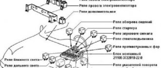
- a siren with a temperature sensor and a hood limit switch in the car engine compartment.
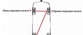
- Connect the antenna unit in the upper corner of the windshield. Place the LED type indicator on the left pillar.
- Attach the shock sensor to the steering wheel bracket , and place the service button in a hidden but easy to access place.
Installation features
All installation and connection work is divided into two stages . The alarm system control unit is connected to the shock sensor and LED so that it starts working correctly. Since the terminals of the security system contacts are the most labor-intensive and critical part of the work, it is necessary to gradually connect the conductors to the relay of the battery terminal battery.
Note! You also need to carefully connect the conductors to the turn signals, siren, trunk release buttons, brake system limit switch, ignition switch, door limit switch.
Connection points for car alarms on Niva Chevrolet
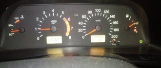
On the 2013 Niva Chevrolet car alarm , the ignition switch is blue and black, the starter is red, the turn signal is blue, blue and red, the handbrake is brown, the tachometer is black.
On the Niva Chevrolet car alarm, the door and trunk limit switches are white or black diode, the turn signal is blue in the driver's threshold. The central lock is blue for opening and brown for closing. Served minus.
Connection points for car alarms on Niva Chevrolet 2017 , all limit switches on the immobilizer unit. The central locking unit cannot be disassembled and soldered in place. Turn - blue and black. Motor control - one positive wire.
Detailed connection instructions
To install an alarm, you need to take electrical tape, a screwdriver, a protective LED, a driver's door activator, a soldering iron, rosin, solder and an alarm. It is important not to start connecting without familiarizing yourself with the theoretical material.
It is worth understanding that the installation methods of signaling may be different. After collecting materials and understanding the introductory information, you can begin to install an alarm :
- Shock sensor connection stage . The sensor must be connected to a three-pin switch connector located on the right side at the bottom of the block housing. Connect the LED indicator connector on the left of the alarm block housing. Connect the button to the contact located at the bottom of the housing alarm unit.
- Central locking . Connect the yellow wire and the yellow wire with a black stripe with a black stripe to the battery that has a positive terminal. Connect the orange wire and the orange wire with a black stripe to the battery with the negative terminal. Connect the remaining white wires to the central ignition switch.
- Connecting an alarm with ten wires of different colors.
We combine two different alarms
So, let's say that one alarm system in the Niva-Chevrolet is already installed (from the factory). This means that we will use the wires connected to its module initially. There are limit switch taps and ground, as well as central locking control wires.
The lock is controlled by two wires - yellow-blue and blue. In addition, you will need to find another cord that powers the passenger door actuators.
The cable we are talking about is a power cable and is usually covered with yellow insulation.
Additional alarm connection diagram
To control all locks, and not just the driver’s actuator, you need to implement the following connection option:
Let's list the features of this option:
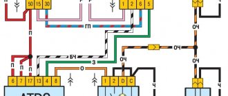
- The relay contacts built into the main unit are connected to the breaks in the signal wires (see figure);
- The normally open contact of the locking relay is left free. In “Shnivy”, closure occurs when the cord is “in the air”;
- The duration of the control pulse is set to “0.8 seconds”;
- The control output is programmed to be activated during unlocking. This output controls another, third relay.
Let's talk about why an additional relay is needed here. If we remove it, we will see that the passenger locks cannot be opened from the key fob. In principle, this option is also acceptable: except for remote unlocking of three doors, everything will work.
The 15 Amp fuse shown in the diagram is in series with the cable leading to the actuators.
Connecting without using a fuse is strictly prohibited. At the same time, it is not necessary to protect the relay windings with a pre-flask. The same applies to the signal wires, that is, to the normally open contact of the unlocking relay. In principle, fuses can be added to all three circuits. And also, the winding of the “lower” relay can be powered from the 87th contact.
Practical implementation of the scheme
Surely the reader knows where the fuse box is installed in the Niva-Chevrolet. This block must be dismantled by unscrewing one screw from the top.
A plastic box will be secured under the indicated block. She is exactly what we need.
There are three “important” cords on the connector of the module shown here: blue, blue-yellow, yellow. Taps from the three break points are extended to the installed signaling, as well as to an additional relay (see diagram). Particular attention should be paid to the connections of power wires.
You can make an additional relay module yourself. A current not exceeding 8 Amperes will flow through the contacts here, so there will be no difficulties:
The diode shown in the main diagram can be anything (its characteristics are not so important). The main thing is that it is there, otherwise you can burn out the control output to which the switched winding is connected.
Remember the main thing: you can carry out any installation work only when the negative terminal is disconnected from the battery.
It is better to connect power cables by twisting, but knowing how to do it correctly is an entire art. All connection points must be isolated. But this will not be enough: in places where the metal touches, the cord is protected with heat-resistant insulation. This is how you can protect yourself from unforeseen consequences.
Connection steps
Step-by-step instruction:
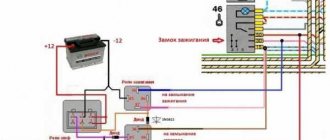
- the topmost yellow conductor to the contacts of the relay power coil. Insert the closed electrical contacts of the relay into the place where the power supply to the ignition coil is interrupted. Cut the cable connecting the relay power coil to the ignition switch. Connect the ends that were formed after the cut to several relay contacts. Then connect the wire that comes from the ignition switch to the wire of the coil relay.
- Connect the black wire It is important to disconnect the battery before connecting to avoid damaging the electrical wiring of the vehicle.
- Connect the brown wires
- Connect the pink conductor Black connect to the housing or to the battery negative pole.
- the red wire to the positive terminal. The yellow and black central locking wires should be connected to it.
- the green conductors or the negatives of the trunk opening to the power coil with an additional relay.
- the white conductor to the ignition switch, the contact that closes when turning the key and the supply voltage, and the blue conductor to the door limit switch.
Note! Connect the orange conductor elements to the brake pedal switch.
Chevrolet Niva Chevy “Panda” › Logbook › Detailed installation of starline a91 on a Chevrolet Niva
And so the installation guide
Starline alarms have many installation maps on the official website for a large number of cars
I’ll explain a little about the manual because... It’s written there superficially And so let’s look at everything, but point by point: 1- remove the steering column casing (unscrew 5 self-tapping screws and 2 screws) according to the instructions photo (1.1-1.3) 2- unscrew the 2 self-tapping panels covering the mounting block (photo 2.1-2.2) and disconnect from the mounting block all the chips. Behind the mounting block there is a standard alarm unit, photo 2.3, disconnect it from the mount (2 nuts under the head for 10) take it out so that it is convenient to work with it)) 3- unscrew the facing panel of the instrument panel together with the instrument panel (6 screws) photo 3.1-3.4
4-install the siren, temperature sensor and limit switch in a place convenient for you) for me these are holes in the frame near the headlight)
Serena's mass and fastening are screwed on with one self-tapping screw
(it is included in the kit) photo 4.1 for the wire to the end switch you will need a terminal (female)
5- install the antenna unit photo 5.1 you will need to remove the left cover on the stand, the LED where you like photo 5.2, and the shock sensor as shown in photo 5.3 Be sure to degrease
6- We don’t attach the alarm unit yet
7-connect the ground limit switches and open and close the cz - ground wire (in my case, the black wire from the X3 block (do not forget to cut the jumper from the black wire - this is the manual transmission mode) on the standard cz unit
closing - we cut it (the blue wire is located next to the blue one with a black stripe) we connect to it from the signaling the wires from X2, the green one to the wire that goes to the central control and the green one with a black stripe from X2 from the end that went to the window motor
Opening - we cut the yellow with a blue stripe on the standard cz photo 7.3, connect it from X2 with a blue one with a black stripe to the cz and the blue one to the end which goes to the motor.
Don’t forget to cut the jumper on the X2 red-black wire
We bite off the door limit switch (white with a blue stripe photo 7.5) on the rear door switch (white with a black stripe photo 7.6) the front right door limit switch (yellow with a black stripe) and connect all these 3 wires to the X3 blue-black wire (door input -) indicated on the diagram
We connect the trunk end switch (white with a red stripe on the cz) to the orange-white X3 (trunk entrance in the diagram)
The hood switch installed earlier is connected to the orange-gray X3 with the gray one coming out under the hood for the siren and connecting to the red one for the siren)
8-connect the turn signals (photo 8.1-8.3) on the red chip of the instrument panel, without breaking it, we tie the green-yellow to the wall and to the blue with a red stripe the green-black from X3 Photo 8.1)
on the white chip there is a parking brake (photo 8.2) without cutting it from the X3 orange-violet,
tachometer photo 8.3 brown with a red stripe without breaking it from X3 gray with a black stripe
9- standard immobilizer bypass module In the gap in the white wire of photo 9 we tie up the gap in the black wire that came complete with the bypass module; we also insert the 2nd ignition key into the module
10 - starter ignition and power To the wires that go to the ignition switch we tie up the wires from block X1 To the ignition wire (blue with a red stripe photo 10.1) we tie up the yellow one from X1 To the starter wire (red thick and thin photo 10.2) we tie up the black and yellow thick one from X1 To the permanent positive wire (brown photo 10.3) we tie the red thick one from X1
Car alarm connection points for Niva Chevrolet 2010
Author Alexander
Driver's door – white/blue Passenger's door – yellow/black Rear doors – white/black trunk – white/red hood – green/black All limit switches are negative
Turns – blue and blue/black
Central locking block behind the mounting block. Central lock (-) – closing – 7th leg, opening – 2nd leg. To control the central locking, you need to solder to the block.
On this car, the first press of the standard key fob opens the driver's door, the second press opens the passenger door. One of the well-known sites has connection points using an additional relay. But I don’t think this method is the best. That's why I offer mine. The central locking unit on the Chevy Niva is from Kalina.
We independently install an alarm system on a Chevrolet Niva: connection points
Every modern car must be equipped with a reliable anti-theft system that will prevent break-ins and theft of the vehicle. Since standard anti-theft installations are not particularly reliable, car owners have to install alarms on their cars themselves. What are the alarm connection points in a Niva Chevrolet car, and how to connect the alarm correctly - find out from this material.
Standard anti-theft system "Shnivy"
Depending on the configuration, the Niva's electrical circuit can be supplemented with a standard alarm system, which, in essence, is a central locking system. If there is a lock, the system is controlled using one module - a block, which represents the signaling system.
The standard anti-theft system is characterized by the following monitoring features:
- it monitors the condition of the internal perimeter of the vehicle body using ultrasound;
- in the same way, the system monitors the safety of the car interior;
- The standard anti-theft installation also protects the hood and luggage compartment of the car from break-ins.
Since this system is standard, it does not have a notification function. That is, unlike a traditional signaling system, a standard anti-theft installation is not equipped with a siren. In other words, its main function is to lock the car doors, but if someone tries to break into the car or steal it, the driver will not know about it.
Photo gallery “Standard signaling”
Basic faults
What malfunctions may occur in the operation of the central locking:
- Failure or incorrect operation of the unit itself. This problem is one of the most costly, because if the module really fails, then it will most likely have to be replaced, and this pleasure is not cheap. If the unit does not work correctly, then the board may require repair, but it is not a fact that resoldering the elements of the microcircuit will solve the problem. If the unit refuses to work, the system may not lock either all or only part of the doors.
- Oxidation of contacts on the unit connector or on the solenoids in the doors. Quite often, oxidation occurs due to the fact that the block is used in conditions of high humidity. If the interior is humid or water gets on the unit for some reason, over time this will lead to its inoperability. Therefore, before making repairs, you need to determine the cause.
- Another problem is that the wires on the locks are broken; for this reason, only one of the doors may not work. Due to the fact that the wires are placed in rubber corrugations between the doors, their constant opening and closing over time can cause the wires to break. Accordingly, to solve the problem you will only need to replace the damaged section of the chain (the author of the video is Sergey Davydov).
Basic malfunctions and problems that you may encounter when connecting yourself
The connection process is quite labor-intensive. A problem may arise with choosing a large variety of models, installing a car alarm system to the central locking system and choosing an installation scheme. When choosing an alarm system, buyers should consider the functional features of the system.
To solve the problem with installing an alarm, it is necessary to determine the connecting points of the security mechanism, starting from the model and location of such an element as the central unit of the system.
The problem of choosing an installation scheme can be solved using original car alarm circuits.
Problems can arise due to careless or incorrect installation of the control alarm unit , installation of inappropriate security system firmware, incorrect placement of the shock sensor, poor-quality connection to the car wiring, incorrect placement of the key chip during autostart.
Due to poor installation, after some time, twisted or poorly insulated wires will begin to oxidize , which will lead to a break in the electrical circuit. Not only the security system, but also the electrical wiring system of the car will fail. If the alarm is set incorrectly, this will lead to frequent false alarms, which will interfere with the operation of the siren.
Alarm Installation Instructions
Since the standard anti-theft system is not a particularly reliable option, our compatriots often install an alarm system, which, unlike a lock, can more effectively protect the car. Before installing the alarm, you must carefully study the diagram that comes with the kit, as well as the instructions. The easiest way to connect an alarm system: we look up Starline alarm connection points on the Internet (the alarm systems are almost identical in connection), find the colors of the wires, the location, and in general we make it easier for ourselves to connect the necessary wires.
Briefly about alarm installation:
- First, in Niva, you need to dismantle the steering column trim; to do this, you will need to unscrew five self-tapping screws and two bolts.
- Now you will need to gain access to the control device - the block; to do this, you need to unscrew two screws on the panel that cover the device, and one screw that secures the module. The device is dismantled, all wires must be disconnected from it.
- Then the dashboard is dismantled. To do this, unscrew four self-tapping screws, two of them located under the plugs. The device itself will need to be removed.
- Now we directly install the components of the new anti-theft system. To do this, first install the sirens, temperature controller, and hood switch in the engine compartment. The temperature sensor should be installed in close proximity to the engine - this way it will transmit the most accurate data (of course, if this controller is included). And the siren must be placed so that it is not affected by moisture and high temperatures, with the horn facing down.
- The next step is to install the antenna adapter - it is placed behind the dashboard or at the top of the windshield. The LED indicator should also be mounted in the antenna area or on the left pillar of the car. As for the shock sensor, it is best to install it on the steering shaft bracket. Also at this stage, the installation of a service button is carried out - it is advisable to install it in a convenient, but inaccessible place for the criminal.
- Next, the signaling control module is installed in the dashboard area.
- After this, all you have to do is connect the wires and configure the shock sensor so that it does not trigger unnecessarily. The wiring is connected in accordance with the diagram that comes with the kit.
Remote control system for electrical accessories Niva Chevrolet
Page 1 of 2
- ignition key;
— door lock key;
— working key of the APS-6 immobilizer;
— remote control for electrical accessories.
To operate the remote control as part of the SDUEP, it must be trained using the training key for the immobilizer (see “Training the immobilizer”). After training, the remote control is also a working immobilizer key and is used to remove the engine start ban.
Connection to CAN and LIN buses is made in accordance with the connector diagram
For correct operation of CAN and LIN buses, you should familiarize yourself with how the operation of these interfaces is organized in your car. If your car does not support control of central locking and light signals via the CAN bus, you should use the following connection diagram.
The Starline A93 security complex provides four ways to control the central lock:
- low current control;
- force positive control;
- force negative control;
- two-wire control.
The connection diagram for low-current control is shown in the figure.
Power control connection diagram
The StarLine A93 system provides various engine blocking options. The most common option is shown in the figure
The preferred blocking is usually blocking the voltages supplied to the injectors and the fuel pump power circuit. This blockage stops the supply of fuel to the engine, thereby making it impossible to start the engine. At the same time, a power failure of these devices does not lead to the accumulation of engine errors, as when, for example, the ignition coil is blocked in gasoline engines.
Therefore, Starline A93 provides additional low-current blocking channels. In using additional locks, you can show originality by blocking some sensor, without which the engine will not start, or the automatic gearbox drive, in order to complicate the transportation of the car.
The electrical package control unit is located in an accessible location immediately behind the fuse box on the left side of the pedal assembly. It can be accessed from below or after partially dismantling the fuse box.
The mounting block with relay and fuse is located under the hinged cover to the left of the steering column. Fuse number F10, the relay position is marked in the diagram with an icon.
Installing a car alarm on a Chevrolet Niva - Connection points, location and colors of wires
Alarm installation
Now all doors will be controlled only by the alarm. The very idea of diode isolation is obvious, but thanks to comrade cht for the connection points. The device is dismantled, all wires must be disconnected from it.
Niva Chevrolet g.v. without standard alarm, only central locking. Tell me the connection points for the central locking and door limit switches. ...
Fuel pump - the fuel pump is controlled by the plus through a thick gray wire. Barnaul, Altai Territory Added: Starter cranking duration - 3.6 seconds.
If the interior is humid or water gets on the unit for some reason, over time this will lead to its inoperability. To do this, first install the sirens, temperature controller, and hood switch in the engine compartment.
Before installing the alarm, you must carefully study the diagram that comes with the kit, as well as the instructions. The easiest way to connect an alarm: Briefly about installing an alarm: First, in Niva, you need to dismantle the steering column trim; to do this, you will need to unscrew five self-tapping screws and two bolts. Now you will need to gain access to the control device - the block; to do this, you need to unscrew two screws on the panel that cover the device, and one screw that secures the module.
The device is dismantled, all wires must be disconnected from it. Then the dashboard is dismantled. To do this, unscrew four self-tapping screws, two of them located under the plugs.
The device itself will need to be removed. Now we directly install the components of the new anti-theft system.
To do this, first install the sirens, temperature controller, and hood switch in the engine compartment. The temperature sensor should be installed in close proximity to the engine - this way it will transmit the most accurate data, of course, if this controller is included.
And the siren must be placed so that it is not affected by moisture and high temperatures, with the horn facing down. I hung it with a plastic strap to the incoming heater hose under the glove compartment. All the same, there is no heater tap on the hose and the temperature of this hose is equal to the engine coolant temperature. At the tidy connector we connect the gray-black wire for monitoring engine operation to the tachometer wire.
Car alarm connection points for Chevrolet Niva 2013
We connect the orange-violet handbrake control wire to the handbrake wire on the tidy connector. We buy any immobilizer bypass module and a key blank with a chip. We register the key in the standard APS system. We put the key into the crawler.
We connect the lineman's control input to the pink alarm wire. We connect the immobilizer crawler output to the gap in the white wire of the standard immobilizer frame.
Photo report on the installation of fog lights on Niva Chevrolet
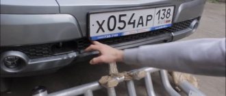
Inserting headlights - unscrew the self-tapping screws of the fender liner (bottom and slightly above), pull them off, unscrew the covers, prepare the headlights. By the way, they are exactly the same as the 2170 (Prior).
We look under the hood in the wiring area at ordinary headlights - the connectors are wrapped with adhesive tape, unwind them and pass them down through the technological holes. We connect the headlights and screw them into place of the previously removed plugs. We screw on the fender liners.
It is important not to confuse left and right. They are marked on PTF glasses.
Connection. On the fuse block there is a connector for the relay, it is empty, it comes with power wires PINK (+ always) and YELLOW-BLUE (- PTF on), and control wires BLACK (ground) and GRAY-BLACK (control +). We insert the relay.
Control button. Remove the front panel of the dashboard (screws near the dashboard and under the plugs near the emergency lights and on the right). There should be a connector not connected - this is the connector for connecting the PTF. We connect the button and voila!
However, if you want the PTFs to work in DRL mode, but turn off when the ignition is turned off, cut off the BROWN wire from the button and connect it to the YELLOW-BLUE wire that goes to the button for turning on the heated rear window.
Comments and reviews
Or we put the ring included in the lineman’s kit onto the lock and connect it with a standard connector. We connect the thick yellow signal wire to the ignition wire from the lock.
We break both starter wires under the lock. We connect the thin black and yellow signal wire from the side of the lock. Thick black and yellow - further into the bundle. We break the black wire of the ground ring in accordance with the choice of manual transmission. We make settings in the signaling: Duration of cranking by the starter - 3.6 seconds.
Engine control - tachometer. Specifically for the shnivy, you can also set the engine type to diesel with a starter delay of 6 seconds.