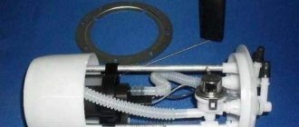
Operating principle
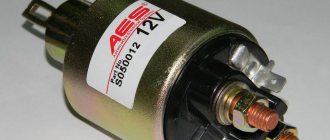
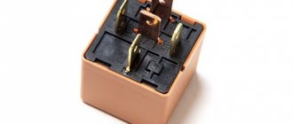
The VAZ 2114 ignition relay is structurally similar in design to other electronic relays.
Its main purpose is to start the starter and, as a result, initiate the start of the engine itself. At the same time, the relay is responsible for other equally important tasks, for example, for protecting the starter from too high voltage or, on the contrary, for starting the engine when the battery is dead (thus, it corrects the voltage in the power circuit going to the starter) .
In addition, by breaking the electrical circuit after starting the engine, the main relay thereby protects the ignition switch contacts from burning or even melting. Location of the ignition relay for VAZ 2114.
Ignition relay VAZ 2109
Like the starter solenoid relay, the ignition relay serves to remotely activate the starter motor and engage the bendix with the flywheel ring.
The relay operates on the basis of an electromagnet, where a coil is wound around a core.
Design and operating principle
When an electric current passes through the coil, an electromagnetic field is created, under the influence of which the armature moves inside the core. When the power is cut off, the field disappears and the armature begins to move freely along the core.
The ignition relay includes the following components:
- Electromagnet;
- Anchor;
- Return spring;
- Contacts;
- A pair of windings.
The electromagnet, in turn, includes two coils in its design.
Coil type
Peculiarities
It is connected to the ignition relay housing, as well as the control output
The retractor coil is connected to the motor contact as well as the control terminal
Device location
The operating principle of the node is based on the following:
- When voltage is applied to the control contact, electric current begins to flow through the coils. This leads to the appearance of an electromagnetic field, under the influence of which the armature moves, compressing the return spring;
- The armature also moves the bendix, then the rod, which closes the contacts connecting the battery with the starter motor;
- When the contacts are closed, a plus is supplied at the output of the retractor coil, which moves to the motor output. So the current stops passing through it - the magnetic field disappears, but the armature remains in the retracted position due to the influence of the magnetic field from the holding coil;
- The armature returns to its original position after the engine is started and the power is turned off, which occurs under the action of the return spring;
- In this case, the contacts open, the bendix is disengaged;
- The contacts of the retractor relay are bolts that are installed in the textolite cover, as well as plates (can be round or rectangular). They close the bolts when the armature moves.
Check and replacement
If the car shows signs of malfunction, there are signs of breakdown of elements of the ignition system, do not rush to immediately blame the starter or module for everything. Often the culprit may be an element that is insignificant in size and cost - the relay.
Dismantling works
To check the relay you need:
- Arm yourself with an ohmmeter or a multimeter more suitable for a motorist, which has all the necessary modes;
- Check resistance indicators;
- We check the holding coil by connecting one terminal of the tester to the relay connection terminal, and the second to ground, that is, the housing;
- Next, the pull-in winding is checked. Here the terminals are connected to the starter motor field winding connection bolt and the control wire connection bolt;
- If there is no resistance, there is only one output - failure.
Checking with a multimeter
Repairing the ignition switch does not make any sense. The element can only be replaced. Plus, it costs pennies.
Signs of a relay malfunction
Sure signs that the relay has failed may include:
- interruptions in the operation of the stove fan;
- problems with turning on the windshield wipers and heated windows;
- failures to start the engine.
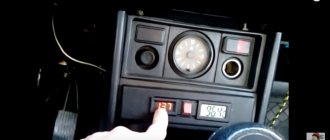
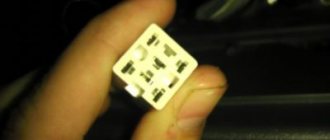
All these factors, and especially their combination, directly indicate that the device is broken and should be replaced. But before you begin the repair, you should find out where the ignition relay is located on the VAZ 2114? You should look for this electronic element under the decorative trim-casing, to the left of the steering wheel. In order to gain access to the relay, this casing must be removed.
In some cases, you can try to remove the relay without removing the casing. This can be done by carefully placing your hand underneath the casing. True, this method requires a certain skill and an accurate understanding of the location and method of attaching the relay. For this reason, when replacing the device for the first time, it is recommended to dismantle the casing.
Ignition relay VAZ 2114 under a protective casing Another, although less rare, but still common problem is overheating of the ignition relay. So, if after a long trip (during which many consumers were turned on, the operation of which is controlled by this relay - windshield wipers, glass heaters) it became very hot, then you should immediately begin searching for the cause, without waiting for the device to burn out or other problems in the on-board network.
As a rule, the high heating of the main relay is due to its low amperage in combination with a large number of consumers (the standard model 14 ignition relay is designed for a current of 70 Amps). In order to check this, it is enough to disconnect a number of devices from the relay (with the exception of the starter, of course) and check its condition after the trip.
If the relay remains cold, then the reason for overheating lies precisely in its low power. To solve this problem, you should install a new relay of a similar design, but designed for a higher current.
Starter relay on VAZ 2114: self-diagnosis of failure
Connection diagram
It is not difficult to determine from the photo where the starter switch is located on the fourteenth VAZ model. This element is located directly on the starter and has two wires:
- The first is red and thin, a small current from the ignition switch passes through it;
- The second thick positive one comes from the battery.
How it works
The device works as follows:
- The battery supplies power to the starter coil;
- The coil acts on the armature due to the influence of the magnetic floor;
- The armature moves and compresses the return spring;
- This causes the bendix to mate with the splines located on the flywheel;
- When the contact elements close, the pull-in winding is deprived of power, and the armature is held inside the system due to the magnetic field;
- After closing the contacts and starting the engine, power stops going to the holder coil, and the armature returns to its place due to the action of the spring. As a result, the bendix disengages.
Malfunctions and their symptoms
Troubleshooting
But it is not at all necessary to disassemble the assembly in order to recognize the signs of a faulty solenoid relay. They look like this:
- The engine runs, but the starter still turns. At the same time, the sound is too loud and uncharacteristic;
- When the ignition is turned on, the starter does not spin, although the relay makes a characteristic click;
- The ignition is turned on, but the starter is idling and the engine does not respond.
All this suggests that there is a high probability of your transmission on the VAZ 2114 breaking. Therefore, it must be removed and a new element installed in place of the damaged one.
Dismantling and replacement
To make it more convenient to replace the relay, it is recommended not to be lazy and still remove the starter itself. This will allow you to simultaneously check the condition of the starter while replacing the relay.
The removal procedure described below concerns an assembled relay, which has the ability to replace individual structural elements.
- Disconnect the negative terminal from the battery.
- Disconnect the red terminal from the relay. This is a red wire.
- Using an 8 mm wrench, unscrew the nut securing the brush assembly. You will find it behind the relay.
- Remove the contact that this nut held in place.
- Unscrew the fastening of the solenoid relay to ground. We are talking about coupling bolts.
- Next, you need to dismantle the power wire, after which the relay itself is pulled out.
- The fastening nuts are unscrewed from the end part, which allows you to remove the upper part of the relay.
- It is advisable to immediately replace the relay core with a new one.
- Install a new relay.
- Proceeding strictly in reverse order, reassemble the assembly, which will allow you to complete the replacement of the unit.
- When separating the relay into its two component parts, be sure to ensure that the core does not slip out and the spring does not jump out.
We can say that replacing the gearbox on a VAZ 2114 is not so difficult. It is much easier to replace a non-separable relay, since to replace it it is enough to unscrew all the fasteners in the same way and disconnect the contacts.
Checking work
Sometimes, despite more than obvious signs of breakage or wear of the retractor, in reality everything turns out to be wrong. The car may behave similarly with some other malfunctions.
Therefore, in order to figure out whether the relay works or not, and also who is the real culprit for the violation of the functionality of the system, we will conduct several checks.
- Check the starter. Turn the ignition key. The starter should begin to turn, and the relay should make a characteristic click. If the starter is not doing its job, replace it. Relyukha has nothing to do with it in this case.
- Check the solenoid relay. To do this, there are two copper bolts on the back cover. Two contacts are attached to them. If the starter starts turning, then your relay has definitely failed and needs to be replaced. In this case, you should not remove the starter, which will allow you to get more accurate test results.
- If you have removed the starter, the check is performed slightly differently : Connect the contact wire of the retractor relay to the positive terminal of the battery;
- The second contact connects the starter ground and the battery charger;
- When the contacts are placed on the relay terminals, the relay should turn on with a characteristic click;
- If the operation is too slow, uncharacteristic, check the condition of the contacts. They often burn out or oxidize.
Differences between starter and relay failure
In order not to confuse what exactly has failed - the starter or the solenoid relay, there is an excellent method for recognizing the “culprit”.
- Remove the starter, connect the negative terminal of the battery to ground;
- The design of the device has copper bolts and a tongue-shaped element;
- The positive wire from the battery is connected to this “tongue”;
- If there is contact, the solenoid relay clicks and starts working;
- If not, then you will have to go to the store for a new relay.
But there is one more very important point. Even if all the facts indicate that the starter or retractor relay is not working, another unit - the ignition switch - may still be the cause of ignition problems. Take the time to check its serviceability before buying new parts.
Price issue
Purchasing a new solenoid relay for a VAZ 2114 is not such a big financial loss. Depending on the region and the store where you purchase the spare part, price tags can range from 300-600 rubles.
How to change the ignition relay
Since the ignition relay is an absolutely irreparable device, the only option for eliminating problems with it is replacement. In order to replace the failed main relay of a VAZ 2114 with a new one (necessarily of a similar model), you will need the following set of tools:
- key to 10;
- crosshead screwdriver;
- slotted screwdriver with a thin narrow blade.
The relay replacement itself is performed in the following order:
- Disconnect the negative terminal from the battery.
- Unscrew the screws securing the protective cover of the steering column.
- Remove the casing.
- Carefully disconnect the old relay from the block with wires.
- Connect the new relay to the block.
- Replace the protective cover and secure it.
Ignition relay in the electrical circuit.
It is worth noting that in some cases the installation location of the ignition relay may differ slightly. Sometimes, in order to get to this part, it may be necessary to dismantle not only the casing, but the entire dashboard.
Sometimes (especially if there is doubt about the relay malfunction and the causes of electronic problems), you can check this device using a multimeter. To do this, the device should be set to ohmmeter mode and one of its probes should be connected to the control output of the relay, and the other to the exciting winding of the starter.
If the relay is working properly, then the device will show the presence of resistance (its specific value is not so important). Otherwise, we can conclude that the relay is guaranteed to be broken and requires replacement. Finishing the conversation about this device, it is worth noting the fact that in some cases an ignition relay just purchased in a store may already be faulty - such things, unfortunately, occur due to manufacturing defects.
That is why, if after replacing the old relay with a new one, problems in the operation of electrical appliances and the engine continue, do not rush to conclusions and look for the cause elsewhere - it is enough to simply check the newly installed relay according to the diagram above.
Published September 22, 2019
Today, every car, regardless of type, is equipped with special protection for all electrical systems. This protection is called a fuse. They are installed so that in the event of a short circuit or malfunction, the system can turn off via a fuse, thereby protecting itself from breakdown.
Fuses are used for every electrical circuit, from a small light bulb to an engine's ignition system. More important engine systems are equipped with special relays, they protect various pumps, electric motors and other powerful sources of electricity consumption.
The fuse is a small structure consisting of a plastic casing with a fusible element inside. If a short circuit occurs, the thin contact melts under the influence of current, which interrupts the electric current. The simplest electrical fuse is a thin copper wire inserted into a circuit.
If the upper limit of the supplied current increases, the contact begins to melt and interrupts the flow of electricity. Here there is a description of all fuses and relays for VAZ 2113, 2114, 2115 models of injection and carburetor types, old and new models.
Step-by-step replacement of the ignition relay
If during the inspection it turns out that the ignition switch relay has failed, then experts do not recommend repairing this element, as was previously said. To buy a new relay, minimal cash costs will be required, and every car enthusiast can make a replacement if all operations are carried out in stages:
- The most important thing to do first is to disconnect the battery from the power supply; to do this, simply disconnect the negative terminal from the battery.
- When using a screwdriver, it is best to use a slotted tool. You need to unscrew the 4 fasteners from the steering column casing to simplify the process of removing the “relay”.
- The latch holding the lower part of the casing is most conveniently unscrewed using a Phillips screwdriver.
- The casing, loosened from the fasteners, is carefully removed from its place.
- The ignition relay is connected to wires that are located at the bottom of the block. To replace an element that has become unusable, you simply disconnect the wires from the block and install a new one in place of the old relay.
After this, you need to check the result of your own work by starting the engine of your car. If the fault does not show itself, it means that the replacement process was completed correctly, and the car owner can be proud of his next, albeit small, but still achievement.
After reading this article, everyone should understand that the process of replacing this device is simple and straightforward. And since the “relay” rarely fails, VAZ-2114 owners do not constantly have to perform such an operation. But if difficulties arise when replacing the ignition switch relay, you should never despair, because you can find the answer to any question in a training video on the Internet resource, which you can watch both day and night.
The training video lesson was prepared and conducted by true professionals who thoroughly understand all stages of car repair. Therefore, everyone will be able to obtain additional information on replacing the relay and determine its exact location from the photo. Well, after watching the training video, the replacement process will become even simpler and you can be sure that every car enthusiast can handle this task.
Interpretation of fuses and relays of injection models
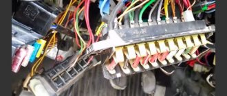
The main fuse module is located under the front engine compartment. This arrangement allows for quick access to all electrical systems of the car.
Location of the block Please note that the location of the electrical fuse module may depend on the type of equipment and year of manufacture of the vehicle. As a rule, this is the upper right part of the engine compartment, under the front windshield. The mounting block is made of plastic in the form of a rectangular box. To protect against accidental opening, the box is equipped with special latches. To open the module, you need to snap off the two protective brackets and lift the top plastic protection. Under the cover are all the main control relays and electrical fuses of the vehicle.
To quickly remove the fuse, special plastic pliers are located on the plastic protection cover. With their help, you can very easily get any element. You need to grab the top edge of the plastic case with pliers and carefully lift the element.
For the convenience of the user, on the top plastic cover there is a complete diagram, made in the form of a schematic image, which shows all the electrical fuses and relays indicating the current strength (A).
Diagram of fuses and relays for injection models Table 1. Explanation of fuses and relays 2114-3722010-60
| Current, A | Explanation of fuses |
| F1 | Rear fog lights, rear fog light indicator lamp |
| F2 | Turn signals and turn signal breaker relay. Alarm system. Hazard warning lamp |
| F3 | Interior and luggage compartment lighting systems (interior lamp, luggage compartment lamp, ignition key illumination). Brake brake lamp, on-board computer backlight lamp. Engine control lamp |
| F4 | Rear window heating control. Portable lamp connection socket |
| F5 | Relay for monitoring and turning on the sound signal. Cooling system engine switch fuse and relay |
| F6 | Control and relay switching on electric windows |
| F7 | Electric motor control - heating system, interior heater, windshield washers, headlight cleaners. Interior cigarette lighter, glove box lamp. Turn on the heated rear window. |
| F8 | Turning on the right fog lamp |
| F9 | Turning on the left fog light |
| F10 | Side light for the left side body, indicator light for turning on the side lights (on the display), lamps for illuminating the license plate and engine compartment, illumination lamp for switches, cigarette lighter, heater control levers. Instrument lighting switch. |
| F11 | Right side body marker light |
| F12 | Front right low beam headlight |
| F13 | Front left low beam headlight |
| F14 | Front left high beam headlight. Light indicator lamp. |
| F15 | Front right high beam lamp. |
| F16 | Body turn signals, relay-breaker for turn signals and hazard warning lights. Control relay and reverse lamps, indicator lamps for the on-board instrument control system, lamps for oil pressure, handbrake activation, brake fluid level, battery charge. On-board computer, engine generator winding. |
| F17-F20 | Spares |
| Relay circuit | |
| K1 | Headlight cleaners |
| K2 | Turn signals and hazard warning lights |
| K3 | Windshield wiper |
| K4 | Monitoring the serviceability of brake light lamps and side lamps |
| K5 | Window lifters |
| K6 | Sound signal |
| K7 | Heated rear window |
| K8 | High beam headlights |
| K9 | Low beam headlights |
Modern fuses vary in color depending on the number of amps.
- 5A – brown
- 10A – red
- 15A – blue
- 20A – yellow
- 30A – green
The color distinction is made for ease of use and identification of the right fuse with the right resistance. There are also fuses available in black, grey, purple, white, orange and other colors. They all differ in the number of amperes that are registered on each product.
In each block, the manufacturer provides additional electrical fuses. They are designed to allow quick replacement of a burnt-out element. They are located at the bottom of the module and are marked with the names F17, F18, F19, F20. Each replacement element differs in color and number of amps.
If one of the electrical appliances in a vehicle breaks down, it is recommended that you first check the mounting block. To determine the burnt element, you need to completely turn off the engine and remove the key from the ignition. Using special pliers, carefully remove the burnt out module.
Hold it up to the light and check for damage to the circuit. It is permissible to use fuses with a higher number of amperes, but only for a short time.
Decoding fuses and relays of block 2114-3722010-18
VAZ-2114, 2115, 2113 cars of the first models with a carburetor have certain differences in the fuse module.
Diagram of fuses and relays of the old-style block Table 2. Decoding of fuses and relays of block 2114-3722010-18
| Current, A | Explanation of fuses |
| F9 | Right rear fog lamp |
| F8 | Left rear fog lamp |
| F1 | Front headlight cleaners at the moment of switching on, wiper contacts, headlight washer switch valve, headlight wiper switch relay contacts |
| F7 | Front headlight wipers during operation, winding of the relay for turning on the wipers, fuse for the interior heater, windshield washer, gearbox and timing controller for the rear window wiper, valves for turning on the front and rear washer, relay (winding) for turning on the engine cooling system, relay for turning on the rear window heating, glove box lighting, rear window heating control lamp |
| F16 | Turn signal indicators and activation of hazard warning lights in turn mode, indicator control lamp, reversing lights, gearbox and relay for activation of windshield washers, generator winding (at startup), control lamps for brake fluid, oil pressure, carburetor flap, hand brake. "STOP" display lamp, voltmeter and coolant temperature indicator |
| F3 | Interior lighting and rear brake light |
| F6 | Power windows, power windows on/off relay |
| F10 | License plate lights, engine compartment lamp, warning light on the dashboard (exterior lighting), instrument panel lights, cigarette lighter light, heating lever lights |
| F5 | Relay for turning on the cooling system fan (electric motor), sound signal. |
| F10 | Left front headlight. Left rear headlight. |
| F11 | Right front headlight. Right rear headlight. |
| F2 | Hazard warning lamp, turn signals and hazard warning relay. |
| F4 | Rear heated glass, heating on, portable socket, cigarette lighter in the cabin |
| F15 | Front right high beam |
| F14 | Front left high beam Light control. |
| F13 | Left low beam |
| F12 | Right low beam |
| Relay circuit | |
| K1 | Headlight washers |
| K2 | Hazard and turn signals |
| K3 | Windshield wipers |
| K4 | Monitoring the health of lamps |
| K5 | Windows |
| K6 | Sound signal |
| K7 | Heated rear window |
| K8 | High beam headlights |
| K9 | Low beam headlights |
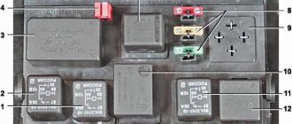
Explanation of the additional fuse and relay block
To turn on the main systems of any car, the manufacturer has designed the installation of auxiliary fuses. As a rule, they are located in the center console area. Each auxiliary module consists of several important relays and fuses.
In this particular case, the box is located to the left of the glove compartment, behind the side trim of the center console. To quickly access the box, you need to remove part of the plastic protection. The protection is attached to Phillips bolts, so you need to prepare the appropriate screwdriver.
Location of additional fuse and relay box 2114, 2115, 2113.
Additional unit in the cabin.
Diagram of the additional block Table 3. Decoding of the additional fuse and relay block
| Current, A | Purpose (Fuses) |
| Main distribution relay | |
| Controller power | |
| Fuel pump | |
| Purpose (Relay) | |
| K4 | Fuel pump |
| K5 | Cooling fan |
| K6 | Main system control relay |
There are also options for other decryptions.
None 1 — fuel pump;
2 - main thing; 3 - fans.
Fuse: f1 - fuel pump;
f2 - main relay; f3 - ECU (electronic control unit).
Relays that control the supply of current are present in the design of many vehicles. They are designed to perform a very important function - they turn on and off important electrical devices and mechanical systems of the vehicle. In simple terms, this is a device for supplying current to a required element.
Starter, ignition, rear fog lamp relay
In order to carry out quick checks and repairs, the ignition system relay is installed under the front dashboard of the car, behind the hood release handle. It is located just below the central dashboard. The module is closed with a plastic plug, which must be opened slightly to test for functionality.
None The main task of the relay when igniting is to reduce the applied load to the contacts. When the engine starts, the relay turns off some electrical circuits in the vehicle system. The system is used not only in injection, but also in carburetor engines.
In the event of a malfunction or malfunction in the ignition system, it is necessary to monitor the operation of the relay. For this purpose, open the box and carefully remove the desired element. It is attached using contacts to special grooves. The first thing to do is look at the oxidation of the contacts, if necessary, clean them with a soft cloth or treat them with a special liquid.
To check functionality, you need to use a regular multimeter. We connect to incoming connections and check the numbers. If there is no short circuit when current is applied, it means the element is not working.
Replacement is carried out in a similar manner. It is necessary to use a standard element with the number of amperes indicated on the housing.
Starter relay VAZ 2109 principle and features of its operation Video AvtoNovator
The VAZ 2109 starter retractor relay is responsible for inputting and outputting the starter from the state of engagement with the car engine. This small and simple mechanism is of great importance for the normal operation of the internal combustion engine.
Design and principle of operation of the VAZ 2109 starter relay
The operation of the relay is based on electromagnetism: a copper conductor is wound around the tubular core of the device, and when current passes through this structure, a magnetic field is created. Under the influence of the resulting force field, the anchor located in the tube is pulled inward.
The design of the described device has two coils.
The switching on of the first is noted at the moment when voltage is applied to the relay, the second begins to work after the armature enters the core.
The anchor overrunning clutch is connected by a lever directly to the anchor. Due to this relay, firstly, it controls the process of supplying voltage to the internal combustion engine, and secondly, it allows the gear to engage with the flywheel of the car engine.
The additional VAZ 2109 starter relay has several contact pins. Two of them transmit current from the car battery, and one has the status of a controller (a wire runs from it to the vehicle’s ignition switch), which controls the operation of the entire device. The control terminal is the thinnest, and the power contacts look like bolts of relatively large thickness (they are mounted on a textolite cover). Inside the relay, the contacts are rectangular or round.
As you can see, the design of the relay is quite simple; any car enthusiast can figure it out after spending very little time. The task of this machine unit is to transmit torque to the starter flywheel by turning off the power and disconnecting the wire after starting the vehicle engine.
https://youtube.com/watch?v=Ao7NsU_Kh2E
For what reasons can the starter relay fail?
Most often, failure of this device is caused by burning of its contacts. The phenomenon is very common, due to the fact that a high current flows through the relay (from 80 to 300 A). Because of this, a spark gap may form, which causes the contacts to burn. This in turn leads to low conductivity of electrical energy.
Also, a break in the winding is often noted on the solenoid relay. In cases where such a disaster occurs in the middle of the winding, the driver has no choice but to buy and install a new device. But when a break occurs in the soldering area of the winding and contact, the situation can be corrected by replacing the damaged area.
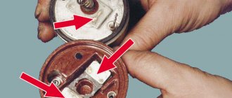
How to repair the retractor?
To carry out repairs, the car enthusiast will need to disassemble the mechanism, guided by the following diagram:
- first remove the nut holding the wire connecting the lower contact of the retractor with the starter winding;
- then the housing is disconnected from the starter (this is easy to do using a regular screwdriver).
The back cover is screwed to the relay body. It needs to be removed (unscrew the bolt) in order to be able to clean the contacts using a needle file. This solves the problem of soot formation.
After disassembling and repairing the mechanism, it is recommended (as they say, “in passing”) to check it for a break or short circuit. To do this, connect an ohmmeter between the bolt that sends voltage to the starter and the control contact (checking the winding) or between the housing and the control contact (checking the coil). If there are no faults, the device should show the following values:
- 0.75 Ohm for holding coil;
- approximately 0.55 Ohm for the pull-in winding.
Front fog lamp relay
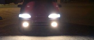
Front fog lights are not standard equipment on the model and are equipped depending on the configuration. The relay itself (if there are fog lights) is located in the engine compartment on the left mudguard.
Front fog lamp relay.
Important! To access the relay, you must remove the battery! Without performing this manipulation, it will be difficult to remove and check its functionality.
Replacing a faulty element is very simple. You need to take a Phillips screwdriver (with a short handle), unscrew the bolt securing the relay to the car body, and check the element for malfunction. If it fails, we buy a new one and put everything in the reverse order.
The location of fuses and relays in the blocks may differ depending on the year of manufacture and vehicle configuration
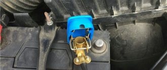
The main part of the fuses and relays is located in the mounting block of the engine compartment. To get to it you need to press two latches and remove the cover.
We take out the fuses with pliers; they are located in the block.
On the inside of the cover there is a diagram of the location of the relays and fuses.
Mounting fuse block 2114-3722010-60 Explanation:
| Relay/fuse no. | Decoding |
| K1 | Headlight wiper relay |
| K2 | Relay-breaker for direction indicators and hazard warning lights |
| K3 | Windshield wiper relay |
| K4 | Relay for monitoring the health of brake lamps and side lights |
| K5 | Power window relay |
| K6 | Horn relay |
| K7 | Heated rear window relay |
| K8 | High beam relay |
| K9 | Low beam relay |
| F1-F16 | Fuses |
| F1-F20 | Spare fuses |
| Fuse no. | Protected Circuits |
| F1 (10 A) | Fuse for fog lights VAZ 2114, 2115 - rear fog light lamps and rear fog light indicator lamp |
| F2 (10 A) | Direction indicators, relay-interrupter of direction indicators and hazard warning lights (in hazard warning mode) Hazard warning lamp |
| F3 (7.5 A) | Front interior lamp. Central interior lamp. Luggage compartment lighting. Illumination lamp for the ignition switch. Lamp for monitoring the engine management system. Brake light bulbs. Trip computer (if installed) |
| F4 (20 A) | Socket for connecting a portable lamp. Relay for turning on the heated rear window (contacts). Rear window heating element |
| F5 (20 A) | Sound signal. Horn relay. Cooling fan electric motor. Fan fuse. |
| F6 (30 A) | Electric windows. Power window relay (contacts) |
| F7 (30 A) | Heater electric motor. Heater fuse for VAZ 2114, VAZ 2115. Electric motor for windshield washer. Headlight wiper motors (in operating mode) Cigarette lighter fuse. Glove box lighting lamp. Rear window heating relay (winding) |
| F8 (7.5 A) | Fuse for fog lamps VAZ 2114, 2115 - Right fog lamp |
| F9 (7.5 A) | Fuse for fog lamps VAZ 2114, 2115 - Left fog lamp |
| F10 (7.5 A) | Side light lamps on the left side. Indicator lamp for turning on the side light. License plate lamps. Engine compartment lamp Instrument lighting switch. Fuse for backlight lamps of switches, instruments, cigarette lighter, ashtray, heater control levers |
| F11 (7.5 A) | Side light lamps on starboard side |
| F12 (7.5 A) | Right headlight (low beam) |
| F13 (7.5 A) | Left headlight (low beam) |
| F14 (7.5 A) | Left headlight (high beam). High beam indicator lamp |
| F15 (7.5 A) | Right headlight (high beam) |
| F16 (15 A) | Direction indicators, relay-interrupter for direction indicators and hazard warning lights (in turn indication mode). Reversing lamps. Relay for monitoring the health of lamps. On-board control system display unit. Instrument cluster. Insufficient oil pressure indicator lamp. Parking brake indicator lamp (brake light fuse). Brake fluid level indicator lamp. Low battery indicator lamp. Trip computer (if installed). Generator field winding (in engine starting mode) |
Mounting fuse block 2114-3722010-18 Explanation:
| Relay/fuse no. | Decoding |
| K1 | Headlight wiper relay |
| K2 | Relay-breaker for direction indicators and hazard warning lights |
| K3 | Windshield wiper relay |
| K4 | Lamp health monitoring relay |
| K5 | Power window relay |
| K6 | Horn relay |
| K7 | Heated rear window relay |
| K8 | High beam relay |
| K9 | Low beam relay |
| F1-F16 | Fuses |
| Fuse no. | Decoding |
| F9 (7.5 A) | Right fog lamp |
| F8 (7.5 A) | Left fog lamp |
| F1 (10 A) | Headlight cleaners (at the moment of switching on). Relay for turning on headlight cleaners (contacts). Headlight washer activation valve. |
| F7 (30 A) | Headlight cleaners (in operating mode). Relay for turning on headlight cleaners (winding). Heater fan electric motor - heater fuse. Window washer motor. Rear window wiper motor. Rear window washer timing relay. Valves for turning on the windshield and rear windows. Relay (winding) for turning on the electric fan of the engine cooling system. Relay (coil) for turning on the heated rear window. Rear window heating indicator lamp. Glove box lighting lamp. |
| F16 (15 A) | Direction indicators and relay-interrupter for direction indicators and hazard warning lights (in turn indication mode). Turn signal indicator lamp. Rear lights (reversing lamps). Gearmotor and windshield wiper activation relay. Generator excitation winding (when starting the engine). Brake fluid level warning lamp. Oil pressure warning lamp. Carburetor air damper warning lamp. Parking brake warning lamp. "STOP" light display lamp. Coolant temperature gauge. Fuel level indicator with reserve warning lamp. Voltmeter. |
| F3 (10 A) | Rear lights (brake lamps). Interior lighting |
| F6 (30 A) | Power windows for front doors. Power window relay |
| F10 (7.5 A) | License plate lights. Engine compartment lamp. Instrument lighting lamps. Indicator lamp for external lighting. Heater lever illumination display. Cigarette lighter lamp. |
| F5 (20 A) | The electric motor of the engine cooling system fan, and its activation relay (contacts). Sound signal and relay for its activation. |
| F10 (7.5 A) | Left headlight (side light). Left rear light (side light). |
| F11 (7.5 A) | Right headlight (side marker). Right rear light (side light). |
| F2 (10 A) | Direction indicators and hazard warning relay-breaker (in hazard warning mode). Hazard warning lamp. |
| F4 (20 A) | Rear window heating element. Relay (contacts) for turning on the heated rear window. Plug socket for portable lamp. Cigarette lighter. |
| F15 (7.5 A) | Right headlight (high beam) |
| F14 (7.5) | Left headlight (high beam). Indicator lamp for turning on the high beam headlights. |
| F13 (7.5 A) | Left headlight (low beam) |
| F12 (7.5 A) | Right headlight (low beam) |
Fuse diagram for VAZ 2114, 2115 Explanation of the diagram (the outer number in the designation of the wire tip is the number of the block, the inner number is the conventional number of the tip):
| Relay/fuse no. | Decoding |
| K1 | Headlight wiper relay |
| K2 | Relay-breaker for direction indicators and hazard warning lights |
| K3 | Windshield wiper relay |
| K4 | Lamp health monitoring relay |
| K5 | Power window relay (in vehicle version) |
| K6 | Horn relay |
| K7 | Heated rear window relay |
| K8 | High beam relay |
| K9 | Low beam relay |
| F1-F16 | Fuses |
Removing the mounting block VAZ 2113, 2114, 2115 First, you need to disconnect the negative terminal of the wire from the battery. Afterwards, in the cabin (under the dashboard on the left), you need to disconnect the five blocks of the wiring harnesses at the bottom of the block. Then remove the cover of the mounting block.
Disconnect the wiring harness block at the top side of the block. Using a 10mm socket with an extension, unscrew the nut of the left fastening of the mounting block.
We disconnect four more harness blocks at the bottom of the block.
Now you can remove the mounting block. You can install by following the reverse steps.
Fuse box for VAZ 2114, VAZ 2115 in the passenger compartment.
This block is located in the lower left part under the glove compartment on the center console. This block may differ in different modifications of the car. VAZ 2114 and VAZ 2115 may also differ
1 - fuel pump relay2 - main relay3 - fan relay f1 - fuel pump fuse VAZ 2114, VAZ 2115f2 - main relay circuit fuses.
None B - mounting block area located in the engine compartment of the car.
Location of block Ш11: Diagram of internal connections of mounting block 2114.
Explanation:
| Block | plug | Color | Electrical circuits |
| Ш1 | BG | Power window control buttons | |
| G | Ignition switch (terminal 15/2) | ||
| MS | Ignition relay | ||
| ZhG | Heater motor switch | ||
| R | Ignition switch (terminal 30) | ||
| KR | Ignition switch (cl. 30/1), ignition relay | ||
| R | Door lock control unit | ||
| P | Ignition switch (terminal 50) | ||
| Ш2 | BG | Rear window wiper switch | |
| G | Turn signal switch (right) | ||
| P | Brake light switch | ||
| BC | Lamp continuity warning lamp | ||
| IF | Hazard switch | ||
| GB | Left front door | ||
| Reserve | |||
| AF | High beam warning lamp | ||
| Reserve | |||
| VERY | Rear fog light switch | ||
| GP | Fuel reserve warning lamp | ||
| IF | Fuel level warning lamp | ||
| Warhead | Interior lighting | ||
| KG | Handbrake warning lamp | ||
| MS | Turn signal switch (left) | ||
| Reserve | |||
| H | Weight " - " | ||
| Ш3 | AND | Speed sensor | |
| Emergency | Hazard switch | ||
| GK | Turn signal switch | ||
| SB | Oil level warning lamp | ||
| H | Weight | ||
| RB | Washer fluid level warning lamp | ||
| RF | Brake lining wear warning lamp | ||
| Z | Exterior light switch | ||
| ZhZ | Windshield wiper and washer switch | ||
| PG | Portable lamp connection socket | ||
| reinforced concrete | Windshield wiper and washer switch | ||
| RK | Windshield wiper and washer switch | ||
| ZhP | Outdoor Light Switch | ||
| AND | Fog light warning lamp | ||
| Reserve | |||
| SG | Oil pressure indicator | ||
| Reserve | |||
| R | Windshield wiper and washer switch | ||
| CO | Windshield wiper and washer switch | ||
| WITH | Windshield wiper and washer switch | ||
| Reserve | |||
| Ш4 | Salary | On and indicator lamp for heated rear window | |
| GB | Headlight switch (high beam) | ||
| OG | Windshield wiper, instrument cluster | ||
| ZhP | Exterior light switch, parking light switch | ||
| TO | Instrument lighting rheostat | ||
| Reserve | |||
| BW | Windshield wiper and washer switch | ||
| ABOUT | Terminal Sh4 - 3 | ||
| midrange | Horn switch | ||
| B | Brake light switch | ||
| Reserve | |||
| JV | Headlight switch (low beam) | ||
| ZhP | Steering light switch | ||
| Reserve | |||
| B | Off headlight cleaner | ||
| RG | Brake fluid level warning lamp | ||
| ZB | Coolant temperature gauge | ||
| KB | Battery charge warning lamp | ||
| WITH | Fog light switch | ||
| GO | Coolant level warning lamp | ||
| KP | Tachometer | ||
| Ш5 | Z | High beam (right) | |
| AF | High beam (left) | ||
| midrange | Low beam (left) | ||
| GP | Starter (cl. 50) | ||
| G | Electric radiator cooling fan | ||
| WITH | Low beam (right) | ||
| Ш6 | Reserve | ||
| Z | Reversing light switch | ||
| MS | Turn signal (left front) | ||
| Reserve | |||
| Reserve | |||
| Reserve | |||
| Z | Headlight cleaner relay, electric relay headlight washer motor | ||
| AND | Side light (right front) | ||
| Warhead | Off engine compartment lamp | ||
| ZhCh | Side light (left front) | ||
| G | Turn signal (right front) | ||
| ABOUT | Reversing light switch | ||
| RG | Brake fluid level sensor | ||
| Ш7 | Reserve | ||
| ZhG | Email f r cleaner engine | ||
| B | Email headlight cleaner motor | ||
| Reserve | |||
| SB | Oil level sensor | ||
| midrange | Sound signals | ||
| WITH | Speed sensor | ||
| ZB | Coolant temperature sensor | ||
| F | Generator (cl. 61) | ||
| Z | BUEM (cl. 5) | ||
| Warhead | Engine compartment lamp switch | ||
| RB | Washer fluid level sensor | ||
| RF | Brake pad wear sensor | ||
| JV | BUEM (cl. 6) | ||
| KP | Ignition coil | ||
| RZ | Coolant level sensor | ||
| midrange | Fog light relay | ||
| Ш8 | ZhP | Fog light relay | |
| ZhCh | Fog lamp (left) | ||
| AND | Fog lamp (right) | ||
| GP | Ignition coil, BUEM (cl. 4) | ||
| R | Generator (cl. 30) | ||
| R | Generator (cl. 30) | ||
| R | Starter relay | ||
| RF | Fog light relay | ||
| Ш9 | Reserve | ||
| G | Turn signal (right rear and side) | ||
| BG | Email rear window wiper motor | ||
| VERY | Rear fog lights | ||
| midrange | Rear door limit switch | ||
| IF | Front right door limit switch | ||
| Warhead | Interior lighting | ||
| KG | Parking brake warning light switch | ||
| MS | Turn signal (left rear and side) | ||
| WITH | Rear window heating elements | ||
| WITH | License plate light | ||
| GB | Front left door | ||
| B | Interior lighting | ||
| P | Brake lights | ||
| AND | Side light (right rear) | ||
| Z | Reversing light | ||
| ZhCh | Side light (left rear) | ||
| ZhG | Rear window wiper | ||
| WITH | Rear window heating element | ||
| Ш11 | RB | Washer pump | |
| RF | Rear window washer valve | ||
| Reserve | |||
| Z | Carburetor limit switch | ||
| Warhead | Engine compartment lamp | ||
| JV | Carburetor electric valve | ||
| Reserve | |||
| TO | Engine compartment lamp | ||
| B | Windshield wiper motor | ||
| ABOUT | Windshield wiper motor | ||
| Reserve | |||
| SG | Emergency oil pressure sensor | ||
| Reserve | |||
| R | Windshield washer valve | ||
| CO | Wiper motor | ||
| WITH | Wiper motor | ||
| Reserve | |||
| reinforced concrete | Wiper motor | ||
| Reserve |
SEE ALSO - fuses and relays for...: