The uninterrupted operation of the power unit depends on the serviceability of each individual element. If a characteristic metallic knock is noticed during its operation, this is usually caused by wear or rotation of the upper/lower sliding element. In this case, replacing the engine liner is carried out quickly in order to protect the engine from major repairs.
How to replace bearings without removing the engine?
To replace the liners successfully, it is not at all necessary to dismantle the motor. If you are assured that it is impossible to get to them without removing and pulling the engine out of the hood, urgently change the car service center. But be sure to take into account one condition - the crankshaft (CV) should not be worn out. Otherwise, you won’t be able to do without removing the engine and completely disassembling it!
Without dismantling the power unit, it is easier to change the connecting rod bearings; it is more difficult to change the main bearings. For the latter case, you need to loosen the fastenings and release the crankshaft by 10-15 cm. Although there is another method, adopted by our grandfathers from ship motorists. The main bearings are pushed out using a soft rivet or bolt, which is inserted into the desired lubrication passage and rotated clockwise. The main thing is that the size of the aluminum insert should be slightly smaller than the hole and not scratch the crankshaft.
After removing the half rings, it is imperative to evaluate their condition. If there are no visible scuffs or damage, you can get by with a simple replacement. However, if it is very worn, polishing the HF is mandatory. Therefore, you will have to remove it from the mounts, and to do this, pull out the motor.
More information about condition assessment:
- pits or pockets - fatigue wear;
- scratches and ingrained dirt - low-quality motor oil;
- worn surface - insufficient amount of lubricant;
- chamfers on the edge - taper of the necks.
Quick disassembly method
Some experts suggest a risky removal option without removing the cover. All operations must be carried out directly with the engine open. This method saves a lot of time, but with little experience it can do more harm than good. After removing the old oil seal, a new part is installed on the shaft. This must be done very carefully so as not to damage the polished glass surface. If the shaft is damaged, the oil seal quickly wears out, a new engine oil leak appears, and all actions will need to be repeated.
Replacement procedure and marking of liners
Below are instructions for independent work. Replacing the engine liner will be faster and easier if you do it consistently.
- Place the car in a repair pit. Remove the power unit protective cover, if present. Place a jack under one of the drive wheels. Be sure to drain the engine oil.
- Remove exhaust pants and other components that interfere with work from below. Also unscrew the suspensions connecting the engine to the gearbox. Loosen the camshaft chain, remove the starter, and on some cars, the beam.
- Remove the oil pan bolts, nuts and studs.
- Rotate the wheel to move the connecting rods to the most convenient position for unscrewing the bolts. They are tightened with a force of approximately 3 kg, so you need to select the appropriate tool (usually a socket of the appropriate size with an extension). After tearing off the pins, you can continue to unscrew them by hand.
- Remove the half rings along with the connecting rod caps by pulling down. Be sure to check the condition of the internal surfaces of the half rings.
- Pull out the main bearings using a pusher - a bolt of a suitable size or rivet.
- Install a new set of half rings, tighten and reassemble everything in reverse order.
For quick installation of half rings, the connecting rod is completely raised up, moved to the side and lowered. Now nothing will interfere with the work, the sliding element can be inserted faster. Then the connecting rod is put in place.
It is important to tighten the fastener bolts tightly so that they do not loosen after the car has been driven for a long time and cause a malfunction, such as spinning. To do this, tightening is carried out at a specific moment:
The connecting rod bearings are marked with numbers directly on the head. After the initial grinding of the HF, bearings with a size of 0.25 mm are installed. After the second - 0.5 mm, and after the third - 0.75 mm. The latest size is 1 cm. There is no point in processing the crankshaft further.
To ensure that replacing the crankshaft liners without removing the crankshaft is successful, it is recommended to entrust the selection of parts to a specialist. It will correctly calculate the size and you won’t have to reinstall the parts again.
Tuning the crankshaft on a VAZ
- Engine Crankshaft
- Flywheel
- VAZ cylinder head
- Sports camshafts
- Sport timing valves
- Cylinder head components
- Belts | Timing gears
- Gaskets | Oil seals
- Intake system
- Throttle valve
- Clubturbo pistons
- TDMK pistons
- Federal Mogul pistons
- Piston rings
- Connecting rods
- Engine mounts
- Inserts for VAZ engines
- ACL earbuds
- Oil catchers
- Oil crankcase
- Oil pump
- Miscellaneous
- Turbo Turbo kit
- Turbochargers
- Turbo manifold
- Bypass valves
- Westgates
- Intercooler for VAZ
- Intercooler kit
- Piping kit (air ducts)
- Turbo parts
- Adapters for installing an oil cooler | sensors
- Straight pipes
- Blocking
- Vacuum booster
- Clubturbo suspension
- Silencers for VAZ
- Innovate
- Filler necks
- Moto kits Turbo
- Adapters for installing sports steering wheels
- Keychains
- Bumpers tuning for VAZ
- Hoses | tubes
- Thermal insulation
- Crankshaft
- Flywheel
- VAZ cylinder head
- Sports camshafts
- Sport timing valves
- Cylinder head components
- Belts | Timing gears
- Gaskets | Oil seals
- Intake system
- Throttle valve
- Clubturbo pistons
- TDMK pistons
- Federal Mogul pistons
- Piston rings
- Connecting rods
- Engine mounts
- Inserts for VAZ engines
- ACL earbuds
- Oil catchers
- Oil crankcase
- Oil pump
- Miscellaneous
You can pay for your purchase in any convenient way:
- VISA, MasterCard (no commission)
- Receipt for payment
- Sberbank Online
We deliver goods throughout Russia and Kazakhstan
We can send your purchase to you by transport company:
- home
- Catalog
- Engine
- Crankshaft
Crankshaft
Replacing the crankshaft is one of the most popular ways to increase engine torque and improve vehicle acceleration dynamics. Installing a VAZ crankshaft with an increased stroke allows you to increase the piston stroke and, accordingly, change the working volume of the cylinder. Torque is the main indicator that affects the acceleration dynamics of a car. Peak power is only needed to achieve maximum speed. Therefore, when comparing engine parameters, the main attention should be paid to torque. Torque can be increased in several ways, such as: increasing engine displacement, turbocharging, nitrous oxide. Increasing engine capacity is the least expensive way, since for this you will need not the most expensive spare parts: VAZ crankshaft, VAZ pistons, piston rings. When increasing the engine volume for better filling of the cylinders, it is advisable to modify the cylinder head channels of the VAZ. The factory casting of the cylinder head has always been of poor quality, so even minor processing of the channel shape and removal of irregularities will have a positive effect on the performance of your engine. Before installation, the crankshaft of the VAZ on a dynamic stand. Also subject to dynamic balancing are the flywheel, pulleys, and clutch basket. This service is provided by Club Turbo.
When is it necessary to replace crankshaft bearings?
The HF engine experiences heavy loads. Just look at the vibration on the axis, which invariably occurs during the operation of the crankshaft. It is clear that the sliding bearings also suffer, because they take the blow first.
- Physical wear is the main reason when an engine liner needs to be replaced. The surfaces of parts wear out, backlash and vibration increase. Naturally, in such conditions the engine is in danger of knocking.
- Rotation is the second reason. More details about this are written below.
Thus, replacement of liners is required in several cases. Problems can be judged by various signs. For example, by the absence or presence of abrasive inside the lubricant. Also, a symptom of half-ring wear is low interference when installing the connecting rod cap.
Regarding factors that lead to wear or turning:
- dirty or too viscous lubricant - impurities and abrasive particles reduce the properties of the lubricant, and in general its cleanliness is one of the key rules of prevention;
- constant overload of the internal combustion engine - you cannot drive for a long time at high speeds, from time to time you need to pause, slowing down to 80-90 km/h;
- incorrect installation of half rings during a previous repair - as a rule, this occurs due to weak tension (insufficient clamping torque), so tightening must be carried out using a torque wrench.
Rotated liners: what does this mean and why do they rotate?
Rotating the engine bearings is a change in their position relative to the crankshaft journal or block. As mentioned above, this is caused by the colossal loads to which the parts are subjected. Shifting the bearings from their place immediately negatively affects the flow of oil. His pressure worsens, starvation begins and the power unit is destroyed. And all because the half rings are equipped with holes that must clearly coincide with the channels for the passage of lubricant.
The main reasons for cranking
There are several known reasons that cause elements to rotate:
- banal wear - the end parts of the sliding bearings wear out (support collars, stops, antennae), which are no longer able to hold the parts in one place;
- weak, incorrect fixation of the covers - the half-rings must be tightened with a certain torque specified in the passport data.
And of course, this arises due to a violation of the design operating conditions of the plain bearings themselves. In other words, due to a large and uneven load. This happens especially often with half rings with weak tension.
Rotating sliding parts can cause big troubles and therefore requires urgent intervention. The most dangerous is the shift of the main bearings. In this case, the power unit will definitely need an expensive overhaul.
It is noteworthy that when the connecting rod half ring rotates, it is simply updated. However, it is wrong to do so - because the resource of the mating connecting rod-pin pair in this case is reduced by almost 70%. Therefore, it is necessary to replace the connecting rod itself, in which a broken lock can often be found. And the most optimal method of repair is considered to be boring the crankshaft and replacing the complete liners, along with the connecting rods.
The final stage
To secure, apply light blows with the handle of a hammer to the bottom of the piston, thereby pushing it into the cylinder. Screw on the second to fifth main bearing caps so as not to create a significant tightening. After this, purchase an odorless sealant from the store and apply a thin layer of it to the surface of the cylinder block in the place where it will come into contact with the first bearing cap.
After this, install a new sealing ring on the crankshaft and, after checking the location of the chain on the crankshaft sprocket, install the oil pump and pan. Also screw the removed cylinder head back into place, because only after this the structure can be completely assembled and the crankshaft considered replaced.
Selection of crankshaft liners
In most cases, the selection is entrusted to a specialist. But after studying the information in detail, you will be able to do this on your own. In addition to the fact that it is necessary to combine spare parts with the car model, the general condition of the vehicle is also taken into account.
Selection of main liners
Some useful recommendations for selecting a new HF when replacing the crankshaft liners:
- it is better to buy basic elements of the same color as the standard ones (used, old);
- Be sure to check the markings directly on the shaft.
A special identification color selection card is issued for main bearings. For example, for a 4-cylinder engine, the markings applied to the BC and the CV assembly are used. If marked C3, then you can install yellow and green elements. More details about the colors in the picture below.
And this is an identification card for 6-cylinder engines.
Selection of connecting rod bearings
And here, if the HF is new, the plain bearings are selected according to the diagram. If the color code is lost, you need to look at the markings on the connecting rod caps.
Below is an identification card for selecting connecting rod half rings for four-cylinder power units.
And this is the color map for 6-cylinder units.
The choice of bearings also depends on the antifriction coating. As a rule, it consists of several layers:
- biometallic with a steel base (1-4 mm) - lead, copper, zinc, tin, silicon and aluminum;
- trimetallic - lead, tin, copper.
Use the correct engine oil that meets all the requirements and approvals of the engine manufacturer. It is also necessary to update the filter promptly to prevent abrasive particles from entering the lubricant. It is also not recommended to overload the engine. All this will extend the service life of the liners by almost 2-3 times.
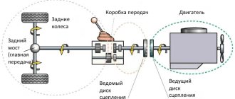
The crankshaft is a key component of the crank mechanism of an internal combustion engine. Thanks to the crankshaft, the reciprocating movements of the pistons are converted into mechanical rotation. The essence of the crankshaft is a crank that performs rotational movements around one fixed axis. Twice the crank radius is equal to the piston stroke length. The connecting rod journals are located at such angles that the cylinders work in pairs, but are slightly ahead of each other. The crankshaft is designed according to this principle.
crank mechanism
Crankshafts are made from high-strength steel or cast iron by casting, forging, and machining. Due to the high compression ratio, higher strength requirements are placed on the diesel engine crankshaft. Otherwise, the diesel crankshaft is no different in structure from the shaft of a gasoline engine. A steel crankshaft, especially one machined, is expensive, which is why cast iron crankshafts have become more widespread.
Manufacturing a crankshaft from steel on a lathe and milling machine
How to install crankshaft cushions correctly
Remember this, the crankshaft cushions cannot be swapped, from which place the cushion was removed, it must be placed there, and the lock on the liner must be placed with the lock of another liner. It’s better to do this: before spinning the crankshaft, fill the pads with core points, the first pad is one dot, the second pad is two dots, etc. I use a set of numbers, but you may not have a set of numbers, then use a core. Also, when you put marks on the pillows, fill them so that you can understand where the front and the back of the pillow are, hit the marks closer to the edge of the front of the pillow, then when assembling, if you are distracted, then by looking at the placed pillow you will understand by the marks that you were not mistaken. VAZ engine mounts have factory marks on the mounts; you don’t have to mark them, but you can mark them and it won’t be any worse.
Photo. The number 2 I stuffed on the second pillow, the top of the number faces in front
I had a case where they asked me to look at the engine, they simply replaced the liners and did not bore the crankshaft. So the crankshaft turned out to be clamped, it immediately surprised me, how can the crankshaft be clamped when they simply replaced the old bearings with new ones.
Everything turned out to be very simple, this master was told by another master that the pillows should not be screwed lock to lock on the inserts, but vice versa. I twisted the pillows as expected, lock to lock, and the crankshaft started spinning. But looking at this crankshaft I immediately realized that all their work was in vain, even at a glance it was full of grooves, I told him that the work would be of no use. But he decided that everything would be fine.
He didn’t drive for a long time; the oil pressure in the engine never appeared, even though he installed new liners.
Crankshaft device
The crankshaft consists of flat machined plates with counterweights (the so-called “cheeks”), which are connected to each other by “necks”. Counterweights are needed to dampen the reciprocating movements of the pistons and stabilize the rotation of the shaft.
Some modern engines use balancer shafts with an offset center of gravity and driven by the crankshaft for additional stabilization. They rotate in different directions, helping to balance the movements of the pistons.
Crank mechanism with an additional block of balancers
In V-twin and W-twin engines, connecting rods from opposing cylinders press against interconnected journals. This allows for more uniform operation of the engine and reduces its dimensions. In in-line engines, each connecting rod is mounted on a separate journal with balancers.
Crank mechanism of an inline four-cylinder engine with standard journals and balancers V6 engine crankshaft with a split adjacent connecting rod journal
The crankshaft journals are cylindrical in shape with a ground surface. The main journals are located along the axis of the shaft, and the “crank journals” are located along the axis of the connecting rods. The rubbing pairs of the crankshaft are usually mounted on plain bearings. To prevent longitudinal displacement of the shaft, support bearings are provided, they are also called crankshaft half rings.
The crankshaft is located in the cylinder block in the reciprocal seats of the “crankshaft bed”. On the crankshaft there is a shank for fastening the timing sprocket, generator pulley and water pump. On the back of the shaft there is a flange for fastening the flywheel. A rolling bearing is installed in the flange, and the gearbox input shaft fits into it. Inside the crankshafts there are channels for forced lubrication of the journal liners, connecting rods and cylinder-piston group. The design of crankshafts depends on the layout of the cylinders and their number. Drive gears for various equipment, such as an oil pump, can be installed on the crankshaft.
Crankshaft device
engine assembly for a VAZ 2110 car | 2111 | 2112
VAZ 2110 engine assembly
Assemble the engine on a VAZ 2110 car as follows. Place a clean cylinder block on the stand and screw the missing studs into the cylinder block. Install the generator mounting bracket and secure it with two bolts. Lubricate the bearing shells and thrust half rings of the crankshaft, as well as the pistons and oil seals with engine oil. When assembling the engine after repair, install new crankshaft oil seals. Install liners with a groove in the 1st, 2nd, 4th and 5th seats of the cylinder block, and liners without a groove in the 3rd seat of the cylinder block and in the main bearing caps. Place the crankshaft in the main bearings and insert the thrust half-rings into the seat of the middle main bearing (Fig. 2-18).
Warning
The half rings must have their grooves facing the thrust surfaces of the crankshaft (an antifriction layer is applied to the surface of the half ring on the side of the grooves).
A cermet half-ring (yellow) is placed on the rear side of the crankshaft middle support, and an aluminum-steel half-ring is placed on the front side. Install the main bearing caps in accordance with the marks on their outer surface (Fig. 2-19).
Unfold the covers so that the marks on each of them are on the side where the generator is installed. Tighten the cover bolts. Check the axial free play of the crankshaft. To do this, turn the cylinder block with its back side up and install a stand with an indicator on it so that the indicator leg rests against the crankshaft flange. Moving the shaft up and down (for example, with screwdrivers), measure the axial free play of the shaft with an indicator (Fig. 2-20).
It should be in the range of 0.06-0.26 mm. If the stroke is greater, then bring it back to normal by replacing the old half-rings with new ones or installing half-rings of increased thickness. Press mandrel 67.7853.9571 into the holder (Fig. 2-21)
rear crankshaft oil seal. Place the holder with the oil seal on the mandrel 67.7853.9572 and move it from the mandrel to the crankshaft flange. Place a gasket under the holder and attach it to the cylinder block with bolts and spring washers. Install the flywheel on the crankshaft so that the mark (cone-shaped hole, shown by the arrow in (Fig. 2-17)
near the rim was located against the axis of the connecting rod journal of the fourth cylinder. Install the flywheel washer and bolts. Lock the flywheel with clamp 67.7820.9526 cm (Fig. 2-17) and tighten the fastening bolts. Apply UG-6 sealant to the flywheel mounting bolts before installation. To ensure that the sealant adheres reliably, degrease the bolts and threaded holes in the crankshaft before applying it. Select pistons to cylinders according to class and assemble the pistons with connecting rods, as indicated in the subsection “Connecting rod and piston group”. Using the adjustable bushing 67.7854.9519, insert the pistons with connecting rods into the cylinders (Fig. 2-22).
Warning
The hole for the pin on the piston is offset from the axis by 1 mm, therefore, when installing the pistons into the cylinders, the arrow on the piston bottom must face towards the camshaft drive.
Install the bearings into the connecting rods and connecting rod caps. Install the connecting rods and caps onto the crankshaft journals and tighten the connecting rod bolts. The connecting rod caps must be installed so that the cylinder number on the cap is opposite the cylinder number on the lower end of the connecting rod. Using mandrel 67.7853.9580, press the crankshaft front oil seal into the oil pump cover. Fill the oil pump with some engine oil and rotate the drive gear several times. Install the oil pump with the crankshaft front oil seal on the mandrel 67.7853.9580 and turn the drive gear to a position so that it can be placed on the crankshaft journal. Move the pump from the mandrel to the shaft, install a gasket under the pump and attach it to the cylinder block. To ensure proper installation of the pump, two guide pins are pressed into its housing (Fig. 2-23),
which must fit into the corresponding holes in the cylinder block. Insert the oil receiver with the O-ring into the hole in the oil pump, attach it to the oil pump and to the cover of the second main bearing of the crankshaft (Fig. 2-16).
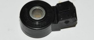
Install oil sump 5 with gasket 4 and secure it. Install the crankshaft position sensor for the fuel injection system on the oil pump cover (if this system is used on a VAZ 2110 car). Install the oil level sensor. Lubricate the oil filter O-ring with engine oil and install the oil filter by hand screwing it to the fitting on the cylinder block. Insert two centering sleeves into the cylinder block (Fig. 2-24)
and install the cylinder head gasket over them. For a correctly installed gasket, the oil passage hole (edged with copper tape) should be in the area of the 5th cylinder head bolt, bolt number (Fig. 2-25).
Warning
When assembling the engine, you must always install a new cylinder head gasket.
Used gaskets are not permitted. Before installing the gasket, it is necessary to remove oil from the mating surfaces of the block and cylinder head. The gasket must be clean and dry. Oil should not come into contact with the surface of the gasket. Rotate the crankshaft so that the pistons are in the middle of the cylinders. Install the cylinder head, assembled in accordance with the instructions in the “Cylinder Head” subsection, using the centering bushings. Tighten the cylinder head bolts in a certain sequence (Fig. 2-25) and in four steps: 1 - tighten the bolts to a torque of 20 Nm (2 kgf-m); 2 - tighten the bolts to a torque of 69.4-85.7 Nm (7.1-8.7 kgf-m); 3 - tighten the bolts 90°; 4 - tighten all the bolts again by 90°;
Warning
The cylinder head bolts may only be reused if they have been extended to a length L of no more than 135.5 mm (Fig. 2-61). If the bolt is longer, replace it with a new one.
Before assembling the engine, lubricate the threads and bolt heads in advance by dipping them in engine oil. Then allow excess oil to drain by letting the bolts sit for at least 30 minutes. Remove oil or coolant from the cylinder head bolt holes in the cylinder block. Insert the coolant pump with the gasket into the cylinder block socket. Install the rear timing belt cover and attach it together with the pump cover to the cylinder block. Additionally, attach the cover with a bolt to the cylinder block and a nut to the stud on the cylinder head. Insert segment keys into the slots at the front ends of the crankshaft and camshaft and install the toothed pulleys. Having blocked the camshaft pulley from turning, secure it with a bolt and washer. Warning
It is prohibited to replace the flywheel mounting bolts with the camshaft pulley mounting bolt and vice versa due to their different coating.
The flywheel mounting bolts are phosphated, and the camshaft pulley mounting bolt is oxidized. Using tool 67.7811.9509, turn the camshaft until the mark on the pulley aligns with the installation lug on the rear cover of the timing belt (Fig. 2-26).
Turn the crankshaft towards a smaller rotation angle until the alignment mark on the pulley aligns with the mark on the oil pump cover (Fig. 2-27).
You can turn the crankshaft with a wrench using a bolt temporarily screwed into the front end of the crankshaft. Install the tension roller with a spacer washer and secure it in a position corresponding to the minimum belt tension. Place the timing belt on the camshaft pulley and, while tensioning both branches of the belt, place the left branch behind the tension roller and put it on the coolant pump pulley. Place the belt on the crankshaft pulley and lightly tension it with the tension roller, turning the roller counterclockwise. When installing the belt, avoid sharp bends. Turn the crankshaft two turns in the direction of rotation and check that the alignment marks (Fig. 2-26) and (Fig. 2-27) match. If the marks do not match, then loosen the belt tension, remove it from the camshaft pulley, turn the pulley to the required angle, put on the belt, slightly tension it with the tension roller, turn the crankshaft two turns again and check that the alignment marks match. If the marks match, adjust the belt tension as described in the “Camshaft and its drive” subsection. Adjust the clearances in the valve mechanism as indicated in the “Cylinder Head” subsection. Install the front timing belt cover and secure it with bolts. Carefully place the gasket into the groove of the cylinder head cover along the entire perimeter. Install the cover on the cylinder head, put the rubber bushings on the studs and attach the nuts and washers. If the bushings show signs of destruction, replace them with new ones. Tighten the nuts evenly in several steps until the washer rests on the stud. Remember that the tightness of the cover depends on the thoroughness of all installation operations. Wrap the spark plugs, coolant temperature gauge and oil pressure warning light sensors into the cylinder head. Install outlet pipe 3 on the cylinder head (Fig. 2-28)
cooling jacket with a gasket and secure it with two nuts. Install the gasket and attach the flange of the inlet pipe 1 of the coolant pump to the cylinder block. Place the hoses leading to the thermostat onto the pipe and supply pipe, install thermostat 2 and secure the hoses with clamps. Install the auxiliary housing with the O-ring on the cylinder head and secure it with a bolt. When installing the housing, pay special attention to the position of the sealing ring in the groove, since when tightening the nuts, it may jump out of the groove and bite between the edges of the groove and the surface of the cylinder head. If the sealing ring shows signs of being bitten, it must be replaced with a new one. In accordance with the instructions in the “Fuel Pump” chapter, install the heat-insulating spacer with gaskets, the pusher and the fuel pump. Install the ignition distributor sensor in the following order. Lubricate with engine oil and place the O-ring on the flange of the ignition distributor. Attach the ignition distributor sensor to the housing of the auxiliary units in such a position that the middle mark on the flange of the distributor sensor is opposite the mounting lug on the housing of the auxiliary units (Fig. 7-21).
At the same time, install the high voltage wire bracket under the upper fastening nut. The ignition sensor-distributor shaft is connected to the camshaft shank in only one position. Therefore, before installation, rotate the shaft so that the cams of the shaft coupling fit into the grooves of the camshaft shank. Place gaskets on the cylinder head studs, install exhaust manifold 1 (Fig. 2-29)
and tighten the central nut securing it. Then install the inlet pipe 3, warm air intake 4, bracket 2 of the coolant pump inlet pipe and secure them with nuts. Install the crankcase exhaust ventilation hose and secure it with clamps to the pipes of the block and cylinder head cover. Install the oil level indicator. Install the right engine mount bracket with mounting plate 3 (Fig. 2-10) of the generator.
Place the generator drive pulley on the crankshaft and secure it with a bolt and washer. Install the generator, put the belt on the crankshaft and generator pulleys and adjust its tension as indicated in the “Generator” subsection. Install the carburetor heat shield, spacer and carburetor. Secure it with nuts and close the top with a technological plug. Warning
Do not fasten (or tighten the nuts) a heated carburetor.
Tightening torque for carburetor mounting nuts “Appendix 1”. Install the gasoline supply hose from the fuel pump to the carburetor and secure it with clamps. Install the hose of the vacuum regulator of the ignition sensor-distributor, as well as the hoses for supplying and discharging fluid from the cooling system to the carburetor. Connect the high voltage wires to the ignition distributor and to the spark plugs. Fix the wire comb in bracket 2 (Fig. 2-9).
Pour season-appropriate oil into the engine through the filler neck on the cylinder head cover.
see also
Comments 27
The procedure for replacing the crankshaft without removing the engine is 99% completely feasible when working by one person. Short-term help is only needed to remove and install the gearbox and carefully install the camshaft. You can easily remove the old distributor by yourself. I installed one, but then I need to lay clean material on the beam and make a hanger for the back of the stake. I installed all the main liners in the block, and prepared 1 and 4 main caps with liners. Then I lubricated everything with oil, first the crankshaft was placed on the beam with counterweights horizontally, it was intercepted, then the rear journal was in the suspension and the front journal was in the seat. Then for a few seconds you need to press the shaft weighing 14.5 kg upward onto the seats with one hand and install 1 main cover in place. Then, without letting go, grab and post the 4th lid. This is the hardest thing. If anyone can help for a minute, the installation will be no problem at all. The advantages of this procedure: - no need to invent a procedure for removing the engine - the cooling system, cylinder head, camshaft, piston, carburetor, distributor, attachments, electrical wiring are also not affected. Even the adjusted ignition will not go astray if you mark the location of the oil pump drive sprocket before loosening the chain.
Cons - oil drips for some time (as already mentioned here), but in insignificant quantities
It’s not the crankshaft that’s knocking... In general, it’s not clear what it is. Replaced: Crankshaft + liners Piston + rings + pins Camshaft with housing + rocker with adjusting bolts Chain, sprockets, shoe, damper Piglet + fungus Compression is a beast, the finger is sucked into the breather tube...
I tried it like in this video, I pump it sharply and there seems to be something knocking in the fourth cylinder. But you can't feel anything with a screwdriver through the spark plug hole.
So, friends, the end of the story with the crankshaft. Last time I wrote how I removed it and showed the wear on one surface under the thrust semi-ring. The crankshaft was taken for grinding of this surface. To get the groove out clean, I had to grind as much as 0.5 mm! Grinding + polishing + washing the crankshaft cost me 615 rubles and 3 days of waiting. I can recommend it to anyone from Voronezh, they have quite good machines and the staff seems competent)))
Crankshaft faults
Let's look at typical crankshaft faults:
- crankshaft seal leaks;
- “oil starvation” of working surfaces;
- mechanical damage to crankshafts;
- natural physical wear and tear;
- abnormal increased physical wear and tear.
As a rule, the first thing motorists encounter is oil leakage from rubber seals (crankshaft seals). This is a widespread problem on used engines. A leaking oil seal requires replacement. In some cases, replacing the oil with a more viscous one will help stop the leak for a while.
Crankshaft oil seal requiring replacement
For crankshafts, as for other engine parts, “oil starvation” is the most dangerous. The cause may be a broken oil pump, a clogged oil supply channel, or low engine oil level. This leads to increased bearing friction and heating of the elements. Continued operation of the engine in this mode will lead to its overheating, complete seizure and major repairs. A “wedge” while running can lead to critical damage to the shaft or other engine components.
Water and fuel getting into the oil change its chemical composition. composition and degree of viscosity. The reason may be significant wear of the cylinder-piston group, damaged gasket structure, microcracks in the engine block or cylinder head.
Damage to the connecting rod journal due to lack of lubrication
Over time, the journals and bearings wear out, the permissible clearance increases, crankshaft play appears, this leads to an increase in vibrations, and the engine begins to “knock.” The characteristic engine knock is a critical signal. When it appears, you must stop driving and immediately contact a car service center. If the crankshaft is unbalanced or improperly mounted, increased, abnormal wear on the contact surfaces may occur.
Step-by-step process for removing the rear oil seal
If no special experience is required when replacing the front oil seal, then to work with the rear oil seal, an assistant and a more thorough study of the technical component of the car may be required.
- When carrying out such work, it is necessary to do all the above points from 1-12.
- Next, you need to move on to dismantling the gearbox and clutch.
- When the clutch is removed, unscrew the four bolts that secure the flywheel, and then remove it.
- Then, when access to the oil seal is open, you can dismantle the housing in which it is located, or replace it directly in it.
- We remove the sealing ring from the place where it is fixed.
We install the new part and perform the entire assembly in the reverse order.
Upon completion of assembly, start the engine and pay attention to the presence of oil leaks at the places where they are installed.
Crankshaft repair
Repairing or replacing a crankshaft is a labor-intensive process. As a rule, it requires almost complete disassembly of the engine, inspection and troubleshooting of all its components and mechanisms. The crankshaft is removed and axial runout is measured. In case of acceptable wear, the surfaces of the crankshaft journals and connecting rods are ground to fit the repair dimensions of the bearings. The bed with workings is also subject to mechanical processing with “one installation” on a special machine. Boring the crankshaft allows you to install the liner of the next repair size.
Grooving the crankshaft bed Grinding the crankshaft
Neck sizes have repair tolerances. Simply grinding the crankshaft will not help if the wear or damage is too severe. The crankshaft is not a cheap part, and if we are talking, for example, about large-sized agricultural machinery, the amount will be impressive. Even heavily worn friction surfaces can be restored. The thickness of the excavation is compensated by surfacing using submerged arc welding, plasma spraying of hard alloys, thermal gas spraying, etc. Then the crankshaft is ground and “brought” to the required repair dimensions. This is a technologically complex process, it is better to entrust it to specialists.
Automated gas-thermal spraying of crankshaft journals and balancers
High-quality restoration and grinding of the crankshaft can ensure 100% of its service life. It should be taken into account that with an increase in the repair size, the crankshaft may move from its factory seat. Precise installation of the crankshaft with a selection of bearings will be required. A crankshaft with critical damage or axial bending will have to be replaced.
How to check the crankshaft? Experienced motorists can detect the characteristic knocking sound of the crankshaft by ear using a medical stethoscope. During scheduled maintenance, you can remove the pan, visually inspect the crankshaft for cracks and chips, and use a feeler gauge to check the gaps between the half rings.
Measuring axial displacements of the crankshaft using a feeler gauge Set of measuring steel plates of feeler gauges
An increased content of metal shavings in the filter and pan indicates wear of the friction pairs. In such cases, it is urgent to find the reason for the formation of such chips.
The diameter of the crankshaft journals can be measured with a regular micrometer. The parameters of unbalance, runout and axial play of crankshafts are determined using special indicators. To do this, you need to either place the shaft on a special stand or machine, or install an indicator with a magnetic stand on the engine block. The measurement is performed while rotating.
A stand with a dial indicator installed for measuring crankshaft runouts. A dial indicator installed on the engine block.
To determine the gap between the crankshaft journals and the bearings, a calibrated plastic wire and a paper template with a special scale are used. The method is quite simple and accessible. A piece of wire is placed on the degreased surface of the crankshaft journal. To fix it, you can use a small amount of thick lubricant. The journal is then covered with a bearing and a cap. The covers are tightened, the wire inside is crushed on the plane of the neck (threaded connections must be tightened with a torque wrench). Unscrew the bolts and remove the cover. Next, it remains to measure the width of the flattened strip with a template. The value will correspond to a fairly accurate gap value.
Measuring the gaps between the journal and the bearing using a calibrated wire and a template
Detailed instructions for disassembling and repairing the VAZ 2110 engine:
2. Remove the clutch from the engine.
3. Remove the tension roller, camshaft drive belt and spacer washer, which is installed under the tension roller.
4. Remove the toothed pulley from the camshaft.
5. We unscrew four bolts, three of which attach the water pump. Unscrew the fastening nut on the rear cover of the camshaft drive belt and remove the cover.
6. To remove the water pump, insert a screwdriver between the block and the flange of the pump housing and thus move it from its seat. After completing these operations, remove the water pump.
7. Remove the head from the cylinder block.
8. Unscrew the bolts (there are 16 of them) securing the oil sump, then remove it together with the gasket.
9. Unscrew the bolts (there are 3 of them) securing the oil receiver and remove it. Please note that there are spring washers under the bolt heads.
11. Then rotate the crankshaft so that the piston that is being removed hits BDC (bottom dead center). It is necessary to unscrew the two fastening nuts to remove the connecting rod cover.
12. Now remove the connecting rod cover. In cases where it is difficult to dismantle the cover, you can first remove it with light blows of a hammer. It may be that the cylinder number on the cap will not be visible, in which case the cap should be marked with the cylinder number.
13. Using the handle of a hammer, push the connecting rod inside the cylinder, then carefully remove the piston and connecting rod from the cylinder. During the process, you need to make sure that the lower head of the connecting rod does not touch the cylinder mirror, since this can damage it. We remove the remaining pistons in the same way.
14. If you need to remove the piston from the connecting rod, then mark it with the cylinder number so as not to confuse them when installing them. There should also be a cylinder number on the connecting rod: if it is not visible, then we mark the connecting rod as well.
16. Unscrew the bolts (there are 6 of them), remove the crankshaft rear oil seal holder and the gasket. Remember that there are spring washers under the bolt heads.
17. Remove the toothed pulley from the crankshaft. If the key does not fit tightly in the groove of the shaft elbows, be sure to remove it so that it does not get lost.
18. Unscrew the six bolts, under the heads of which there are spring washers, and remove the oil pump and gasket.
19. We unscrew the mounting bolts on the five covers (each with 2 bolts) of the main bearings.
20. Remove the covers.
21. Remove the crankshaft of the VAZ 2110 car.
22. We remove the crankshaft thrust half-rings on the middle support.
23. If you do not plan to replace the liners, then as you remove them, remove them from the block beds and from the main bearing caps.
24. On the non-working side we mark the liners relative to the beds and covers.
25. If there is a need to remove the engine mounts and generator brackets, unscrew the bolts (3 pieces) securing them and remove the water pump supply pipe by unscrewing its fastening.
26. Remove the piston rings using a special puller. If there is no such device, then remove the rings from the piston by carefully releasing the ring locks.
27. Remove the oil scraper ring expansion spring from the auto engine piston.
28. Remove the retaining rings that hold the piston pin on both sides of the piston. There are recesses in the piston bosses for easy removal of the rings.
29. Using a suitable mandrel, push the pin out of the piston, then remove the piston from the connecting rod.
30. Remove the liners from the connecting rod and its cover. If they remain on the crankshaft, remove them from the shaft. If replacement of the liners is not required, then as they are removed, we mark them with respect to the numbers of the covers and connecting rods.
This completes the process of disassembling the VAZ 2110 engine. Good luck with the completion of the renovation.
Detailed video lesson: engine assembly
Video about overhaul of VAZ internal combustion engine:
Video - VAZ 2112 engine assembly:
Recommendations
Comments 20
When cleaning the oil channels, did you remove the plugs from there?
Do you mean on the crankshaft after processing? I don’t know, it’s unlikely, they probably just blew it out with air. After I picked it up I didn’t do anything with it, I installed it right away
There, a transitional drilling from one neck to another is made through the cheek, and the inlet hole is clogged with a ball, which even has a number in the catalog. Apparently, this means picking it out when cleaning it and installing a new one.
No, these balls were not touched. I don’t think that a lot of “manure” has accumulated under them))) Well, what the heck, they’re pressed in there, you can’t get them out, and then the new ones, God forbid, don’t press in properly and pop out during operation
Above all praise! I give you a standing ovation!
Well done, a lot of work has been done. Congratulations! I didn’t remove the engine, but the floor of the engine was scattered and the gearbox had to be thrown off, this is also not easy. And lubricant for high-speed bearings on the splines is barbaric))) it could have been done with ordinary lithol))) And the question is that the nanogasket was made only on one half ring?
After all that has been done, I would probably still advise removing the engine))) Still, you need to work with the crankshaft when the engine is upside down. But it would not be easy to move it back and forth even if it was removed, especially if there is no tilter and there is no one to help. Yes, and how to remove it up? I don’t have a hook in the ceiling or anything else)))
Well done, a lot of work has been done. Congratulations! I didn’t remove the engine, but the floor of the engine was scattered and the gearbox had to be thrown off, this is also not easy. And lubricant for high-speed bearings on the splines is barbaric))) it could have been done with ordinary lithol))) And the question is that the nanogasket was made only on one half ring?
Yes, this Blue lubricant is, in principle, lithol, only more stable, so it definitely won’t be worse. I only placed a gasket under one half ring. And it would be more logical to put it under the half-ring where the layer of metal was removed on the crankshaft, but I was afraid to put it under the loaded half-ring
What to do if the crankshaft plugs fall into the crankshaft?
Once the crankshaft plugs have fallen into the crankshaft, they must be drilled out by inserting a drill into this hole, and it is advisable to select a drill with the diameter of the hole. And most likely you tried to knock out the plugs on the advice of the crankshaft driller.
Once I was boring the crankshaft and the boring man told me, now I need to knock out the plugs, clean the channel and hammer in new ones. I tell him, I’ll now bring you new plugs, knock them out, clean them, and hammer in new ones so that you can give a 100% guarantee that the plugs you clog will not fall out under oil pressure. To which he told me, this is the job of the motor mechanic, let him do it, I tell him, since you can’t do it, then there is no point in giving advice, the motor mechanic himself knows what to do with the crankshaft.
I will give you advice, unless absolutely necessary, do not touch the factory crankshaft plugs, as they are pressed in by a special machine at the factory, and if you hammer them in manually, there is a danger that they will fly out under oil pressure.
But if you knocked out the plugs from the crankshaft, then hammer them in correctly, do not hit them in the center of the plug, as the plug will stretch out and weaken, take a mandrel the diameter of the plug or a little larger, and drive it in, removing the plugs along the edges.
We washed the crankshaft as described above, and this is quite enough, and when you start driving with good oil, even if there is a small black deposit in the crankshaft, it will gradually wash off without harm to the engine.
Once I had a case, I was assembling a VAZ 2109 engine, I began to wash the crankshaft, and one journal was so clogged that gasoline, when washed, barely passed from the main journal into the connecting rod. Then I thought that I would have to knock out the crankshaft plug and drill out the carbon deposits, but I decided to try to blow it out with a compressor, I hammered a wooden chopper into one side of the main journal, and tightly placed a high-pressure hose from the compressor into the other hole of the main journal, with a shot the carbon deposit plug flew out of the connecting rod cervix, and the canal was blown. So I blew out the clogged crankshaft.
If you don’t have a compressor, you can drive to any tire shop and blow out the crankshaft there.
Bottom line, only in very extreme cases knock out the factory plugs from the crankshaft, if the channel is completely clogged and blowing does not help, also try to hammer the plug so that it is not squeezed out by oil pressure.
Replacing the crankshaft
So how do you remove the crankshaft? This will require complete disassembly of the engine. To replace you need:
- standard set of tools;
- torque wrench;
- crankshaft clamp MR 1-233.
Removal of the crankshaft can be performed after dismantling the engine and installing it on a repair stand, timing components, engine equipment, cylinder head, connecting rods and pistons.
Scheme of assembly and installation of the crankshaft Skoda OCTAVIA TDI 1996-2002 in the engine block 1,9,1315,17 - mounting bolts, 3 - flange, front pressure, 4 - bearing shell, 5 - chain sprocket, 6 - crankshaft shaft, 7 — bearing shell, 8 — crankshaft half rings, 10 — bearing cap, 11 — mounting pin, 12 — sensor wheel, 2 — sealing ring (oil seal), 14 — flywheel and drive disk, 16 — intermediate plate, 18 — sealing gasket (with oil seal).
The final stage
Check the quality of crankshaft rotation: there should not be the slightest braking or play. Be sure to install new metal liners at the bottom of the connecting rod heads and caps. Only then proceed to lubricate all rotating parts with engine oil. The rings themselves will need to be compressed and the piston rotated towards the crankshaft toe.
To secure, apply light blows with the handle of a hammer to the bottom of the piston, thereby pushing it into the cylinder. Screw on the second to fifth main bearing caps so as not to create a significant tightening. After this, purchase an odorless sealant from the store and apply a thin layer of it to the surface of the cylinder block in the place where it will come into contact with the first bearing cap.
To achieve maximum seal protection when installing the cover, attach several metal strips to the seal after lubricating them with engine oil. Now tighten all the fastening bolts and cut off the protruding ends of the seal.
After this, install a new sealing ring on the crankshaft and, after checking the location of the chain on the crankshaft sprocket, install the oil pump and pan. Also screw the removed cylinder head back into place, because only after this the structure can be completely assembled and the crankshaft considered replaced.
If the pressure in the lubrication system decreases or dull noises appear when the VAZ 2106 engine is running, the reason may be a faulty crankshaft. The article discusses the causes of malfunctions, as well as how to change the crankshaft of a VAZ 2106. In addition, a video is attached that demonstrates the partial assembly of a VAZ engine with the installation of the crankshaft.