Connecting a generator to a VAZ 2107
The power supply system of the VAZ 2107 vehicle receives power from the battery, which in turn is charged from the generator. In VAZ 2107 cars of different years of production and configurations, it is possible to install two types of generator: 372.3701 or 9412.3701. they have a number of design features, but in general their installation and operation are no different.
The mechanical layout of the VAZ 2107 is extremely simple and does not require any special comments.
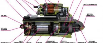
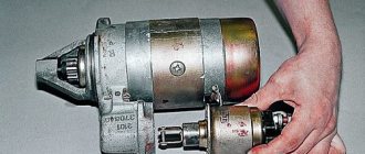
Externally, the differences between the models are expressed in the fact that in 9412.3701 the rotor impeller is located inside the housing, and the voltage regulator is mounted in the back cover. Otherwise, both models have no differences. The figure above shows the main elements:
- The voltage regulator contact is marked “B”.
- Voltage regulator.
- Contact marked “30”.
- Contact marked “61”.
- Capacitor.
- Cover (rear).
- Cover (front).
- Stator.
- Pulley.
- Stud fastening to the adjusting bar.
The rotor receives drive from the engine crankshaft using a belt drive. The generator is installed on the engine block using two bolts with nuts 17 and 19. One bolt secures the housing to the engine, the second secures it to the adjusting plate.
The electrical connection diagram for different generator models has certain differences caused by their design features, in particular the location and marking of the contacts and the location of the rectifier unit. First of all, let's look at what the connection diagram for model 372.3701 looks like.
Here numbers from 1 to 6 indicate the main elements of the power supply system:
- Accumulator battery.
- Generator.
- Mounting block with relays and fuses.
- Egnition lock.
- Measuring device for monitoring voltage (voltmeter).
- Battery charging indicator lamp.
For 9412.3701, the electrical connection diagram looks almost the same, except perhaps for the designation of the contacts. There are no differences at all in the mechanical part.
The principle of operation of the generator is to convert mechanical energy into electrical energy. Accordingly, for its effective operation it is necessary to ensure continuous transmission of torque from the VAZ 2107 engine to the generator. This is achieved by correctly adjusting the tension of the drive belt, since insufficient tension will lead to the belt slipping and loss of battery charge. This is especially critical when driving at night, when the power consumption of all systems of the VAZ 2107 car is at its maximum.
To adjust, you need to loosen both generator mounting bolts, use a pry bar to tighten the belt and secure its position with a nut on the plate. After this, we check the degree of tension: when pressing on the belt between the two pulleys, the deflection should be 10-17 mm. The adjustment procedure is repeated until the specified value is reached. After the adjustment is completed, the fastening nut to the engine housing is tightened. At this point, the installation of the generator on the VAZ 2107 is considered complete.
Source
Video - Battery protection from theft
In this article you will learn why the VAZ 2107 does not charge, as well as how to fix this problem. There are quite a few reasons for this behavior of the car’s electrical equipment, so you will have to look for a breakdown using the elimination method. It doesn't matter if the generator is working properly. It may function normally, but it will not charge. Now let's try to find out all the possible reasons.
VAZ generator wiring
A generator is an electrical device that generates electric current by converting mechanical energy. It supplies current to all electronic devices in the car and charges the battery. The conversion of motion energy into electric current occurs according to the following scheme:
- After turning the ignition key, current flows from the battery to the activation coil, through brushes and several other wire connections;
- A magnetic field is generated in the coil;
- The crankshaft spins. It is connected to the generator by a transmission belt, so its rotor also begins to spin;
- Having reached a certain limit, the rotation of the rotor leads the generator to self-activation. Subsequently, the entire electrical circuit of the car, including powerful electrical equipment, receives power from it;
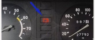
- A control indicator on the instrument panel informs the driver about the charge level in the generator.
Eliminating the causes of charging failure on the VAZ 2106
To check the electrical circuit of a car, you need a simple multimeter or voltmeter. The most common reasons for loss of charging voltage are:
- the generator belt tension is too weak or it is worn out;
- generator malfunction (brush wear, diode bridge malfunction, break or burnout of stator or armature coils);
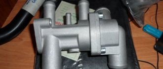
- voltage regulator malfunction;
- break in the charging circuit.
The most common cause of charging failure is a faulty voltage relay. In order to check its functionality, it will be enough to remove both wires from it, connect them together, and start the engine. Provided that all other elements in the circuit are good, the voltage in the circuit will reach about 17 V or more. If the voltage does not increase, then it is necessary to check the presence of +12 V at the terminal connected to pin 15 of the relay regulator. If it is missing, check the fuse responsible for the circuit and the integrity of this circuit itself.
If there is power at this terminal, then you need to check the connections in the generator excitation circuit. Connect a test lamp between +12 V of the battery and the wire that is connected to terminal 67 of the voltage regulator relay. In this way, you can check the voltage relay-generator circuit, as well as the serviceability of the generator brushes and its armature windings. If there is no voltage at the lamp terminals, an assumption is made that the rectifier bridge is faulty.
Next, check the serviceability of the conductor from the generator to the relay regulator. To do this check, you need to disconnect the terminal from the generator and connect it to -12 V. The glow of the control lamp indicates faulty brushes or broken armature windings. If a generator malfunction is suspected, it is removed from the vehicle and completely disassembled. Next, the serviceability of each diode in the diode bridge of the generator is checked, and the stator and armature coils are tested for breakage or burnout. Faulty elements are repaired or replaced.
The VAZ 2106 battery charging circuit provides for a constant voltage of 13.5 to 14.3 V, regardless of engine speed. However, there are cases when, at medium engine speeds, the voltage noticeably “drops” when an additional load is turned on. If such a phenomenon occurs, it is necessary to check the tension of the generator belt and adjust it. Poor contact at the battery terminals sometimes also leads to this effect.
If the voltage at the battery terminals is higher than the specified limits, you need to check all contacts, starting from the positive terminal of the battery to the voltage regulator relay. If all contacts are normal, then the relay regulator must be replaced.
Timely care of the car’s electrical equipment, the condition of the battery contacts and terminals, and regular checking of the belt tension and electrolyte level in the battery will allow your car’s engine to operate for a long time and without problems, and you will avoid many malfunctions on the road.
Components of the VAZ generator
It is installed on the engine, secured by special branches (ears) from the frame of the device, the inside of which is sealed with a rubber gasket.
The steel frame of the generator has numerous small holes that protect the unit from excessive overheating.
Unit design parts:
- The coil winding creates a magnetic field. It is made of refractory copper wire, which is hidden under a reliable heat insulator.
- Regulating relay. It accounts for the regulation of the output voltage, its strict dosing for all consumers of electricity (battery and other electronic devices). In this way, overloads are controlled and a constant network voltage is maintained (approximately 12 - 13.5V).
- Rotor – receives torque from the crankshaft, equipped with an activation winding
- Stator – also has a copper winding
- Brushes provide voltage to the rotor winding
- The bridge is a horseshoe. Consists of three pairs of electrodiodes printed on a horseshoe-shaped base.
- The pulley is designed to connect, using a multi-band belt, the generator with the crankshaft, which ensures their constant connection and synchronous rotation.
- Covers in which bearings are mounted. A capacitor is placed on one of them, damping the pulsed alternating current voltage.
VAZ generator wiring. Connection diagram
The generator has many output wires and all sorts of connectors, of different colors. There are some connection features associated with them:
- Orange wire - either needs to be connected to the gray wire (needed to autostart the engine), or left without connection.
- Gray – from relay to brushes. He's thicker than the rest
- Thin gray wire - connection to the relay
- Yellow output – indicator connection on the instrument panel
When installing it yourself, it is better to write down the purpose of all the generator wires.
The positive wire from the battery, passing through the ignition, is connected to the positive output of the generator voltage regulator. From the negative contact of the generator, the wire goes to the indicator lamp located on the panel. The other, positive, wire from the lamp is pulled to the mounting block. The negative wire of the mounting block is fixed to the negative wire of the ignition switch, where the positive wire from the generator is already connected.
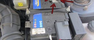
How to replace the charging relay?
- Important! First, as always, we turn off the ground, remove the negative wire from the battery terminal, then remove the yellow wire going from the generator to the relay, then use a Phillips screwdriver to unscrew it;
- Then we take it out together with the brushes:
- Now we need to carry out diagnostics. To do this, we test the voltage on the brushes with a voltmeter, and we power the relay itself from the battery, “simulating” the rectified current of the generator. At the same time, we apply (+) to terminal “B”, to the yellow wire, and connect (-) to the other terminal, “ground”. We are familiar with the signs of trouble. If you don’t have a tester, you can take a 1-3 W, 12 V light bulb.
- When installing a new relay, you need to press it firmly during installation, since new, unworn brushes provide more resistance.
If after taking these measures there is no effect, you need to look for the cause in the generator, we’ll talk about this next time. At the same time, remember that if you are removing a generator, then either you have decent knowledge in electrical engineering, or you have someone to give it to. There is no third option, especially if you have an injector.
In conclusion, let me tell you about several other reasons for the lack of charging or imitation, and also give advice:
- If you have a VAZ 2107 injector, then it is strictly not recommended to reset the battery terminal for various “checks” while the engine is running, and especially to allow strangers near the hood for this purpose. This is very harmful to electronic “brains”.
- It is advisable for those who like to “light up” to be able to say a firm “no” if you have a VAZ 2107 injector.
- On the instrument panel, the connectors are not soldered to the board, but riveted. Therefore, in some cars in the cold, while the interior is cold, there is no contact with the charging lamp. It lights up, simulating a lack of current from the generator. After the interior has warmed up, contact is restored and the lamp goes out.
- The next reason for those who like to go to the car wash in the cold. When water gets into the relay and brush assembly and freezes there, there is no charging. The solution is to heat it with any powerful hairdryer.
Precautionary measures
The voltage required to activate the generator when the ignition is on is supplied to its positive contact, having previously been connected to the control indicator. After the motor is fully started, the winding receives current from three rectifier diodes.
- The positive output of the battery must be in contact with the positive output of the generator, and the wire from the negative terminal must be connected to ground. Under no circumstances should mistakes be made, as this will entail a sharp increase in current, which will lead to damage to the generator valves.
- It is not allowed to operate the generator with the battery disconnected. Short overvoltages will damage the generator relay and electrical appliances of the vehicle network.
- It is prohibited to test the generator with electronic measuring instruments with a voltage higher than 12V. Sometimes it is necessary to check the stator windings with such devices. This can only be done with the generator disconnected.
- During welding work on the car body, all wires and contacts of the generator must be disconnected
Wiring testing. Removing the VAZ generator
All wiring problems must be identified through a thorough and step-by-step diagnosis. By checking every element of the device. And you need to start with the contacts, paying special attention to the high-voltage wires. First, arrange a visual inspection, then testing with electrical measuring instruments.
The sequence of performing such work is as follows, and each stage may be the last if the reason is found:
- Visual inspection of incoming and outgoing wires and contacts. The result may be the identification of damage, breaks, abrasion and disruption of insulation, and rebound of contacts. You can fix all these problems yourself.
- Dismantling the generator . You need to disconnect its wires leading to the battery and to the ignition switch, unscrew the nut, and remove them from the stud. Disconnect the entire block with connections from the connector. To remove the belt, to do this you need to lift the unit up as far as it will go, having first loosened the fastening with the motor cylinder. Having loosened all the fasteners, including the bolts from below, remove the generator from under the hood.
- You also need to carefully inspect the generator itself and its components. Determine wear and contamination, change (where necessary) elements and clean from soot and dirt.
- Check the output voltage changes with an oscilloscope. The graph curve, for a working generator, should be zigzag, with even teeth. If there are significant deviations, it means the stator winding .
- You also need to check the positive output of the connection to the battery; this is the output for the horseshoe diodes that provide current to the winding. The shape of the graph is sawtooth. If there are irregularities on the teeth of the graph, then there is a problem with the diodes
- the rotor winding for resistance. Clean the wires and connections, restore (if necessary) the integrity of the circuit. Use a flaw detector to check for a short circuit between the turns.
- Test rectifier valves A problematic valve will either pass current in two opposite directions (during short circuits), or will not pass current at all (during breaks). In these cases, the entire rectifier unit is replaced.
- Additional diodes are tested separately. An oscilloscope measures the voltage on each diode; it should be at least 12V. If this is not the case, then you have detected a break.
- You can check the voltage regulator without removing the generator from the car. With the engine warm, at medium speeds and headlights on, you need to use a multimeter to measure the voltage between the positive terminal and ground. If the readings do not fall within the range of 13.2 - 14.7V, the regulator must be changed, and together with the brushes
- The capacitor, in addition to protecting the generator from the pulsed nature of alternating current, provides protection against radio interference. When the fastening is loosened or the contacts come loose, radio interference increases during engine operation. We check the presence of current conductivity and measure its capacity with a special device.
- It remains to check the pulley belt for breaks and tension. A damaged belt needs to be replaced.
Electronic devices of VAZ cars
All electronic equipment of VAZ family cars operates according to the same principle. General network wiring diagrams are subject to basic rules:
- All electronic devices have a single-wire connection circuit.
- Each wire is assigned a different color and labeled with the initial letter of that color.
- The negative output is attached directly to the body. That is, the body acts as a negative channel of the circuit. It is always black.
- The positive channel comes from the battery and is marked red. You need to know this in order to take it into account when installing any device.
- The connections of each system are equipped with a wiring harness
- Any connected electronic device is under voltage due to the battery being connected to the network
- Each section of the common circuit is equipped with a fuse.
- When connecting powerful equipment, a relay is used.
These main features are inherent in both carburetor and injection engines of VAZ models.
The wiring system in injection cars has a more extensive network. This is easily explained by the presence of an electronic monitoring and control system, consisting of a control unit, numerous sensors and actuators. All this is connected to the center and to each other by a multi-meter chain of wires.
Source
Peculiarities
In VAZ 21102 cars, the electrical wiring diagram for carburetors and injectors with 8 or 16 valves is almost identical.
First, let's look at the features that characterize the Tens electrical circuit:
- All devices and equipment are powered from the on-board network. All wires are available in different colors, which greatly simplifies the repair and replacement procedure.
- The negative contact is always ground, that is, ground. The negative contacts are connected to the car body. Typically, the negative wire has black insulation.
- The positive wire is equipped with red insulation. When carrying out repairs, the wires must not be swapped.
- Any electrical equipment or system connected to the on-board network has its own wiring harness.
- The electrical circuit is designed so that when the battery is turned on, all circuits operate under voltage. Accordingly, when performing repair work on the wiring, it is advisable to disconnect the battery terminals to prevent voltage surges.
Carburetor models
The first Ten models, produced since 1998, were equipped with carburetor engines. Injectors began to appear a few years later, but carburetor versions are still widely used by our compatriots. As for the electrical wiring diagram in these cars, there are no fundamental differences in carburetor and injection internal combustion engines. There are some differences associated with the under-hood wiring; they are due to the installation of an improved ignition (author of the video channel IRON BOX).
Therefore, if you suddenly decide to change a carburetor internal combustion engine to an injection one, then most likely there will be no problems with this. The only point to consider is the connection of the fuel pump. In order for this unit to always function correctly, you need to additionally install wiring to power the device to the control module located in the car's interior.
Injector
And although the general electrical circuit of different modifications is almost identical, the latter still have their own characteristics. For example, they install a safety block that uses fusible safety parts. In addition, injection versions are equipped with a large number of different sensors and controllers to ensure optimal operation of the internal combustion engine. Due to the large number of regulators, the electrical circuit of the injection VAZ 2110 itself will be more complex. Moreover, carburetor versions do not have a control unit (ECU).
Photo gallery “Schemes for various modifications of 2110”
Connection diagram for generator in VAZ cars
The generator in cars is designed to generate electricity and charge the battery. If the normal operation of a car electric generator is disrupted, the battery begins to discharge and soon the car will stop starting completely - there is not enough battery charge. This device consists of a three-phase diode bridge, which, in turn, has 6 silicon diodes. Electrical voltage is created by the excitation of the rectifier at the moment when the rotor poles change under the stator windings. When the rotor rotates inside the machine stator, the poles of the rotor change. To increase the value of magnetic fluxes, the stator contains an electromagnetic exciting winding in the area of the magnetic cores. Marking and designation of wires:
- P - pink.
- F - purple.
- O - orange.
- B&W - black and white.
- KB - brown and white.
- CHG - black and blue.
- K - brown.
- H - black.
- B - white.
Generator device
The design of a car generator implies the presence of its own rectifier and control circuit. The generating part of the generator, using a stationary winding (stator), generates three-phase alternating current, which is then rectified by a series of six large diodes and the direct current charges the battery. Alternating current is induced by the rotating magnetic field of the winding (around the field winding or rotor). Next, the current is supplied to the electronic circuit through the brushes and slip rings.
Generator structure: 1.Nut. 2. Washer. 3.Pulley 4.Front cover. 5. Distance ring. 6.Rotor. 7.Stator. 8.Back cover. 9.Casing. 10. Gasket. 11.Protective sleeve. 12. Rectifier unit with capacitor. 13.Latch holder with voltage regulator.
The generator is located at the front of the car engine and is started using the crankshaft. The connection diagram and operating principle of a car generator are the same for any car. There are, of course, some differences, but they are usually associated with the quality of the manufactured product, the power and the layout of the components in the motor. All modern cars are equipped with alternating current generator sets, which include not only the generator itself, but also a voltage regulator. The regulator equally distributes the current in the excitation winding, and it is due to this that the power of the generator set itself fluctuates at a time when the voltage at the power output terminals remains unchanged.
Connection diagram for the VAZ-2101 generator
Structurally, generator 2101 consists of the following main elements:
- The rotor is a moving part that rotates from the engine crankshaft. Has an excitation winding.
- The stator is the stationary part of the generator and also has a winding.
- Front and rear covers , inside of which bearings are installed. They have eyelets for attaching to the internal combustion engine. The back cover contains a capacitor necessary to cut off the alternating current component.
- Semiconductor bridge - called a “horseshoe” for its similarity. Three pairs of semiconductor power diodes are mounted on a horseshoe-shaped base.
- A pulley on which the VAZ-2101 generator belt is placed. The belt is V-shaped (on modern cars a multi-ribbed belt is used).
- The voltage regulator is installed in the engine compartment, away from the generator. But still it must be considered part of the structure.
- The brushes are mounted inside the generator and transmit the supply voltage to the field winding (on the rotor).
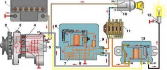
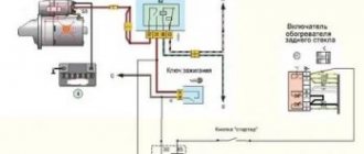
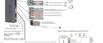
Connection diagram for the VAZ-2107 generator
1 - battery; 2 - negative diode; 3 - additional diode; 4 - generator; 5 - positive diode; 6 - stator winding; 7 - voltage regulator; 8 — rotor winding; 9 — capacitor for suppressing radio interference; 10 — mounting block; 11 — battery charge indicator lamp in the instrument cluster; 12 - voltmeter; 13 — ignition relay; 14 - ignition switch.
Understanding the reasons for charging problems on the VAZ 2106
To check the electrical circuit of a car, you need a simple multimeter or voltmeter. The most common reasons for low charging voltage are:
- The generator belt tension is too weak or too worn;
- generator malfunction (worn brushes, faulty diode bridge, broken or burnt stator or armature coils);
- voltage regulator malfunction;
- shaving in charging area.
The most common cause of charging failure is a malfunction of the voltage relay. In order to verify its usefulness, it will be enough to remove the grudge from the grudge, put it together, and start the engine. Because of the fact that all other elements of the lance are attached, the voltage in the lance is close to 17 or more. If the voltage does not increase, then it is necessary to check the presence of 12 V at the terminal connected to pin 15 of the relay regulator. If necessary, check the lance, which confirms the lance and the very integrity of this lance.
If the device is connected to this terminal, it is necessary to check the connection in the generator wake-up circuit. Connect the test lamp between the 12 V rechargeable battery and the dart, which connects to connection 67 of the voltage regulator relay. In this way, you can check the voltage relay-generator circuit, as well as check the generator brushes and armature windings. If there is no voltage at the lamp pins, worry about a malfunction of the direct bridge.
Next, check the serviceability of the conductor from the generator to the relay regulator. For such verification it is necessary to disconnect the terminal from the generator and connect it to -12 Art. The indicator light is on to indicate faulty brushes or broken armature windings. If a malfunction of the generator is suspected, it should be removed from the vehicle and examined further. Next, check the integrity of the diode in the diode bridge of the generator, check the continuity of the stator coils and armatures for damage or burnout. Faulty elements must be repaired or replaced.
The VAZ 2106 battery charging circuit shows a constant voltage of 13.5 to 14.3, regardless of engine speed. However, there are breakdowns when the voltage on the middle turns of the engine noticeably “sags” when the additional voltage is turned on. If such a phenomenon occurs, it is necessary to check the tension of the generator belt and adjust it. Weak contact at the battery terminals can also lead to this effect.
Since the voltage at the battery terminals is higher than the specified values, you need to check all contacts, starting from the positive terminal of the battery to the voltage regulator relay. If all contacts are normal, then the relay regulator prompts replacement.
Keeping an eye on your car's electrical system, the contacts and terminals of the battery, regularly checking the belt tension and the level of the electrolyte in the battery will allow your car's engine to run smoothly and without problems, and you will avoid a bug atoch malfunctions in dozі.
Connection diagram for the VAZ-2108 generator
The VAZ-2108 generator has a rather massive stator winding, since it uses a large cross-section wire. It is with its help that electricity is generated. The wire is wound evenly over the entire inner surface of the stator into recesses specially provided for this purpose in the magnetic core. It’s worth talking about the latter separately. The middle part, the generator stator, consists of a series of thin metal plates pressed tightly together. They are often boiled on the outside to prevent separation.
Troubleshooting algorithm
There is no need to think that charging is not happening for some very serious reason. Immediately check the condition of fuse F10, which is responsible for powering the excitation winding of the VAZ 2107 generator. But before doing this, it is better to make sure that the drive belt is intact and its tension is normal. But also pay attention to the fact that you cannot over-tighten it - there will be no recharging of the battery (provided that the regulator is operating in the intended mode), but the bearings will fail much faster.
If charging is not going well, the lamp, for example, burns at half intensity, then the fault must be looked for in the wiring. Namely, in the connections between the battery and the car body. Very often oxidation occurs, which prevents normal contact. Unscrew the nut, thoroughly clean the terminal and body surface, and then install the wire in place.
But if everything is fine with the switching, but charging still does not occur, you need to look further for the reason. And the first thing to suspect is the voltage regulator. With its help, the voltage at the generator output is stabilized. If this element fails, the battery overcharges or it does not charge well. Repair of this element is impossible, and the price in stores will be about 300 rubles. There are several options for regulators:
- A separate unit - installed on the body of a VAZ 2107 car.
- Combined with brushes - mounted directly in the generator.
How to check the regulator will be discussed in a separate article. If it is working properly, but charging still does not occur, or it is there, but it does not flow to the battery well, look for a fault in the brush assembly. It is quite possible that the wires that connect the brushes to the contacts have broken. But the most common thing is excessive wear or clogged brushes.
Somewhat less often, failure of the diode bridge or destruction of the stator or rotor windings occurs. To determine these breakdowns, you will need to completely disassemble the generator and carry out diagnostics using a tester and megger. Along the way, of course, it is best to replace the bearings in the VAZ 2107 generator.
Connection diagram for the VAZ-2109 generator
- Alternator. The 37.3701 or 94.3701 series can be installed.
- Negative diode.
- Additional diode.
- Positive diode.
- Alternator warning lamp, also known as battery discharge lamp.
- Instrument cluster.
- Voltmeter.
- Relay and fuse box located in the engine compartment in the compartment between the engine and the vehicle interior.
- Additional resistors built into the fuse mounting block.
- Ignition relay.
- Egnition lock.
- Accumulator battery.
- Capacitor.
- Rotor winding.
- The voltage relay is located in the engine compartment.
Connection diagram for the VAZ-2110 generator
On VAZ-2110, 2111 and 2112 cars, a 94.3701 generator was installed with a maximum output current of 80 Amperes and a voltage = 13.2–14.7 Volts.
Here is a breakdown of the connection diagram for the generator on the ten :
- Battery 12V;
- generator 94.3701;
- mounting block;
- egnition lock;
- battery charge indicator lamp in the instrument cluster
What wires go to the VAZ 2106 generator
Seasoned Zhigulist
Group: Zhigulists Messages: 1149 Registration: 12.5.2009 From: Ekaterinburg User No.: 13768 Car: VAZ 2106 Color: Cherry Year of Issue: 1995 Thanks said: 4 times
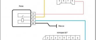
Here is a diagram for connecting the generator excitation based on the original wiring. No relays are needed. Suitable for connecting generators from 21214, 2110(12), 2108, 2107 and similar.
Fig. 1 Connection diagram for the VAZ 2101 (G-221) generator 1 – battery; 2 – generator; 3 – voltage regulator; 4 – ignition switch; 5 – fuse block; 6 – battery charge indicator lamp (in the instrument cluster); 7 – relay of the RS-702 signaling device.
Fig. 2 Diagram for connecting generator 21214 based on wiring 2101 1 – battery; 2 – generator; 4 – ignition switch; 5 – fuse block; 6 – battery charge indicator lamp (in the instrument cluster), please note the lamp should be set to 4W; 7 – diode (in5007). Almost any diode can be used. 8 - resistor 51Ohm 5W (5W51RJ)
The housing for the resistor and diode can be made from an old RS-702 relay and placed in its place
We won't need the orange wire.
This way you can connect the orange wire to the gray wire directly. and use it for something. I connected autostart using it (in everyday life, of course, the case is closed)
We bite off the “-” (white-black) from the charge lamp and solder a new wire. Which we connect to fuse 9 or 10
Photo bonus. This happens when the “+” wire is shortened to the “pants”
Ask. Together we will correct and close the topic so as not to create a flood.
Post edited by Lev_Ekb
— 20.4.2010, 18:26
How to check the generator yourself
How to check a VAZ generator using the example of model 2109. Generator type 94.3701 alternating current, three-phase, with a built-in rectifier unit and an electronic voltage regulator, right-hand rotation.
Generator connection diagram . The voltage to excite the generator when the ignition is turned on is supplied to terminal “D+” of the regulator (terminal “D” of the generator) through indicator lamp 4 located in the instrument cluster. After starting the engine, the excitation winding is powered by three additional diodes installed on the generator rectifier block. The operation of the generator is controlled by a warning lamp in the instrument cluster. When the ignition is turned on, the lamp should be on, and after starting the engine, it should go out if the generator is working. If the lamp is brightly lit or glows half-lit, it indicates a malfunction.
The “minus” of the battery should always be connected to ground, and the “plus” should always be connected to the “B+” terminal of the generator. Failure to turn the battery back on will immediately cause increased current through the generator valves and damage them.
It is not allowed to operate the generator with the battery disconnected. This will cause short-term overvoltages to occur at the “B+” terminal of the generator, which can damage the generator voltage regulator and electronic devices in the vehicle’s on-board network.
It is prohibited to check the functionality of the generator “for spark” even by briefly connecting the “B+” terminal of the generator to ground. In this case, significant current flows through the valves and they are damaged.
Checking generator operation
You can check the functionality of the generator in several ways using certain methods, for example: you can check the output current of the generator, the voltage drop on the wire that connects the current output of the generator to the battery, or check the regulated voltage.
To check, you will need a multimeter, a car battery and a lamp with soldered wires, wires for connecting between the generator and the battery, and you can also take a drill with a suitable head, since you may have to twist the rotor by the nut on the pulley.
Basic check with a light bulb and multimeter
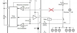
Connection diagram: output terminal (B+) and rotor (D+). The lamp must be connected between the main output of the generator B+ and contact D+. After this, we take the power wires and connect the “minus” to the negative terminal of the battery and to the generator ground, the “plus”, respectively, to the plus of the generator and to the B+ output of the generator. We fix it on a vice and connect it.
We turn on the tester in DC mode, attach one probe to the battery to “plus”, and the second one too, but to “minus”. Next, if everything is in working order, then the light should light up, the voltage in this case will be 12.4V. Then we take a drill and start turning the generator, accordingly, the light bulb will stop burning at this moment, and the voltage will already be 14.9V. Then we add a load, take an H4 hologen lamp and hang it on the battery terminal, it should light up. Then we connect the drill in the same order and the voltage on the voltmeter will show 13.9V. In passive mode, the battery under the light bulb gives 12.2V, and when we turn it with a drill, it gives 13.9V.
Generator test circuit
Strictly not recommended:
- Check the functionality of the generator by short circuit, that is, “to spark”.
- It is also undesirable to allow the generator to operate without consumers turned on; it is also undesirable to operate with the battery disconnected.
- Connect terminal “30” (in some cases B+) to ground or terminal “67” (in some cases D+).
- Carry out welding work on the car body with the generator and battery wires connected.
In this article you will learn why the VAZ 2107 does not charge, as well as how to fix this problem. There are quite a few reasons for this behavior of the car’s electrical equipment, so you will have to look for a breakdown using the elimination method. It doesn't matter if the generator is working properly. It may function normally, but it will not charge. Now let's try to find out all the possible reasons.
Replacement and removal of the electric generator
The generator on a VAZ car is removed either for complete replacement in case of failure or to carry out repair work to replace faulty parts. To perform dismantling, prepare a standard set of tools; it is advisable to drive the car into the inspection hole.
- Disconnect the battery.
- Remove the protective rubber cap from terminal “30” and unscrew the nut and remove it from the wire stud.
- Disconnect the block with wires from the generator connector.
- We loosen the tightening of the generator to the adjusting bar, then lift it all the way up to the cylinder block and remove the belt from the pulleys.
- Completely unscrew the bolt securing the adjusting bar to the cylinder block, then from the bottom of the car unscrew the 2 bolts securing the lower bracket to the block and remove the generator, pulling it out of the engine compartment.
Source