Electrical circuits
Generator
- accumulator battery;
- generator;
- battery charge indicator lamp located in the instrument cluster;
- mounting block;
- ignition switch
Lighting and light signaling
- block headlights;
- mounting block;
- headlight switch;
- ignition switch;
- outdoor light switch
- high beam headlight warning lamp in the instrument cluster;
- K4 – headlight low beam relay;
- K5 – headlight high beam relay;
- A – to power supplies
External lighting switching diagram
- side light lamps in headlights;
- engine compartment lamp;
- engine compartment lamp switch;
- mounting block;
- ignition switch;
- outdoor lighting switch;
- side light lamps in the rear lights;
- brake lamps in the rear lights;
- additional brake signal;
- license plate lights;
- control lamp for turning on the outside lights in the instrument cluster;
- brake light switch
- K1 – lamp health monitoring relay (contact jumpers are shown inside the relay, which must be installed in the absence of a relay);
- A – to power supplies;
- B – to instrument lighting lamps
Direction indicator switching diagram
- turn signal lamps in headlights;
- ignition switch;
- turn signal switch;
- side direction indicators;
- turn signal lamps in the rear lights;
- hazard switch;
- instrument cluster with turn signal and hazard warning lamps;
- mounting block;
- K3 – relay-interrupter for direction indicators and hazard warning lights;
- A – to power supplies
Scheme for switching on headlight correctors
- motor reducer for headlight level control;
- mounting block;
- headlight switch;
- ignition switch;
- outdoor lighting switch;
- headlight leveling control;
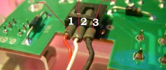
Plus and minus limit switches - what is their difference
To replace the sensor, you need to determine its polarity. Limit switches with plus and minus work according to the same scheme. In domestic transport, negative devices are installed and a short circuit to ground occurs. The Volga car and some foreign models have positive polarity. The test is carried out using a special device. The main causes of the malfunction: mechanical damage, wear or lack of contact of the wiring.
Finding the switch will allow you to disassemble the door card and remove the trim. If there is a break, then the current stops flowing to the relay coil, and the power supply to the loading electromagnet is turned off. Sometimes it is enough to replace the wires or lubricate it for proper operation to resume. Search process:
- Open the car door.
- Test each wire with a voltmeter.
- If +12V appears on the scale, then the sensor is positive.
The alarm system that the switch is directly connected to will not operate correctly if the switch is damaged or inoperative. Risks:
- the automatic door lock will break;
- if there is a break-in, the alarm will not go off;
- the lights will not light up;
To find, replace or modify the sensor, you need to study the alarm circuit. It shows the exact location of the devices. To determine the location, craftsmen use an ammeter, regardless of which surface the device is located in: rear or front.
Symptoms of problems with the immo system on a Chevrolet Niva are usually the following:
- The Check Engine indicator or immobilizer icon lights up on the instrument panel.
- The key installed in the lock does not allow starting the power unit of the car. The engine does not start and the crankshaft does not turn. Sometimes such problems can be regarded as a malfunction of the starter or battery.
The indicator on the dashboard can light up for various reasons, including if the light bulb itself is faulty.
Causes of malfunctions
The main causes of the problem:
- Discharge of the power supply in the blocker control key fob.
- Damage to the tag in the key. Because of this, the microprocessor control module cannot identify the car owner.
- Mechanical malfunctions - damage to the key itself or the control unit of the system. Contacts may oxidize or defects may appear on them. If the control unit is exposed to moisture, it may become flooded.
- Malfunction of the electrical component. This refers to the wires used to connect the blocker - they can be damaged.
- Software malfunctions of the control unit.
User Alexander Zakharov showed one of the signs of a malfunction in the operation of the Niva engine blocking device.
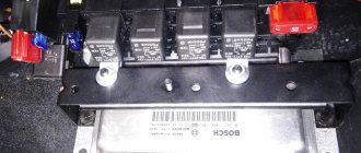
Pinout of contacts of the Niva Chevrolet fuse mounting block
The car is supplied to the market with several types of mounting blocks. The exact type of device depends on the configuration of the vehicle and its year of manufacture. Further description is given using the example of Bosch M,1,5,4:
- 1 – cylinder ignition system;
- 2 – empty;
- 3 – fuel pump connection contact;
- 4 – stepper motor;
- 5 – free;
- 6 – connection of the main power plant cooling fuse;
- 7 – incoming pulse from the MRI;
- 8 – empty;
- 9 – standard speedometer;
- 10 – not busy;
- 11 – knock sensor;
- 12 – voltage supply for sensors;
- 13 – L-line;
- 14 – weight on the body from the injectors;
- 15 – control of injector drives for cylinders 1-4;
- 16/17 – not used;
- 18 – power supply of devices from 12 volts;
- 19 – common ground cable for electrical appliances;
- 20 – ignition supply to cylinders 2 and 3;
- 21 – stepper motor terminal;
- 22 – engine check lamp;
- 23 – empty;
- 24 – mass of the stepper motor;
- 25 – air conditioning system relay output;
- 26/29 – stepper power plant;
- 27 – voltage to terminal No. 15 of the ignition switch;
- 28 – empty;
- 30 – mass of motor control sensors;
- 31/32 – not applicable;
- 33 – control of settings of injector drivers for cylinders No. 2/3;
- 34-36 – empty;
- 37 – device for powering the main relay;
- 38-40 – not used;
- 41 – submitting a request for an air conditioning module inside the cabin;
- 42 – empty;
- 43 – tachometer control signal;
- 44 – signal supply from the potentiometer;
- 45 – DTOZH;
- 46 – control of the main relay;
- 47 – device for confirming admission to ECU programming;
- 48 – low level of impulse from DPKV;
- 49 – opposite meaning;
- 50-52 – empty;
- 53 – receiving an impulse from the TPS;
- 54 – fuel consumption detail;
- 55 – K-line.
Electrical wiring components
The standard Niva Chevrolet wiring diagram is divided into several sections for better maintainability and ease of maintenance.
- Front part - a set of cables connects all equipment located in the engine compartment of the car.
- The interior part - the unit is additionally divided into independent zones, which allows you to power different groups of equipment without the risk of damaging or overloading the main elements.
- Instrument panel compartment - a bundle of cables combines the lines from all gauges, sensors and indicators.
- The stern assembly - the bundle is responsible for voltage and control of equipment located on the rear side of the vehicle.
How to change a light bulb in a panel on a Niva?
To replace the lamp in the dashboard on a Chevrolet Niva, you need to remove the panel from the car. To do this, dismantle the cladding and then remove the shield.
Unfold the shield and find the required cartridge. Remove the cartridge by turning it counterclockwise. You need to remove the baseless lamp from the socket and install a new one in its place:
After this, you need to install the shield in its original place and reassemble it in the reverse order.
Tuning options
The choice of options for tuning is not particularly large:
- Install a device from another car. In this case, you will need the services of a qualified electrician, since the connectors will have to be redone. You can also install a digital version of the tidy - it will be more than original.
- As a tuning option, you can install LED bulbs instead of regular ones. Many car owners choose this option because it is less expensive and the easiest to implement.
- Another tuning method is to install original instrument scales on the speedometer, tachometer and other sensors. Moreover, you can buy such scales either ready-made or make them yourself in accordance with your preferences.
https://www.youtube.com/watch?v=lOrs5QhybBQ
1. Tidy with LED lighting
2. Digital control panel
3. Tidying with the so-called. wells
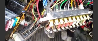
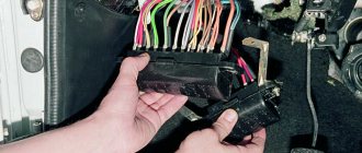
Where are the fuse box and relays of the Niva Chevrolet
The location of the inserts on cars has not changed from 2011 to 2021.
To gain access to the main unit, you should pick the instrument panel in the area of the pedal assembly. Under the dashboard, to the left of the steering wheel. To get to the panel under the tidy, use a Phillips screwdriver to remove the plastic casing, where the panel will be.
A detailed location with a description is in the photo below.
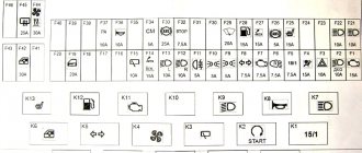
Chevrolet Niva fuses with description
The main elements of a car can be divided into two groups based on location. Consequently, their purpose will be different.
The photo shows a fuse panel, relevant for models manufactured after 2009. For convenience, it is better to give the decoding in the form of a table.
| Number | Circuit Description |
| F1 | License plate lighting, side lights on the left side of the car. |
| F2-4 | The main lighting is low beam, high beam and fog lamps on the left side of the car. In some configurations, fuse No. 4 is a spare socket. |
| F5 | Main power window protection relay |
| F6 | Cigarette lighter power supply. Some motorists connect power cores here instead of an incandescent filament. |
| F7 | Horn connection relay. |
| F8 | Heated rear glass and rear view mirrors. |
| F9 | Interior lighting switch, glove compartment lighting, wiper drive and electrics. Separate outlet for windshield washer system compressor. |
| F10 | Standard control module for electrical accessories and door locking, or spare |
| F11-14 | Exterior car lighting. Low and high beam head optics, fog lights, side lights. The fuses are responsible for the right side of the vehicle. |
| F15 | Standard control system for rear view mirror drives. Fuse for heated seats. The minimum configuration does not include the insert. |
| F16 | Hazard warning light breakers and turn relays |
| F17 | Interior lighting, partial display of the instrument panel, alarm position control, brake signals, additional stop block. |
| F18 | Power heating fan |
| F19 | Starter head relay, instrument panel lighting and indication, turn signal relay system in turn mode. |
| F20 | Rear fog lamps, immobilizer and anti-theft alarm buzzer. |
The car radio and speedometer are connected separately from the main fuses. The drives of the injectors and air conditioning compressor are designed similarly. Depending on the configuration and year of manufacture, the listed components may be connected according to a different scheme.
Also in the VAZ 2123 panel there are spare fuses located in separate sockets.
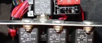
Additional fuse block
Here the main part is represented by relays, but there are also fuses. Fuse links have markings and areas of responsibility:
- No. 2 – high-power fuse responsible for protecting the power lines of the electrical circuit of the right radiator fan and an additional relay group;
- No. 3 – safety insert for the fuel pump located in the tank;
- No. 4 – the element is responsible for powering the car controller circuit;
- No. 9 – fuse for the right radiator fan;
- No. 10 – insert protecting power lines and circuits switched on by the main relay.
Relay Niva Chevrolet
Two places where protective inserts of electrical circuits are concentrated are presented. The explanation of the automatic circuit switching nodes is as follows.
Main mounting block.
| Designation in the diagram | Decoding of the serviced circuit and equipment |
| K1 | Mostly not used, but in some configurations it can be connected. |
| K2 | Window cleaning system, relay powers electric motor. |
| K3 | Turn signal breaker in working position |
| K4 | Headlight module - low beam switching on |
| K5 | Protective switch for turning on and powering the high beam head optics |
| K6 | An additional relay is responsible for the operation of several nodes simultaneously. Typically, the heated glass of the aft part, the fan drive of the heating system, and the windshield and rear window washers are connected here. |
| K7 | In some configurations it acts as a fuse for the heating element of the cargo compartment door. |
| K8 | Not used |
The car’s design also includes a remote control panel:
- K1/2 – standard fog lights (if equipped);
- K3 – activation of the seat heating system;
- K4 – horn protection;
- K5 – standard inclusion of the starter circuit.
Separately, you should consider the engine control system unit:
- K1 – additional relay;
- K5-6 – head radiator fan inserts for the left and right sides, respectively;
- K7 – power supply to the fuel pump circuit;
- K8 is the main relay of the car.
Electrical Harness System
Due to the ignition system, a spark appears in the cylinders corresponding to the current power strokes. In modern engines, wires go to sensors that are responsible for monitoring several indicators:
- Motor temperature.
- Ignition, and so on. The injector also becomes an important part.
The ignition system harness is in most cases connected to several other parts:
- controller;
- instrument panels;
- "mass".
Next, the wires are sent to the rear harness. Moving on to the engine compartment, the main harness splits into two wires. Of these, the largest is sent to the radiator, connecting with the following components along the way:
- DMRV.
- Crankshaft sensor.
- Resistor.
- Electric fans.
Through the power steering pump, other wires are thrown from the core, going to additional sensors:
- phases;
- idle move;
- throttle valve;
- detonation;
- injectors - a fuse for them is not added to the system.
Due to the wiring, the operation of the engine is clearly controlled. Ensures uninterrupted operation regardless of environmental conditions.
The second core goes up, after which it is divided into two parts. The wires to the plus and minus go to the right. The battery is also located there. To the left they connect to the adsorber, fuel pressure sensor and oxygen sensor. This is how electrical wiring is arranged in most cases.
And also interesting: Niva 2121, Niva 2131 and Niva Chevrolet. Let's compare?
A branch from the harness may go to the air conditioning fuse if the car is equipped with such equipment.
If even one part of this system shorts, there is a high probability that the engine simply will not start. The controller stops seeing information regarding temperature, fuel supply to the injectors, and throttle valve position.
Under such circumstances, it is better not to resort to diagnostics, but to replace the entire harness at once. It may take too much time to find one wire, and the result will be questionable. The wiring works better when new.
Consumers.
All consumers are connected in parallel to each other and, for convenience, are combined into separate blocks. Each block has its own fuse. This arrangement increases safety and also simplifies maintenance.
The Chevrolet Niva fuse box is a separately mounted unit located in the passenger compartment. Almost all circuits, except for the charging and engine starting circuit, are protected by fuses.
The Chevrolet Niva starter provides the initial start of the engine by engaging the wire gear with the flywheel. Fundamentally, it works like a DC motor, in which the role of the rotor is played by the winding, and the stator is played by permanent magnets. Such a motor is capable of developing power up to 1.5 kW with a current of 80 A. But these are only nominal figures.
The role of the key for some circuits is played by the ignition switch. In this case, it is multifunctional, since it combines a locking device, a starter key, and a restart lock. The ignition key closes almost all circuits. The circuit that provides interior lighting, central locking, brake lights, and an engine compartment light remains energized. The Chevrolet Niva immobilizer is activated using inductive communication between the key transponder and the anti-theft system unit.
Headlights, fog lights and tail lights form the exterior lighting of the vehicle. The headlight has built-in low and high beam bulbs. Separate optics allow more efficient control of light beams, providing increased lighting efficiency. The side lights are also mounted in the headlight housing. PTFs are not included in the standard package and are an additional option.
The front windshield wipers operate in three modes: intermittent, normal and accelerated. The motors of the front and rear windshield wipers are protected by thermobimetallic fuses.
Switching operating modes is carried out by control levers on the steering column of the car. The glass washer system works together with the brushes. The front and rear washer motors are built into the windshield washer fluid reservoirs. The reservoir for the front glass is located in the engine compartment, and for the rear – in the trunk door.
The window regulators are driven by a reverse gear motor. It operates on a pulse signal and has feedback. The gear motor turns off when the glass reaches one of the extreme positions.
The Chevrolet Niva dashboard controls the operation of functionally important systems.
It combines a speedometer, tachometer, thermometer, and fuel level indicator. In addition, there is a liquid crystal display, which displays information from the on-board computer about the ambient temperature and the current time. Critical values of some parameters are duplicated by signal lamps. Panel maintenance only involves replacing lamps. The rest of the work is not regulated, and the entire device is changed.
Ignition switch Niva Chevrolet
On VAZ 2123 (Chevrolet Niva) cars, an ignition switch type 2123–3704005 is used with an anti-theft locking device, a lock against re-starting the starter without first turning off the ignition, and a communication coil for the ignition key transponder with the car's anti-theft system.
Connection diagram of the ignition switch Niva Chevrolet
At the ignition switch, check the correct closure of the contacts at different key positions, the operation of the anti-theft device and the presence of communication with the car anti-theft system. The voltage from the battery and generator is supplied to terminal “30”.
Switched circuits at different positions of the Chevy Niva key
To unload the contacts of the Niva Chevrolet ignition switch, a K6 relay is installed in the mounting block. The anti-theft locking rod should extend when the key is turned to position 0 (off) and removed from the lock. The locking rod must be recessed after turning the key from position 0 (off) to position I (ignition). The key must only be removed from the lock in position 0. The locking device against reactivation of the starter must not allow the key to be turned again from position I (ignition) to position II (starter). Such a rotation should only be possible after first returning the key to position 0 (off).
Replacing the ignition switch Niva Chevrolet
Remove the upper and lower steering column housings
Disconnect the block with the ignition switch wires from the wiring harness
Disconnect the block with the ignition switch wires from the Chevy Niva ignition relay
Remove using a chisel or screwdriver and hammer, or drill out four self-cutting bolts. Remove the ignition switch from the steering column. Installation of the Niva Chevrolet ignition switch is carried out in the reverse order of removal, after first recessing the locking rod of the anti-theft device. To do this, insert the key into the switch and turn it from position “0”. The Chevy Niva ignition switch pinout diagram will help you avoid getting confused in connecting the ignition switch.
Prevention
To prevent breakdowns, the manufacturer recommends following several tips.
- Once a year, treat all terminals and connectors with special oil - this will prevent the formation of oxides.
- Periodically check the tightness of the contact connectors. If the connections are loosened, short circuits may form or the conductivity of the circuit may decrease, which will be perceived by the ECU as a mechanism failure.
- Check the degree of wear of power cables and lines. During active use of the vehicle, braids made of flexible polymer may wear out and crack. This circumstance can provoke short circuits and mechanical shedding of insulators. Therefore, it is better to prevent a breakdown than to fix it.
Modernization of the heating device in a Chevrolet Niva car
Before the heater is improved, it is necessary to understand the principle of operation of the dampers. Then you should completely dismantle the decorative panels located on the left side of the Chevrolet Niva stove. The next step is to remove the regulator responsible for the position of the dampers. When optimizing your car, you need to understand the design of the heating device, which will allow you to dismantle the “unnecessary” equipment without unnecessary delays. The motorist must remove the lower part of the regulator, through which the front flap is activated.
When dismantling all the plastic elements, you should not try to abruptly remove the parts, since almost all the components of the device being disassembled are made of fragile plastic, which breaks even under more or less significant impact. If, however, due to haste or carelessness of the owner of the movable property, the lower part of the device being removed gets a crack, it can be hidden with a soldering iron.
Modifying the Chevrolet Niva stove with your own hands involves the need to secure the lower damper so that it is tightly closed in the upper position. Of course, such a modernization completely eliminates the ability of the motorist to take advantage of the “front” position, however, it provides many other more significant advantages.
Once the “front” of the stove is in the closed position, you will need to think through the trajectory of the element that regulates the simultaneous supply of heat to the glass and legs. It is worth noting that skilled craftsmen, when upgrading their Chevrolet Niva, use all available means, in particular, an ordinary discount card will be useful for optimizing the stove. By means of which a cut line is drawn, then the element is glued with cyanoacrylate and filed to size with a file.
The modification of the Chevrolet Niva heater should be completed after the hand-cut part is glued with superglue.
Video: Replacing the Ignition Switch Chevrolet Niva With Immobilizer
You will need a chisel (hammer), hammer and screwdriver to remove it. Using a chisel and hammer, make a cut on the head of the bolt, the chisel should be held at an angle so that the blow does not accidentally hit, and not directly into the head of the bolt. Once the cut is complete, you need to place the chisel in it and hit the head with a hammer to turn the head counterclockwise.
For reference. Since the bolts are frequently attached, it may be a waste to pre-treat the bolt heads with WD-40 to make them easier to remove.
After making the bolt easier, you can unscrew it using pliers (pliers). The procedure is then repeated with the remaining three bolts. The biggest difficulties arise when twisting the upper right bolt, since access to it is difficult. To remove it from the mount, you can use a screwdriver, which can then be replaced with a chisel (punch).
Warning. If you can't get the bolts out, you'll need to sharpen the heads with a file or knock them down with a hammer and chisel.
After removing the bracket, you must use a Phillips screwdriver to remove the bolts that secure the contact group. After this, the dismantled lock can be disassembled and inspected for damage to its cylinder and stopper (pins). When the key is inserted into the cylinder, the plugs must be removed; if this does not happen, then you can try to feed them. However, in this case it is impossible to overdo it. Excessively applied pins will cause the cylinder to slip when turning the key.
Installing a new lock and reassembling it is done in the reverse order.
- The cylinder must be inserted into the lock and its functionality must be checked. When the key is inserted, the locking pins must be removed and the key must be returned to the cylinder without restriction or slippage.
- A contact group is connected to the lock and is attached to the steering shaft.
- The mounting bracket is attached to unscrew bolts.
- The protective cover is mounted.
For reference. Since the cylinder has been replaced, you will need to use different ignition keys and doors. To use one key, you will need to replace the door lock and trunk cylinders.
How to replace the Chevrolet Niva ignition switch with an immobilizer
For all Chevrolet Niva variants, the factory-installed immobilizer is installed in the usual way. an anti-theft device that blocks the engine from starting when the transponder key is outside the range of the immobilizer antenna.
Replacing the Chevrolet Niva ignition switch with an immobilizer is complicated by the fact that the training key is not suitable for the new cylinder. Accordingly, it is impossible to recognize the new key, so the immobilizer will not allow you to start the engine.
Chevrolet Niva wiring diagram, part of the ECM
- 1 – spark plug pins;
- 2 – contact group of injector drivers;
- 3 – ignition unit;
- 4 – control controller;
- 5 – main protective relay of the internal combustion engine;
- 6 – area for location of fuse links;
- 7 – main relay fuse;
- 8/9 – protective circuits of the right and left head fans of the radiator;
- 10 – protective element for the control fuse of the main fuel pump;
- 11 – controller circuit fuse;
- 12 – secondary protective element of the main radiator fan on the right side;
- 13 – auxiliary fuse of the above circuit;
- 14 – fusible link of the fuel pump control circuit;
- 15 – fan of the main radiator, located on the left side;
- 16 – standard oxygen concentration sensor in the intake manifold;
- 17 – drain output of the detonation channel meter;
- 18 – DPKV output;
- 19 – control by the adsorber purge valve;
- 20 – output of the mass air flow sensor group;
- 21 – idle speed control drive;
- 22/23 – activation of the left/right fan motor of the main engine cooling system;
- 24 – auxiliary resistor;
- 25 – control of the TPS device;
- 26 – output from antifreeze temperature sensor;
- 27 – status indicator of the above-described sensor;
- 28 – standard module for measuring lubricant pressure in the crankcase compartment of the power plant;
- A/B – battery terminal blocks;
- C – “mother” input for connecting to the dashboard;
- G 1/ G 2 – grounding outputs of the wiring section.
Instrument panel pinout
Here is a description of the terminals and terminals of standard instrument panel wiring:
- 1 – diagnostic output, located on the underside of the board under the steering wheel;
- 2 – plug connector for connecting the ECM;
- 3/4 – standard modules for connecting the front connection of the cores responsible for the engine control systems;
- 5/7 – left and right steering column switches;
- 6 – ignition switch device connector;
- 8 – instrument panel combination;
- 9 – output for powering the connector of the contact group of the interior ventilation and heating system;
- 10/11 – lighting plugs for the above equipment;
- 12 – button switch of the alarm device;
- 13 – mounting box for fuse insertion;
- 14/15 – the lamp itself and the button to turn off the lighting of the glove compartment;
- 16 – contact pin for turning off the brake lights;
- 17 – switch of the standard sound warning module (horn);
- 18 – automatic protection of fog lights of head optics;
- 19 – automatic window lifters;
- 20 – protective relay for sound signal;
- 21 – safety module for the seat heating system;
- 22 – starter control relay;
- 23 – switch for the external lighting system;
- 24 – contact group for connecting the stove fan;
- 25 – built-in switch for turning on the heated windshield;
- 26 – device for turning off the front fog lights;
- 27 – switch for stern lights, fog lighting group;
- 28 – air conditioner setting button;
- 29 – position regulator of heating manipulators;
- 30 – cigarette lighter pin;
- 31 – buttons for adjusting the direction of the light flux of the head optics;
- 32 – adjust the brightness of the instrument panel illumination;
- 33 – auxiliary resistor mechanism of the heating fan;
- 34 – standard immobilizer module;
- 35/36 – standard-type onboard acoustic module terminals;
- 37/38 – terminal connectors for connecting the rear harness of the on-board circuit.
And also interesting: Niva Chevrolet engine - Niva Chevrolet (VAZ 2123, Chevy)
Common faults
If everything is clear with the description, then let's talk about breakdowns. There can be many faults in the electrical circuit. But they are all divided into several groups. If, for example, you doubt the performance of the spark plugs, and the spark plugs themselves, as it turned out as a result of the test, are operational, then you need to check the high-voltage wires. Failures in the operation of this or that equipment may be caused by failure of the device itself, improper operation of the battery or generator.
Let's start with the battery, its typical faults:
- the occurrence of a short circuit between the electrodes of the structure;
- the structural plates were damaged;
- cracks have formed on the battery body;
- The battery terminals have become acidic (the author of the video is Boris Anisimov).
All this can lead to battery drain. As for the reasons, if the battery has not yet exhausted its service life, then most likely they are a violation of the rules of use, as well as manufacturing defects.
To use the battery correctly, you must consider several rules:
- the electrical wiring system must function only with a working generator unit, otherwise the battery will be overcharged or discharged;
- destruction and acidification of contacts is facilitated by poor contact at the terminal of the structure;
- deep discharge of the device can be caused by frequent starts of the power unit or an attempt to start it by prolonged operation of the starter;
- In addition, the service life of the device may be reduced due to its poor fixation in the engine compartment.
On average, the service life of a battery is about 3-4 years. But the service life may be reduced as a result of intensive use, as well as the use of the battery in harsh conditions. In any case, all breakdowns have only one consequence - the battery will not be able to crank the starter mechanism and provide the electrical equipment of the vehicle with current. If the battery is working normally, then perhaps the cause of the problem lies in the generator unit.
Since its design itself is more complex, the generator also has more breakdowns:
- breakdown of current collecting brushes;
- failure of the regulator relay;
- breakdown of the diode bridge;
- failure of slip rings (their wear);
- bearing element failure;
- problems in the operation of the pulley due to damage to its teeth or wear;
- a short circuit has occurred in the stator winding;
- The charging circuit cables may be damaged (video author: Chevy Niva repair).
If the problem is a bearing, the generator as a whole will be much louder. As for other breakdowns, they can be checked by low voltage levels. The corresponding indicator on the control panel will light up.
You can repair the device yourself, since the design of almost all generators is the same, and the repair procedure is generally universal. In this article, it is described using the example of a VAZ 2114 car. If you have never encountered such a task, then it is better to seek help from a qualified electrician.
Ignition switch (lock) Niva Chevrolet
On VAZ-2123 vehicles, an ignition switch of type 2123–3704005 is used with an anti-theft locking device, a lock against re-starting the starter without first turning off the ignition, and a communication coil for the ignition key transponder with the automobile anti-theft system.
Rice. 1. Connection diagram of the ignition switch (with the key inserted)
At the ignition switch, check the correct closure of the contacts at various key positions (Table 1), the operation of the anti-theft device and the presence of communication with the automobile anti-theft system.
The voltage from the battery and generator is supplied to contact “30” (Fig. 1).
Connection between battery and starter
Each car has its own starter installation scheme. There may be several access options:
- on right;
- left;
- from the radiator side;
- from the salon side.
It is often necessary to use a lift or inspection hole to reach this component. The mechanism is needed to ensure engagement between the gear and the flywheel. Therefore, the device is most often located in the area where the clutch housing is attached. The electronic version is no exception.
For connection, only one connector is used, to which a special terminal is added. The starter starts working every time the owner turns the key.
It is best to use a multimeter to detect breakdowns in one of these parts of the car. But faults can be easily determined using other simple manipulations.
In most cases, repairing the starter is possible, even if such an important part as the windings has failed. The electrical equipment of a car in most areas is subject to complete restoration.
Functionality of the standard multimedia system
In short, we can highlight the main functions that the multimedia system performs:
- Multimedia;
- Navigation system;
- Bluetooth + E-Link connection with phone;
- Display image when reversing + obstacle detection.
Quite a modern multimedia with, in our opinion, an exhaustive list of what an MMC should be able to do. Well, probably all that remains is to add output of sensor readings to the display. But that is another story. Here we will not stop and analyze what and how it works there, but will limit ourselves to just a general listing, and will try to pay more attention to the installation process.
By the way, most likely you have one more question: what cars can you install it on? So, the position of the plant, reflected in the technical specifications for installation, is as follows:
On our own behalf, we can add that, at first glance, this device can be adapted to any Shevik. At least, after sitting and thinking about the connection methods and components, we did not find anything that would prevent us from using it on earlier models: power connectors from a regular radio, everything else is included, the panel at the installation site did not change much. The only hassle that we think may arise is installing a rear view camera. If your car does not have harnesses for parking sensors and a camera, and you would like to be able to use this function, you will have to tinker.
A little about the electrical equipment of the VAZ-2123
Complicated at first glance, but simple for an understanding person, a map that helps to find a fault. First, you need to determine the node in which the breakdown occurred, and then, using the rescue scheme, find all the elements associated with it and their location.
The electrical equipment of the Chevrolet Niva is made according to a single-wire circuit: the negative leads from sources and consuming mechanisms are connected to the body and the unit itself, which acts as a second wire. Rated DC voltage of 12 V – on-board network. During the “sleep” of the engine, all electronics are powered by the battery, and after starting, the flow is switched to the alternating current generator, which has a built-in voltage regulator and rectifier.
Most electrical circuits are protected by fuses for safety reasons. The exceptions are the following chains:
- battery charge;
- starting the engine;
- generator
The following are additionally protected by automatic bimetallic fuses:
- electric motors;
- gear motor for windshield wipers, as well as rear door glass.
Most energy consumed:
- headlights;
- air conditioning;
- electric fuel pump;
- electric motors of some devices, etc.
Most of the “defenders” are arranged in a grouped manner. The fuse mounting block is located in the passenger compartment, under the instrument panel, on the left side of the steering column. The table attached to the diagram shows the rated current of the fuses and the circuits they protect from overload. The powertrain control fuse and relay box is attached to the controller bracket.
Problems when paying with bank cards
Sometimes difficulties may arise when paying with Visa/MasterCard bank cards. The most common of them:
- There is a restriction on the card for paying for online purchases
- A plastic card is not intended for making payments online.
- The plastic card is not activated for making payments online.
- There are not enough funds on the plastic card.
In order to solve these problems, you need to call or write to the technical support of the bank where you are served. Bank specialists will help you resolve them and make payments.
That's basically it. The entire process of paying for a book in PDF format on car repair on our website takes 1-2 minutes.
If you still have any questions, you can ask them using the feedback form, or write us an email at