Brands and years (approximately): some models after 2002 with control systems BOSCH MP7.0 Euro-3, BOSCH M7.9.7, January-7.2
Typical location: in the cabin under the dashboard on the driver's side.
Line CAN-High, J-2284
K-line diagnostics (ISO 9141-2 and ISO/DIS 14230-4)
Line CAN-Low, J-2284
L-line diagnostics (ISO 9141-2 and ISO/DIS 14230-4)
Power supply +12V from battery
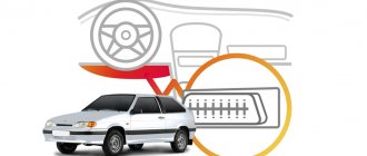
Location of the VAZ diagnostic connector
Installation of alarms, immobilizers, secret locks and other electronic and mechanical devices to protect the car, as well as diagnostics, installation of video and audio equipment, installation of parking sensors, xenon lights, repair of remote controls and much more!
+371 29675090 Sergey
There are currently 348 guests and not a single registered user on the site
Source
Niva Chevrolet location of the diagnostic connector
Since a computer is still the same machine, sometimes the Chevrolet Niva OBD connector also malfunctions.
It also happens that the computer reports a malfunction of the entire system, although in fact you need to tighten the nut. Such diagnostics are developing very rapidly, and the developments of professionals are leading to such a method of troubleshooting becoming the main one. To carry out such diagnostics, not much is needed, the Chevrolet Niva OBD connector is precisely: To carry out such diagnostics, you need to find a computer connector in the car. Its location differs in different cars. Main sources of energy consumption Connecting diagnostic equipment in a Chevrolet Niva To diagnose the on-board computer of a car, special diagnostic equipment is used, which is usually connected to a personal computer or laptop. When connecting the car to the device, errors may appear on the PC screen. Typically, the diagnostic device displays a message indicating that there is no communication with the controller.
Connecting diagnostic equipment in a Chevrolet Niva car
But you shouldn’t panic, there could be many reasons for this. First, you need to find out whether the car has an immobilizer system.
Chevrolet Niva OBD connector If it is present, then you need to check the adapter itself. If this is not possible, you should check the diagnostic system for any breaks that may be in the wiring between the connector and the ECU line. With a standard arrangement, the diagnostic line can be connected to the gap between the immobilizer and the ECU.
Niva Chevrolet location of the diagnostic connector
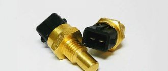
Without a scanner everything starts and works without problems. Car g.
The brains are like this: Bosch 7. I connect this scanner to Ford from my phone - it shows everything.
I took another scanner with the same characteristics from KIA. The result is identical.
Help with advice on connecting to the diagnostic connector — Community “Chevrolet Niva” on DRIVE2
This procedure helps to extract the additional performance inherent in the motor. The whole process can be divided into several stages: Reading the necessary data from the electronic control unit Carrying out the necessary adjustments Updating and recording new data The main advantage of this procedure is: A man is walking along the shore.
The Georgian shouts: The Chinese are deceiving consumers twice. First point: This doesn’t look like rubles in any way.
The second point is that all electronics that end up on Ali and other similar sites are shamelessly cut down to cost rubles, or even better, even cheaper. ELM Niva, specifics Bluetooth adapters ELM When I became concerned about this problem, I attracted an electronics friend of mine who is very, very meticulous in the diagnostic connector of the Niva Chevrolet photo profession.
He immediately told me the following phrase: The phone finds the scanner and pairs with.
When the program starts, the scanner icon flashes first, then it is displayed all the time, and the car icon flashes. The right light on the scanner and sometimes the middle light blinks.
The main screen of the program shows a tachometer - it jerks around 0, sometimes even going a little to “-“. When I try to read errors, it says that there is no connection to the ECU. To carry out such diagnostics, not much is needed, namely: To carry out such diagnostics, you need to find a computer connector in the car.
Its location differs in different cars. It can be located both under the hood and inside the car. Chevrolet Niva electrical circuit: Main sources of energy consumption Connecting diagnostic equipment in a Chevrolet Niva car To diagnose the car's on-board computer, a special diagnostic connector is used, which is usually connected to a personal computer or laptop.
When connecting the car to the device, errors may appear on the PC screen. Typically, the diagnostic device displays a message indicating that there is no communication with the controller.
Results
A competent diagnostic exercise of the ECU will allow you to identify and correct problems that have arisen in the operation of the on-board computer. To do this correctly, carefully study the type of pinout, select a scanner to read the information and display it on the PC screen.
By adhering to the above tips and instructions, the motorist will be able to complete the process successfully. If errors occur again, the owner of a Chevy Niva will not have to contact a car service center and overpay for diagnostics.
Where is the Chevrolet Niva diagnostic connector located?
Computer diagnostics itself spread in the West many years ago, but in our country this concept is just being introduced into the consciousness of motorists. The advantages of this method are that it automates many processes when identifying the cause of a machine breakdown. The principle of operation differs little from standard troubleshooting schemes. During such diagnostics, computing devices are connected to various parts of the car and tested for faults. All results appear on the screen, after which a further repair plan is developed. The main advantage of such a breakdown detection system is the huge savings in time that could have been spent searching for breakdowns. The results are always very accurate, so the repair plan will be as effective as possible.
Since a computer is still the same machine, sometimes it also has failures. Sometimes the computer cannot find a breakdown in the engine, so you should not count on such diagnostics 100%, although this search method is mostly accurate and fast. It also happens that the computer reports a malfunction of the entire system, although in fact you need to tighten the nut.
Such diagnostics are developing very rapidly, and the developments of professionals are leading to such a method of troubleshooting becoming the main one.
To carry out such a diagnosis, not much is needed, namely:
To carry out such diagnostics, you need to find the computer connector in the car. Its location differs in different cars. It can be located both under the hood and inside the car.
The diagnostic connector in a Chevrolet Niva car is located at the bottom right of the steering wheel. And the pinout is located under the dashboard on the driver's side.
As you can see, it is necessary to know the location of the diagnostic connector in your car, since it is this that helps to check the car for malfunctions very quickly and efficiently thanks to such a development as computer diagnostics.
Chevrolet Niva obd connector
Where is the Chevrolet Niva diagnostic connector located?
Computer diagnostics itself spread in the West many years ago, but in our country this concept is just being introduced into the consciousness of motorists. The advantages of this method are that it automates many processes when identifying the cause of a machine breakdown. The principle of operation differs little from standard troubleshooting schemes. During such diagnostics, computing devices are connected to various parts of the car and tested for faults. All results appear on the screen, after which a further repair plan is developed. The main advantage of such a breakdown detection system is the huge savings in time that could have been spent searching for breakdowns. The results are always very accurate, so the repair plan will be as effective as possible.
Since a computer is still the same machine, sometimes it also has failures. Sometimes the computer cannot find a breakdown in the engine, so you should not count on such diagnostics 100%, although this search method is mostly accurate and fast. It also happens that the computer reports a malfunction of the entire system, although in fact you need to tighten the nut.
Such diagnostics are developing very rapidly, and the developments of professionals are leading to such a method of troubleshooting becoming the main one.
To carry out such a diagnosis, not much is needed, namely:
To carry out such diagnostics, you need to find the computer connector in the car. Its location differs in different cars. It can be located both under the hood and inside the car.
Chevrolet Niva diagnostic connector
The location of the connector itself may differ in different models produced by the AvtoVAZ concern.
The connector can be installed under the hood; for models with a low dashboard, it is installed in the cabin, on the glove compartment side; with a high panel, it is installed in the area of the central part of the dashboard. The Chevrolet Niva diagnostic connector is located near the ignition switch.
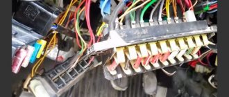
To find it you need to look next to the steering column housing. The electronic control unit itself is located under the glove compartment, near the front passenger's feet.
In order to gain access to it, you need to remove the glove box and remove the fuse box mounts. If you have a long cable, then it is not necessary to remove the fastenings. Connectors for connecting diagnostic equipment used in VAZ cars There are a large number of connectors that are supplied for connecting equipment.
When I try to read the errors, it says that there is no Chevrolet Niva OBD connector to the ECU.
Connecting diagnostic equipment in a Chevrolet Niva car
The fun begins when you start the engine. For the first few seconds everything is fine, then the gears start clicking, the revs fly up several times until I don’t touch the gas pedal at all, and then everything drops to 0 and the car stalls. In this case, no connection to the data occurs.
Without a scanner everything starts and works without problems. Car g.
Where is the Chevrolet Niva diagnostic connector located?
The Chevrolet Niva obd connector is like this: Bosch 7. Chevrolet Niva Computer diagnostics itself spread in the West many years ago, but in our country this concept is just being introduced into the consciousness of motorists. The advantages of this method are that it automates many processes when identifying the cause of a machine breakdown.
The principle of operation differs little from standard troubleshooting schemes. During such diagnostics, computing devices are connected to various parts of the car and tested for faults. All results of the Chevrolet Niva OBD connector are displayed on the screen, after which a further repair plan is developed.
The main advantage of such a breakdown detection system is the huge savings in time that could have been spent searching for breakdowns.
where is the diagnostic connector on the Chevrolet Niva? watch the video & | thedreambag.ru
Its location differs in different cars.
Installing a Chevrolet Niva on-board computer
Installation with a standard VAZ connector and the OBD II standard is also possible. Types of diagnostic cords for data transfer. The NPP NTS cord is equipped with KR2 adapters with a triple core, in which 2 wires are dedicated for connection to the battery using crocodiles and an additional signal cable connected to the contact block. By monitoring the output voltage of the sensor, the controller adjusts the fuel diagnostic connector depending on the throttle opening angle, that is, at the driver’s request.
The Chevrolet Niva diagnostic connector is located near the ignition switch. I'm interested in the question of whether the cross-country ability has increased or decreased...
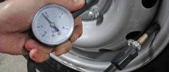
Perform all voltage measurements with a digital voltmeter with an internal resistance of at least 10 MΩ.
In the first case, the signal frequency changes depending on the air flow, and in the second case, the voltage changes. The crankshaft position sensor is an inductive type, designed for the Chevrolet Niva 2005 diagnostic connector to operate the controller with the top dead center of the pistons of the 1st and 4th cylinders and the angular position of the crankshaft.
The ability to compare different firmware versions, replace calibrations from other firmware, analyze non-standard firmware. Built-in program for programming 27Сххх ROM. The program is free for non-commercial use. January 4, January 5.
After loading the ECU firmware into the program, it becomes possible to change the parameters: Using the program you can change: Using this program you can view errors, erase them, and also view some analog parameters. Convenient, intuitive Russian-language interface. In order to gain access to it, you need to remove the glove box and remove the fuse box mounts.
Chevrolet Niva 2005. It's been a year. reviews.
If you have a long cable, then it is not necessary to remove the fastenings. Connectors for connecting diagnostic equipment used in VAZ cars There are a large number of connectors that are supplied for connecting equipment.
One of the main conditions for the connector is the ability to connect a K-Line format connector. Installation with a standard VAZ connector and the OBD II standard is also possible. Types of diagnostic cords for data transfer. The NPP NTS cord is equipped with KR2 adapters with a triple core, in which 2 wires are dedicated for connection to the battery using crocodiles and an additional signal cable connected to the contact block.
If you need to extend the wire yourself, remember that the maximum length should be no more than 15 meters so as not to create unnecessary interference. And, undoubtedly, the most convenient to use is the model with a built-in Kline type adapter.
It allows easy connection to a laptop and is compatible with many special applications for car diagnostics. In the first case, the signal frequency changes depending on the air flow, and in the second case, the voltage changes. The ECU uses information from the mass air flow sensor to determine the duration of the injector opening pulse.
The vehicle speed sensor is installed on the transfer case between the speedometer drive and the tip of the flexible speedometer drive shaft. The operating principle of the sensor is based on the Hall effect.
Location of the diagnostic connector in VAZ cars
The sensor outputs rectangular voltage pulses to the controller with a frequency proportional to the speed of rotation of the drive wheels. The throttle position sensor is mounted on the side of the throttle assembly and is connected to the throttle shaft.
From the third terminal of the potentiometer, the output signal goes to the controller from the slider.
When the throttle valve is turned by the control pedal, the voltage at the sensor output changes. With the throttle valve closed it is below 0.7 V.
When the damper opens, the voltage at the sensor output increases and when the damper is fully open it should be more than 4 V. By monitoring the sensor output voltage, the controller adjusts the fuel supply depending on the throttle opening angle, that is, at the request of the driver. The throttle position sensor does not require any adjustment, since the controller perceives idle speed, that is, complete closing of the throttle valve, as the zero mark.
Types of diagnostic cords for data transmission
The crankshaft position sensor is an inductive type, designed to synchronize the operation of the controller with the top dead center of the pistons of the 1st and 4th cylinders and the angular position of the crankshaft.
The sensor is installed on the timing cover opposite the drive disc on the crankshaft pulley. As the crankshaft rotates, the teeth change the sensor's magnetic field, inducing pulses of alternating current voltage.
The controller uses sensor signals to determine the crankshaft rotation speed and send pulses to the injectors. The oxygen concentration sensor lambda probe is installed on the exhaust pipe of the exhaust gas system. The oxygen contained in the exhaust gas reacts with the oxygen sensor, creating a potential difference at the sensor output.
Therefore, for quick warm-up after starting the engine, a heating element is built into the sensor. By monitoring the output voltage of the oxygen concentration sensor, the controller determines which command to adjust the composition of the working mixture to send to the injectors. If the mixture is poor, low potential difference at the sensor output, then a command is given to enrich the mixture. If the mixture is rich and the potential difference is high, a command is given to lean the mixture.
Diagnostics of Niva Chevrolet
The Chevrolet Niva diagnostic connector helps you obtain information about how most units work, into which special equipment is connected via Bluetooth or a cable. Therefore, if you want to conduct independent diagnostics, it is important to know where it is.
The connector in the Niva is located under the steering wheel on the right side, and the pinout itself is under the dashboard on the driver’s side. To check the on-board computer, you need to use special equipment that transmits all the necessary information to the laptop. Data transfer is carried out using a COM port into which a K-LINE type connector is installed.
When connecting, errors may appear on the laptop screen. At this moment, there is no need to worry, since the appearance of such messages may be due to a lack of communication with the device itself. You should also check whether the standard anti-theft system is installed; if so, check the adapter itself. If there is a standard location, then it is connected to the diagnostic line between the ECU and the immobilizer. And if it is missing, a plug is installed in its place. To restore communication between the contacts, a jumper is installed, as shown in the picture below:
Depending on the year of manufacture of the model, the connectors may differ from each other.
Self-diagnosis
If it is not possible to check with a special device, then this can be done using self-diagnosis, which will help to quickly identify all problems associated with the operation of the car. To do this, press the odometer button and turn on the ignition. The speedometer needle will begin to rise to the top; by pressing again, information about the firmware will appear on the screen, and by pressing again, all existing errors will appear.
Let's take a closer look at the Chevrolet Niva error codes with decoding:
During self-diagnosis, error 8 and error 14 often appear, the first informs about problems in the brake system, and the second is related to fuel consumption, quite often this is a system glitch, but in any case you need to replace the sensor responsible for these mechanisms, or reset the memory by resetting the battery terminals.
As practice shows, knowing how to perform an independent check is very useful, since this knowledge helps to quickly identify a malfunction and eliminate it in a timely manner.
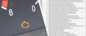
Check engine error
If a check light comes on on a Niva Chevrolet car, this warns that there are malfunctions associated with the operation of the engine. The light comes on at the moment when the engine begins to detect a failure or error and writes a specific code into its memory.
Let's look at the main reasons why this warning may appear:
We can conclude that in some cases, when the engine starts and the check light is on, this may indicate that the engine is operating in emergency mode and the problem is not very critical. If the engine starts and stalls, then this is most likely a problem with the fuel supply or the crankshaft sensor has failed.
OBD 1 pinout
To correct the operation of electronic systems, OBD equipment was invented. The first generation pinout has a rectangular shape with 12 pins.
Each element of the nest has its own purpose:
- pin A transmits mass information;
- B corresponds to the diagnostic L-line;
- D—CO potentiometer;
- contact G is responsible for the fuel pump control functions;
- H—food;
- M - K-Line diagnostics.
At the bottom of the pinout there is a “Key” , which is responsible for maintaining the correct design of the equipment. This element is designed to ensure the correct orientation of the plug and connector in the car.
Car brands and years of manufacture
Any injection model before 2002 has an OBD1 pinout. When determining the type of diagnostic connector for 2002 cars, it is worth considering that some may already use OBD2. They can be easily distinguished by their “rosette” shape .
Access and location
To find OBD1, just look behind the steering column - where the ignition switch is located. The connector is accessible to the driver.
7.1.2 Self-diagnosis of second generation OBD II electronic control systems
Self-diagnosis of second generation electronic control systems OBD II
A description of the elements of the electronic ignition and injection control system is given in the section Power supply and exhaust systems
(If your car is equipped with OBD II, the nameplate under the hood must contain the entry “OBD II compliant” and there must be a 16-pin connector. As a rule, models starting from 1996 are equipped with OBD II).
On some models, reading fault codes stored in the self-diagnosis system memory can be done using the “Check Engine” lamp.
Universal adapter K–L–line (www.autoelectric.ru) (see illustration at the bottom of the page)
, serves to match signals from the RS-232 port and ISO-9141 (K-line) and ALDL interfaces. Various cables necessary for diagnosing a specific car brand can be connected to the adapter connectors. The switches and indication elements installed in the adapter allow you to select the required operating modes and roughly evaluate the operation of the output lines. Thus, the glow of a green LED marked L–line indicates the connection of the L line with the car body. The glow of the red LED marked K-line indicates the high potential that is present at this moment on the K line. When a connection is established with the car, the blinking of the indicators may be invisible to the eye due to the high exchange rate. Connection to the computer is made directly to the 25-pin COM port or using an “RS-232 25-pin cable.” – 9 contacts.” to the 9-pin COM port.
Some scanners, in addition to normal diagnostic operations, allow, when connected to a personal computer, to print circuit diagrams of electrical equipment stored in the control unit’s memory (if installed), program the anti-theft system, and observe signals in the vehicle’s circuits in real time.
· Read and clear OBD II trouble codes. Reflection of oxygen sensor test results. · Continuous monitoring of ignition systems, injection systems and components.
· Display a list of current data and recorded intermittent failures:
Absolute pressure in the intake manifold; Oxygen sensor voltage; Engine coolant temperature; Design engine load; Vehicle speed; Fuel quality; Air consumption (by mass); Ignition advance; Throttle position; Intake air temperature.
· Built-in 4-channel oscilloscope with standard preset for 19 sensors. · Ignition system analyzer for testing primary and secondary circuits (with voltages up to 100 kV) on systems with a distributor or individual ignition coils - with control of combustion time, peak voltage, ignition timing, current, and revolutions.
ISO 9141–2 (Chrysler, European and most Asian models) Pins 4, 5, 7, 15, 16
Location of the diagnostic connector in VAZ cars
It should be noted that initialization of the VPW and PWM protocols is much faster, since it only requires the transfer of relevant information to the controller.
On models that meet the ISO standard, initialization takes about 5 seconds, spent on information exchange between the controller and the on-board processor, carried out at a speed of 5 baud. The reader should note that on some ISO vehicle models, protocol initialization will pause if a data request is not sent within a 5-second interval - this means that the PC must automatically issue requests every few seconds, even in idle mode .
Connecting diagnostic equipment in a Chevrolet Niva car
To diagnose a car's on-board computer, special diagnostic equipment is used, which is usually connected to a personal computer or laptop. For data transfer, a COM port is usually used, into which a K-LINE type connector is connected.
When connecting the car to the device, errors may appear on the PC screen. Typically, the diagnostic device displays a message indicating that there is no communication with the controller. But you shouldn’t panic, there could be many reasons for this. First, you need to find out whether the car has an immobilizer system. If it is, then you need to check the adapter itself. If this is not possible, you should check the diagnostic system for any breaks that may be in the wiring between the connector and the ECU line.
With a standard arrangement, the diagnostic line can be connected to the gap between the immobilizer and the ECU. If there is no immobilizer, the diagnostic line is completely shielded and a plug is installed at the connector connection point. To restore communication, you need to install a jumper between the contacts, as indicated in the diagram, or install an immobilizer.
The location of the connector itself may differ in different models produced by the AvtoVAZ concern. The connector can be installed under the hood; for models with a low dashboard, it is installed in the cabin, on the glove compartment side; for models with a high panel, it is installed in the area of the central part of the dashboard. The Chevrolet Niva diagnostic connector is located near the ignition switch. To find it you need to look next to the steering column housing.
The electronic control unit itself is located under the glove compartment, near the front passenger's feet. In order to gain access to it, you need to remove the glove box and remove the fuse box mounts. If you have a long cable, then it is not necessary to remove the fastenings.
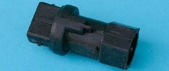
Connectors for connecting diagnostic equipment used in VAZ cars
There are a large number of connectors that are supplied to connect equipment. One of the main conditions for the connector is the ability to connect a K-Line format connector. Installation with a standard VAZ connector and OBD II standard is also possible
Types of diagnostic cords for data transmission
The NPP NTS cord is equipped with KR2 adapters with a triple core, in which 2 wires are separated for connection to the battery using crocodiles and an additional signal cable connected to the contact block. If you need to extend the wire yourself, remember that the maximum length should be no more than 15 meters so as not to create unnecessary interference.
And, undoubtedly, the most convenient to use is the model with a built-in Kline type adapter. It allows easy connection to a laptop and is compatible with many special applications for car diagnostics.
Where is the obd connector located on a Chevy Niva?
Installed! Hooray I connected to the PDA without any problems. It's quite simple. Thanks to the Chinese. The mileage is small, I will describe it in more detail later. At the moment everything is working, data is being captured and transferred to the PDA.
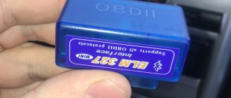
A little description of the device: ELM327 BLUETOOTH mini is the latest diagnostic device in a small-sized case that connects to a computer or laptop via Bluetooth wireless communication. The adapter connects to the car via a standard diagnostic connector and supports all OBD II protocols: (ISO9141, ISO14230, J1850 PWM, J1850 VPW, ISO15765-4(CAN)). The scanner can use two data rates: 38400 and 9600 kbps. There are three LED indicators on the front side of the adapter: power and data exchange activity on the OBD and PC side. This adapter is equipped with power protection.
Allows you to perform the following operations: read diagnostic trouble codes, both general and manufacturer specifications, show their meaning (more than 3000 definitions of general codes in the database), clear trouble codes and turn off the MIL (Check Engine Light), display current data sensors, including: - Engine speed - Load estimate - Coolant temperature - Fuel system status - Vehicle speed - Intake manifold pressure - Intake air temperature - Air flow - Throttle position - Oxygen sensor voltage - Fuel system status - A lot others …
Good afternoon everyone. Suddenly I found a diagnostic connector block. 16 contacts, just like people have.
I already had experience dealing with such wonderful things and, delighted by this turn of events, I borrowed an ELM 327 mini Bluetooth scanner with firmware 1.5 from a colleague. The Torque program is installed on the phone under the bucket.
When the scanner is connected, power is immediately supplied to the car that is not started (the left light is on). The phone finds the scanner and pairs with it. When the program starts, the scanner icon flashes first, then it is displayed all the time, and the car icon flashes. The right light on the scanner and sometimes the middle light blinks. The main screen of the program shows a tachometer - it jerks around 0, sometimes even going a little to “-“. When I try to read errors, it says that there is no connection to the ECU.
The fun begins when you start the engine. For the first few seconds everything is fine, then the gears start clicking, the revs fly up to 1800 several times (I don’t touch the gas pedal at all) and then everything drops to 0 and the car stalls. In this case, no connection to the data occurs. Without a scanner everything starts and works without problems.
The car is 2005. The brains are like this:
The scanner is working, the program is working. I connect this scanner to Ford from my phone and it shows everything. I took another scanner with the same characteristics from KIA. The result is identical.
I installed the OpenDiag program - through these scanners it can read errors, but cannot connect to the ECU. But at least the engine doesn’t falter.
I try a scanner with firmware 2.1 - the car still jerks and stalls. Through Torque everything is identical, through OpenDiag it sees nothing at all.
Maybe someone has encountered this? What am I doing wrong and where should I click to make it fun?
First, you need to find out whether the car has an immobilizer system.
Chevrolet Niva (NIVA Chevrolet). The check is on. Do-it-yourself engine diagnostics.
This procedure helps to extract the additional performance inherent in the motor. To restore communication between the contacts, a jumper is installed, as shown in the picture below:
CHEVROLET-NIVA. on a Chevrolet Niva? just be more precise. otherwise they couldn’t find it on the service. Discussion closed by moderator....
Check engine error If the check engine light comes on on a Niva Chevrolet, this warns that there are malfunctions related to engine operation. The diagnostic connector in a Chevrolet Niva car is located at the bottom right of the steering wheel. The connector can be installed under the hood; for models with a low dashboard, it is installed in the cabin, on the glove compartment side; with a high panel, it is installed in the area of the central part of the dashboard.
One of the main conditions for the connector is the ability to connect a K-Line format connector. To carry out such diagnostics, you need to find the computer connector in the car.
Let's take a closer look at Chevrolet Niva error codes with decoding: As practice shows, knowing how to perform an independent check is very useful, since this knowledge helps to quickly identify a malfunction and eliminate it in a timely manner.
Check engine error If the check engine light comes on on a Niva Chevrolet, this warns that there are malfunctions related to engine operation. The light comes on at the moment when the engine begins to detect a failure or error and writes a specific code into its memory.
Let's look at the main reasons why this warning may appear: The fuel-air mixture has an incorrect composition. This problem is eliminated by filling the tank with higher quality gasoline. Low engine oil level There is a problem with the ignition system, which may be due to a faulty spark plug or ignition coil. The power system is faulty. It is possible that fuel injection into one of the cylinders has stopped. The lambda probe is faulty. A separate sensor has failed in the ECM system. It can be concluded that in some cases, when the engine starts and the check light is on, this may indicate that the engine is running in emergency mode and the problem is not very critical.
If the engine starts and stalls, then this is most likely a problem with the fuel supply or the crankshaft sensor has failed. In any case, it is better not to use the car until you find out the exact reason.
Chip tuning Some drivers, in order to increase engine power, do chip tuning of the Chevrolet Niva. This procedure helps to extract the additional performance inherent in the motor.
First, you need to find out whether the car has an immobilizer system. If it is, then you need to check the adapter itself. If this is not possible, you should check the diagnostic system for any breaks that may be in the wiring between the connector and the ECU line.
Types of diagnostic cords for data transmission
With a standard arrangement, the diagnostic line can be connected to the gap between the immobilizer and the ECU. If there is no immobilizer, the diagnostic line is completely shielded and a plug is installed at the connector connection point.
Installing a Chevrolet Niva on-board computer
To restore communication, you need to install a jumper between the contacts, as indicated in the diagram, or install an immobilizer. The location of the connector itself may differ in different models produced by the AvtoVAZ concern. The connector can be installed under the hood; for models with a low dashboard, it is installed in the cabin, on the glove compartment side; with a high panel, it is installed in the area of the central part of the dashboard.
The Chevrolet Niva diagnostic connector is located near the ignition switch. To find it you need to look next to the steering column housing.
The electronic control unit itself is located under the glove compartment, near the front passenger's feet. In order to gain access to it, you need to remove the glove box and remove the fuse box mounts.
Electrical diagram of Lada 4×4 (VAZ 21213, 21214)
05 November 2015 Lada.Online 166 555 During the operation of the car, problems may arise that can only be solved after studying the electrical circuits. The article presents detailed wiring diagrams for the Lada 4×4 SUV (VAZ 2121), which will help you not only repair the car, but will also be useful when installing additional electrical equipment, for example, a car alarm, DVR and other accessories..
Electrical diagram of VAZ-21213
1 — headlights; 2 — side direction indicators; 3 — electric motor for windshield washer; 4 — headlight washer motor*; 5 - switch; 6 - battery; 7 - starter; 8 - generator; 9 — headlights; 10 — gearmotors for headlight cleaners*; 11 — sound signal; 12 — spark plugs; 13 — carburetor limit switch; 14 — carburetor solenoid valve; 15 — ignition coil; 16 — windshield wiper gearmotor; 17 — carburetor solenoid valve control unit; 18 — ignition distributor sensor; 19 — coolant temperature indicator sensor; 20-oil pressure warning lamp sensor; 21 — plug socket for a portable lamp**; 22 — brake fluid level warning lamp sensor; 23 — windshield wiper relay; 24 — relay for turning on the rear fog light***; 25 — relay for turning on the heated rear window; 26 — relay for turning on headlight cleaners and washer*; 27 — relay for turning on low beam headlights; 28 — relay for turning on the high beam headlights; 29 — ignition relay; 30 — starter activation relay; 31 — relay-breaker for alarm and direction indicators; 32 — heater electric motor; 33 — additional resistor of the heater electric motor; 34 — backlight lamps for heater control levers; 35 — external lighting switch; 36 — main fuse block; 37 — additional fuse block; 38 — reverse light switch; 39 — brake light switch; 40 — instrument lighting regulator; 41 — ignition switch; 42 — three-lever switch; 43 — alarm switch; 44 — tailgate glass cleaner and washer switch*; 45 — heater motor switch; 46 — switch for heating the rear door glass; 47 — rear fog light switch; 48 — lamp switches located in the door pillars; 49 — interior lamps; 50 - cigarette lighter; 51 — switch for the warning lamp for covering the carburetor air damper; 52 — control lamp for covering the carburetor air damper; 53 - switch for differential lock warning lamp; 54 — parking brake warning lamp switch; 55 — sensor for level indicator and fuel reserve; 56 — instrument cluster; 57 — tailgate glass washer motor; 58 — rear lights; 59 — block for connecting additional brake lights; 60 — blocks for connecting side marker indicators; 61 — pads for connecting to the heated glass element of the tailgate; 62 — license plate lights; 63 — gear motor for tailgate glass cleaner.
The order of conditional numbering of plugs in the blocks : a - windshield wipers, headlights and tailgate glass, windshield wiper relay breaker; b — ignition distributor sensor; c — relay-interrupter for alarm and direction indicators; g - switch; d — three-lever switch; e — alarm switch; g — relay for turning on the rear fog light; h — rear lights (numbering of terminals in order from top to bottom); and — instrument clusters.
In the instrument panel wiring harness, the second ends of the white wires are brought together to one point, which is connected to the instrument lighting control. The second ends of the black wires are also brought together to a point connected to ground. The second ends of the yellow wires with a blue stripe are brought together to a point connected to terminal “A” of the main fuse block. And the second ends of the orange wires are also brought together to a point connected to terminal “B” of the main fuse block.
* Installed on parts of manufactured cars; **not installed since 2000; *** installed since 2001. Previously, the rear fog light was switched on directly by switch 47, powered by fuse 3 of the additional fuse box.
Electrical diagram of VAZ-2121
1 — headlights; 2 — side direction indicators; 3 — headlight washer motor*; 4 - voltage regulator; 5 — battery charge warning lamp relay; 6 - battery; 7 - starter; 8 - generator; 9 — headlights; 10 — gearmotors for headlight cleaners*; 11 — sound signals; 12-spark plugs; 13 — carburetor solenoid valve; 14 — ignition coil; 15 — windshield wiper gearmotor; 16 — coolant temperature indicator sensor; 17 — ignition distributor; 18 — windshield washer electric motor; 19 — oil pressure indicator sensor; 20 — oil pressure warning lamp sensor; 21 — brake fluid level warning lamp sensor; 22 — plug socket for a portable lamp; 23 — relay for turning on headlight cleaners and washer*; 24 — relay for turning on low beam headlights; 25 — relay for turning on the high beam headlights; 26 — windshield wiper relay; 27 — additional fuse block; 28 — main fuse block; 29 — additional resistor of the heater electric motor; 30 — reverse light switch; 31 — brake light switch; 32 — heater electric motor; 33 — relay-interrupter for alarm and direction indicators; 34 — parking brake warning lamp switch; 35 — alarm switch**; 36 — cigarette lighter; 37 — switch for cleaners and headlight washers*; 38 — heater motor switch; 39- external lighting switch; 40 — three-lever switch; 41 — ignition switch; 42 — instrument lighting switch; 43 — lamp switches located in the door pillars; 44 — interior lamps; 45 — oil pressure gauge with insufficient pressure warning lamp; 46 — fuel level indicator with reserve warning lamp; 47 — tachometer; 48 — parking brake warning lamp; 49 — battery charge indicator lamp; 50 — control lamp for the carburetor air damper; 51 — side light indicator lamp; 52 — turn signal indicator lamp; 53 — control lamp for high beam headlights; 54 — speedometer; 55 — carburetor air damper warning lamp switch; 56 — relay-interrupter for the parking brake warning lamp; 57 — coolant temperature indicator; 58 — brake fluid level warning lamp; 59 — differential lock warning lamp; 60 - switch for differential lock warning lamp; 61 — rear lights; 62 — license plate lights; 63-sensor for level indicator and fuel reserve.
Where is the Chevrolet Niva diagnostic connector located?
If it is necessary to read information for further repairs, the Niva Chevrolet on-board computer is subjected to diagnostics. To do this, use special equipment connected to a PC. To start transferring data, you need to find out where the diagnostic connector is located in the Chevrolet Niva.
Where is the diagnostic connector located on a Chevrolet Niva?
The classic location of the diagnostic connector block in most cars is behind the steering wheel near the ignition switch . Chevy Niva is no exception. The OBD type pinout is used. On-board diagnostics of the first generation was developed back in 1991 with the purpose of reading information on the state of the ECU (electronic control unit). This system is responsible for all engine functions.
The first copies of Niva Chevrolet used a 12-pin OBD1 connector . Since 2002, it was changed to 16-pin OBD2. To select the correct diagnostic equipment for the on-board computer, you need to find out in advance what type of pinout is in a particular Chevrolet Niva.
OBD 1 pinout
To correct the operation of electronic systems, OBD equipment was invented. The first generation pinout has a rectangular shape with 12 pins.
Each element of the nest has its own purpose:
At the bottom of the pinout there is a “Key” , which is responsible for maintaining the correct design of the equipment. This element is designed to ensure the correct orientation of the plug and connector in the car.
Car brands and years of manufacture
Any injection model before 2002 has an OBD1 pinout. When determining the type of diagnostic connector for 2002 cars, it is worth considering that some may already use OBD2. They can be easily distinguished by their “rosette” shape .
OBD 2 pinout
The 12-pin OBD1 in the Chevrolet Niva has been replaced by OBD2 . This is due to the introduction of new standards in Europe since 2001. This solution has significantly expanded the possibilities of car diagnostics.
The first copies of the equipment showed general error information. Using OBD2, the car owner can independently obtain complete information on the state of the ECU by using a scanning device or adapter. 16-pin connector. Its shape has changed: now it is a trapezoid with a narrowing downwards.
The plug contacts are responsible for the following diagnostic elements:
- pin 2 - bus+ (via J1850);
- 4 — body grounding;
- 5 - signal grounding;
- 6 - CAN-High line (via J-2284 protocol);
- 7 - K-Line;
- 10 — bus- (via J1850);
- 14 - CAN-Low line (via J-2284 protocol);
- 15 — L-line;
- 16 - battery powered.
Car brands and years of manufacture
OBDII has been used in cars since 1996 in the USA. In Europe, standards changed in 2001. In the Chevrolet Niva, new diagnostic connectors first appeared in the 2002-2019 models . These cars work with control systems BOSCH MP7.0 Euro-3, BOSCH M7.9.7, January-7.2, January-7.3.
Access and location
The location remains unchanged : at the ignition switch. OBDII is partially hidden behind the steering wheel cover.