Cars admin26.02.2020
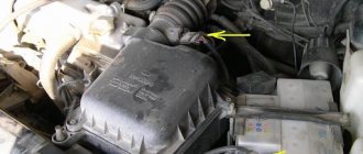
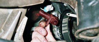
The mass air flow sensor, abbreviated as MAF, is an important organ in the injection system. It is also called a consumable. The main task of the unit is to calculate the required amount of fresh air that enters the cylinders during engine operation. A sensor is installed in the air duct and measures the temperature and amount of incoming air. Under the hood it can be found inside the intake tract.
VAZ air flow sensor pinout. Checking and repairing the air flow sensor
Based on the signal from the mass air flow sensor (MAF), the cyclic filling of the cylinder is calculated, which is ultimately converted into the duration of the injector opening pulse. If it does not work correctly, the car consumes more gasoline than necessary. Such a sensor is installed on the second path, immediately behind the air filter and connected to the electrical system, which is controlled by a six-pin block of wires.
There are quite a few different types of mass air flow sensors: mechanical, ultrasonic, hot-wire and some others.
In this case, we will consider the design of the HFM-5 hot-wire sensor from Bosch, which is most often installed on VAZ cars. The sensor's sensitive element is a thin film on which several temperature sensors and a heating resistor are located. In the middle of the film there is a heating area, the degree of heating of which is controlled using a temperature sensor.
On the surface of the film, on the side of the air flow and on the opposite side, two more thermal sensors are located symmetrically, which record the same temperature in the absence of air flow. In the presence of air flow, the first sensor is cooled, and the temperature of the second remains unchanged, due to the heating of the air flow in the heater zone. The differential signal of both sensors is proportional to the mass of passing air.
The sensor's electronic circuit converts this signal into a constant voltage proportional to the air mass. This design is called Hot Film (HFM), its advantages include high measurement accuracy and the ability to record reverse air flow, but its disadvantages include low reliability in conditions of contamination and moisture.
To measure the amount of air that enters the engine means to determine the engine load. When the driver presses the gas pedal, the throttle valve opens and the amount of intake air increases. At the same time, we say that the load has increased. When you release the pedal, the load drops. It's quite simple. However, this is only at first glance. If we take into account the fact that in real driving conditions the engine often changes operating modes and the incoming air in the intake system participates in several gas-dynamic processes, then the problem of measuring the air in the system is not so simple.
In older systems (ECU January-4 and GM-ISFI-2S), other hot-wire mass flow sensors were used, the sensitive elements of which were made in the form of threads. Such sensors are called Hot Wire MAF Sensor. The output signal of these sensors was frequency, that is, depending on the air flow, it was not the voltage that changed, but the frequency of the output pulses. The sensors were less accurate and did not allow registering reverse flow, but these shortcomings were offset by very high reliability.
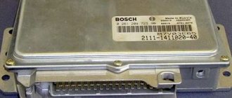
Several types of mass air flow sensors were installed on VAZ cars: GM, BOSCH, SIEMENS and Russian-made. In 1999-2004 Two types of sensors were installed on VAZ cars: 0 280 218-037 and 0 280 218-004. These sensors produce different output voltage (calibration) parameters at the same air flow rate and interchangeability (or rather, replacing 004 with 037) is only possible with the replacement of calibration tables in the firmware. The same applies to the new sensor 116, which has been installed as standard since the beginning of 2005.
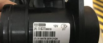
The sensor is supplied only assembled, with a code and marked with a green circle.
On some classic cars, together with the January 7.2 ECU, Siemens-VDO sensors (5WK97014. AVTEL) were used:
They differ in calibration (from zero volts) and connection diagram.
We check the mass air flow sensor on a VAZ-2110 with a multimeter
The sensor block, the first wire may not be there - this is normal.
To do this, we need to understand the pinout and the sensor connection diagram. As you can see, the block has only five wires:
- + 12 Volt.
- + 5 Volts.
- Total ground (green wire).
- Air temperature output signal.
- Air flow signal output (yellow wire).
Electrical diagram for connecting the mass air flow sensor.
The pinout may differ in different firmware versions and on different sensors. Everything is clear with the first two contacts - take a multimeter and check the presence of voltage when the ignition is on. If there is no signal, we look for the cause either in broken wires or in poor contact. Now we check the main indicator - the accuracy and magnitude of the air flow signal. By the way, this can be checked without a multimeter, using the on-board computer, if one is installed:
- We go to the menu, look for sensor parameters.
- Find the voltage Udmrv.
- The rating for all of the above modifications is from 0.996 to 1.01 V.
The platinum thread gets tired over time and distorts the impulse upward. A change of even one hundredth of a Volt is unacceptable. If the computer is not installed, we use a multimeter. We check the voltage between 3 and 5 (minus) contacts , setting the measurement limits on the multimeter to 2 V. Turn on the ignition, but do not start the engine.
Cars with injection engines are equipped with a mass air flow sensor (MAF). The sensor's task is to control the amount of outside air to create an air-fuel mixture entering the engine.
Connection diagram for air flow sensor 2114
A common cause of incorrect operation of the mass air flow sensor is the failure of electronic components, which increases the sensor’s response time to changes in air flow. A working sensor monitors changes at a speed of 0.5 ms, and if it breaks down, the response time increases by 20-30 times. The defect is detected only by recording the operation graph with an oscilloscope. Such a sensor cannot be repaired; it must be replaced with a new one.
Causes of malfunction
Common to most domestic cars, the reason why the VAZ 2114 air flow sensor breaks is hidden in the crankcase ventilation system. It has two circuits that ensure operation with the throttle valve open or closed. If the throttle is buried, crankcase gases are discharged along the line (d=1.5 mm) into the space available behind it. A certain percentage of these gases accumulates in the idle line, where it comes into contact with the film-coated MAF resistor. It is also sensitive to fluctuations in the gas mixture in the intake system. The resin settles on the surface of the resistor, and the sensor begins to “lie.” Because of this, the idle air control sticks, and it begins to jam when starting the engine.
We recommend: High-quality motorcycle tires in the Inwheel online store
Checking the air sensor yourself
When a malfunction of the mass air flow sensor occurs, the air-fuel mixture becomes over-rich or lean, which immediately affects the operation of the engine and may ultimately result in engine failure.
Symptoms of a malfunctioning mass air flow sensor:
The easiest way to check the mass air flow sensor on a VAZ 2114 is to disconnect the plug. If there is no signal, the engine control unit goes into emergency operation mode, determining the approximate air volume based on the throttle position. At the same time, fuel consumption increases slightly - for the VAZ 2114 it reaches 10-12 liters per 100 km. A characteristic feature is the increase in idle speed to 1500 rpm. But when using a January 7.2 or Bosch M7.9.7 controller, the idle speed does not increase due to the software features.
The normal voltage at the output of the new sensor is 0.996 - 1.01 Volts. During operation, it gradually changes and, as a rule, increases. The greater the value of this voltage, the greater the wear of the mass air flow sensor.
Here is the reference voltage in volts:
The measurement is made between the yellow and green wires. Voltage values can be displayed on the screen of some on-board computers (menu voltage from sensors, U Mass air flow sensor).
Important: the limits and fluctuations of the output voltage in at least 30% of cases for a faulty sensor will be NORMAL and will not cause the “Check” icon on the panel. That is, voltage measurements are not very informative, but the rate that it will produce in kilograms of air will correspond to the movement not where it actually is, and the ECU will interfere with the mixture based on it - hence the extra consumption!
You need to check the sensor at a service center, preferably with a proprietary scanner, which itself indicates by blinking if there is a imbalance in some parameter (in this case, air flow in kilograms), comparing it with the reference values stored in its memory.
Types of mass air flow sensors, their design features and operating principle
Three types of VU meters are most widespread:
- Wire or thread.
- Film.
- Volumetric.
In the first two, the operating principle is based on obtaining information about the mass of the air flow by measuring its temperature. The latter may involve two accounting options:
- By changing the position of the slider, driven by a special blade, which is affected by the air flow passing through the device. Considering the presence of rubbing mechanisms, the level of reliability of such structures is quite low. This was the main reason for the refusal of car manufacturers from sensors of this type. For reference, here is a simplified example of the design of a volumetric flow meter.
Volumetric air flow sensor device - By counting Karman vortices. They are formed if a laminar air flow washes over an obstacle whose edges are quite sharp. The frequency of the vortices breaking off from them is directly related to the speed of air flow passing through the device.
Vortex sensor design (widely used by Mitsubishi Motors)
Designations:
- A – pressure measurement sensor to record the passage of the vortex. That is, the frequency of pressure and vortex formation will be the same, which makes it possible to measure the flow of the air mixture. At the output, using an ADC, the analog signal is converted to digital and transmitted to the ECU.
- B - special tubes that form an air flow similar in properties to laminar.
- C – bypass air ducts.
- D – column with sharp edges on which Karman vortices are formed.
- E – holes used to measure pressure.
- F – direction of air flow.
Wire sensors
Until recently, thread mass air flow sensor was the most common type of sensor installed on domestic cars of the GAZ and VAZ model range. An example of a wire flow meter design is shown below.
Design of volumetric meter IVKSH 407282.000
Designations:
- A – Electronic board.
- B – Connector for connecting the mass air flow sensor to the computer.
- C – CO adjustment.
- D – Flow meter housing.
- E – Ring.
- F – Platinum wire.
- G – Resistor for temperature compensation.
- N – Ring holder.
- I – Electronic board casing.
Operating principle and example of a functional diagram of a filament VU meter.
Having understood the design of the device, let's move on to the principle of its operation, it is based on the hot-wire method, in which a thermistor (RT), heated by the current passing through it, is placed in the air flow. Under its influence, the heat transfer changes, and, accordingly, the resistance RT, which makes it possible to calculate the volumetric flow rate of the air mixture? using King's equation:
where I is the current passing through RT and heating it to temperature T1. In this case, T2 is the ambient temperature, and K1 and K2 are constant coefficients.
Based on the above formula, you can derive the volumetric air flow rate:
An example of a functional diagram with bridge connection of thermoelements is shown below.
Typical functional diagram of a wire mass air flow sensor
Designations:
- Q - measured air flow.
- U – signal amplifier.
- RT - thermal resistance wire, usually made of platinum or tungsten filament, the thickness of which is in the range of 5.0-20.0 microns.
- RR – temperature compensator.
- R1-R3 are ordinary resistances.
When the flow velocity is close to zero, the RT is heated to a certain temperature by the current passing through it, which allows the bridge to be kept in equilibrium. As soon as the flow of the air mixture increases, the thermistor begins to cool, which leads to a change in its internal resistance, and, as a result, an imbalance in the bridge circuit. As a result of this process, a current is generated at the output of the amplifier unit, which partially passes through the temperature compensator, which leads to the release of heat and makes it possible to compensate for its loss from the flow of the air mixture and restores the balance of the bridge.
The described process allows you to calculate the flow rate of the air mixture based on the amount of current passing through the bridge. In order for the signal to be perceived by the ECU, it is converted into a digital or analog format. The first allows you to determine the flow rate by the frequency of the output voltage, the second - by its level.
This implementation has a significant drawback - a high temperature error, so many manufacturers add a thermistor similar to the main one to the design, but do not expose it to air flow.
During operation, dust or dirt deposits may accumulate on the wire thermistor; to prevent this, this element is subjected to short-term high-temperature heating. It is performed after the internal combustion engine is turned off.
Film air meters
A film MAF works on the same principle as a filament one. The main differences lie in the design. In particular, silicon crystal is used instead of platinum filament resistance wire. It is coated with several layers of platinum plating, each of which plays a specific functional role, namely:
- Temperature sensor.
- Thermal resistances (usually there are two of them).
- Heating (compensation) resistor.
Replacing the sensor - instructions
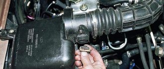
Using a screwdriver, unscrew the clamp of the air intake corrugation at the sensor outlet, pull it off and carefully inspect the internal surfaces of the sensor itself and the corrugation. These surfaces must be dry and clean; traces of condensation and oil are unacceptable. If the air filter is changed rarely, then dirt getting on the sensitive element of the sensor is the most common cause of its breakdown in VAZ cars.
There may be oil in the mass air flow sensor as a result of an increased oil level in the engine crankcase, or the oil sump of the crankcase ventilation system is clogged.
Next, unscrew the 2 screws of the sensor with a 10mm wrench and remove it from the air filter housing. There should be a rubber sealing ring on its front part (at the entrance edge). It prevents unfiltered air from being sucked into the intake tract through the sensor.
If the ring is out of place and stuck somewhere in the air filter housing, then there will be a thin layer of dust on the inlet mesh of the sensor itself. This is the second reason that destroys the mass air flow sensor ahead of time.
Correct assembly should take place in the following sequence: put a sealing rubber band on the sensor, check the sealing skirt, then insert everything together into the filter housing.
This concludes the visual check of the mass air flow sensor at home. You can check its operation 100% only with the help of special equipment in a car service center. For example, using a technique for assessing the oscillogram when the throttle is sharply opened to the cutoff mode (a motor tester is needed), or assessing the oscillogram when the ignition is turned on.
Resuscitation of a damaged air flow sensor is successful in no more than 5% of cases. In extreme cases, you can rinse with ethereal liquid to clean matrices and optics. It will evaporate without a trace. After making sure that there is no more dust or debris in the device, you can dry it thoroughly and put it back in place. Sometimes after such a simple procedure the device will work.
On most foreign cars, a mass air flow sensor was installed until 2000; subsequent generations of models began to be equipped with a pressure controller. Replacing a non-working sensor is simple and can be done on your own without any problems, you just need to buy a mass air flow sensor that matches the ECU firmware version. Its price is around 3,000 rubles, depending on the manufacturer.
Symptoms of a problem
A non-working VAZ 2114 mass air flow sensor leads to the appearance of a number of symptoms in the behavior of the injection engine. The malfunction appears gradually, starting with an increase in fuel consumption and floating speed, ultimately destabilizing engine operation.
From personal experience using a front-wheel drive car as an example, I can say that I encountered the following problem: first the injector icon came on, then the speed began to fluctuate greatly and fuel consumption almost doubled.
You can calculate a non-working VAZ 2114 air sensor using the following criteria:
- failures when idling and under load;
- The internal combustion engine stalls when trying to change gear;
- decreased dynamics, the car accelerates slowly;
- fuel consumption increased;
- engine power has dropped;
- Badly ;
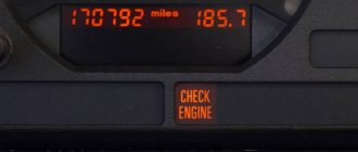
- The Check Engine signal appears.
If the mass air flow sensor is already dead, the Check Engine light may not come on. Then the malfunction can be determined by the error generated by the on-board computer. Diagnostics of the MAF signal level will also help. A low level may indicate the following:
- There is no MAF connection;
- malfunction in the sensor connection circuit (break);
- the ground in the connection circuit is broken or oxidized;
- the signal wires are broken or incorrectly connected, perhaps they are short-circuited;
- engine control unit malfunction;
- DMRV does not work.
If you notice the above signs, do not rush to buy a new sensor. It is by no means the cheapest and will cost 1500-4000 rubles. First of all, make sure that this is the reason. You can check and clean the old one at a service center or yourself if you have the necessary equipment.
DMRV error code
The following errors may indicate a malfunction in the operation of the mass air flow sensor:
- P0100 - damage to the electrical circuit connecting the sensor. To eliminate the breakdown, you need to check the wiring for integrity, since accidental disconnection of the connector or damage to the electrical contacts is possible.
- P0102 - the vehicle control unit began to receive a low signal, which was recorded at the input of the mass air flow sensor power line. To eliminate the cause of the breakdown, it is necessary to check the electrical wiring and the insulating layer of the cable; oxidation of the contacts of the wiring connector (the so-called chips) is possible.
- P0103 - critically high signal detected at the input of the mass air flow sensor power line. If the cause of the malfunction is not the wiring, then a visual inspection and cleaning of the flow meter will be required or it will have to be replaced with a new one.
Lada 2108 Project ArhStyle › Logbook › Replacing the air flow sensor VAZ 037
I didn’t like the sluggish response to the gas pedal - I connected my brain to the laptop, installed a good OpenDiag program for diagnostics and started analyzing... A lean mixture when you sharply press the gas pedal, then it is corrected by DC and a drop in speed if you quickly release the gas - misleading readings of the amount of air, the air is calculated by the mass air flow sensor, in its absence the table of mass air flow sensor / revolutions, the temperature is constant.
The culprit turned out to be the mass air flow sensor, I will describe one well-known method of checking - I’ll even call it “folk”) Checking the mass air flow sensor with a multimeter. This method works on Bosch sensors with catalog numbers: 0 280 218 004, 0 280 218 037, 0 280 218 116. Turn on the tester in the DC voltage measurement mode, set the measurement limit to 2 Volts.
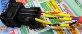
DMRV pinout
: Yellow (closest to the windshield) - mass air flow sensor signal input; Gray-white—sensor supply voltage output; Green — sensor grounding output; Pink-black - to the main relay. The wire colors may change, but the pin locations remain the same.
Correct connection of the tester to the mass air flow sensor
— turn on the ignition, but do not start the engine. We connect the multimeter with the red probe to the yellow mass flow sensor, and the black one to the green one (to ground). Thus, we measure the voltage between the specified terminals. The tester probes allow you to penetrate through the rubber seals of the connector, along the specified wires, without disturbing their insulation.
The output voltage of the new sensor is 0.996…1.01 Volts. During operation, it gradually changes and, as a rule, increases. The greater the value of this voltage, the greater the wear of the mass air flow sensor. Mass air flow sensor voltage: 1.01…1.02 - good condition of the sensor. 1.02...1.03 - not a bad condition. 1.03…1.04 - the life of the mass air flow sensor is coming to an end. 1.04...1.05 - a dying state, if there are no negative symptoms, then we continue to exploit it. 1.05...and higher - it’s time to replace the mass air flow sensor.
By the way, the same readings can be obtained without a tester, using the on-board computer (group of parameters “voltage from sensors”, Udmrv)
My readings were 1.10 V xDDD, I cleaned it, it became 1.07 V - where is the wheel, but to the side of the road) Cleaning did not help, I paid 2500 rubles for a new original Bosh 037 sensor, sensor 116 is even more expensive. If it’s really hard to find this sensor, you can replace it with 116, but with subsequent recording of the calibration table in the ECU.
Additionally: Using a shaped screwdriver, unscrew the clamp of the air intake corrugation at the sensor outlet, pull it off, and carefully inspect the internal surfaces of the sensor itself and the corrugation. These surfaces must be dry and clean; traces of condensation and oil are unacceptable. If the air filter is changed rarely, then dirt getting on the sensitive element of the sensor is the most common cause of its failure. There may be oil in the mass air flow sensor as a result of an increased oil level in the engine crankcase, or the oil sump of the crankcase ventilation system is clogged. I noticed a couple of drops of oil on mine, most likely they remained down to the capital - I cleaned it with a napkin, then blew it out and cleaned it with a solvent under pressure)
There is an option to clean it - in any case, it won’t get any worse, a couple of videos on this topic:
Source
Testing and diagnostic methods
Shutdown
This method involves starting the motor with the sensor removed - we need to disconnect its connector. When turned off, the controller starts emergency mode, and new portions of the mixture are calculated based on the position of the damper. We need to drive a little, the speed should be above 1500 rpm. If the car behaves more dynamically without a mass air flow sensor, then the diagnosis is complete - it’s time to change the consumable.
Checking with a multimeter
This test requires that you have skills in using a multimeter (tester). The method is suitable for almost all VAZ models, including 2110. We need to take a multimeter and set it to a mode that measures constant voltage, which is usually designated DCV or only V. To work with the mass air flow sensor, you need to understand its pinout, it is as follows:
- Yellow, closest to the windshield, supplies current to the signal input;
- Green indicates ground;
- The pink or red-black wire comes from the main relay;
- The white-gray wire is responsible for the voltage output.
Depending on the model, the colors may be different, but the location does not change. Here you will have to deal with a specific model. But once you find the input signal wiring (closer to the windshield) and grounding, you can do it without instructions. The wiring is clear, now you need to turn on the ignition without starting the engine. The tester sets a limit of 2 Volts. The black probe of the tester is connected to the green ground wire of the air flow sensor, and the red one is connected to the yellow one. The measurement takes place between two terminals. The probes must be inserted carefully; an additional needle is not required, since the probes can be freely inserted along the wires without damaging the insulation.
We look at the tester display. If the consumable is new, then there we will see a voltage indicator of 1.01. Over time, the indicator increases as the resistors wear out (the resistance drops). The larger the number, the greater the wear of the sensitive element:
- In good condition, the indicator will be 1.01… 1.02;
- With “normal” - 1.02... 1.03;
- The sensor will soon stop working – 1.03… 1.04;
- The dying state of the flow meter is accompanied by an indicator of 1.04… 1.05;
- Replacement of the unit is required when the reading is 1.05 or higher.
What does a faulty air flow sensor cause?
Operating an engine with an inoperative/faulty flow meter causes detonation of the fuel mixture in the combustion chamber. This affects the operation of the crank mechanism (crank mechanism) and destroys the piston surface, which can cause a “wedge” in the engine.
What indications should a working mass air flow sensor give?
The voltage of the analog-to-digital converter (ADC) of the flow meter when the engine is not running should be 0.996 V. Indicators of 1.016 and 1.025 V are acceptable, but if they reach more than 1.035 volts, it means that the sensing element of the mass air flow sensor is clogged.
We recommend: Choosing a car alarm
It is important to know
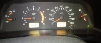
To accurately determine the degree of deviation of the operating flow meter values from normal values, it is necessary to evaluate the engine operation at different speeds.
For example, for an injection 1.5-liter VAZ 2111 engine, if it is in good condition, at idle (860–920 rpm) the correct readings are 9.5–10 kg/hour, and at 2 thousand rpm - 19 –21 kg/hour. If the flow meter at 2 thousand rpm shows about 17–18 kg, then the car will drive stably. If the values are from 22 to 24 kg/hour, then the vehicle will move steadily, but the fuel consumption per 100 km will be approximately 10–11 liters. In addition, the car will have difficulty starting in cold weather due to fuel overflow when the engine warms up.
Cleaning instructions
As practice shows, cleaning the mass air flow sensor is one of the most effective methods of restoring the functionality of the controller. Therefore, if the sensor breaks down, it is not necessary to change it, especially since such a pleasure today is not cheap. This procedure is necessary because over time it becomes dirty and shows other parameters.
So, how to clean the mass air flow sensor at home with your own hands:
- You will need a Phillips head screwdriver; use it to loosen the clamp securing the line from the air intake.
- Next, dismantle the corrugation and visually assess the condition of the system. You may see condensation or traces of engine fluid under the corrugation.
- Carefully inspect the inside of the controller. If everything is normal with the system, then there will be no traces of leaks or contamination. As practice shows, the sensitive element often breaks precisely due to an excess of contamination. In order not to avoid problems of this kind in the future, it is necessary to periodically replace the air filter. This procedure is carried out in accordance with technical regulations. Engine fluid may enter the controller as a result of an increased level of consumables in the crankcase. Accordingly, this occurs as a result of a clogged oil separator in the ventilation system.
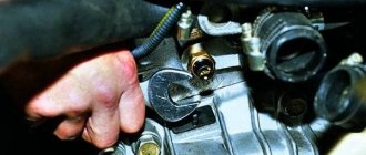
- The regulator itself is fixed with two bolts on the line. The removal procedure is carried out using an open-end wrench. At this stage, if you are sure that the device has failed, you can replace it.
- You can see the entrance on which there will be a sealing rubber band designed to protect the device from the suction of dirty air flow. If you do not have a seal, it may have caught on the filter element. Accordingly, this will lead to the regulator input grid being contaminated.
- Clean the mesh using available materials. To do this, you can use a regular toothpick or toothbrush. After cleaning, the seal can be put back and the regulator can be put back in place.
What is the difference between sensors 037 and 116?
How can the regulators of these models differ from each other and is it possible to install 116 instead of 037? There are differences between these controllers, and the point is not in the MAF pinout. After all, if these models were the same, what would be the point of giving them different names?
So, how do the controllers differ from each other and is it possible to install model 116 instead of 037:
- The first difference that can be guessed based on the technical characteristics is that the 037 model can produce data with an error during operation. Of course, an error of 2.5% is not critical, but it does exist.
- Device 037 is intended for installation in VAZ 2111, 2112, 2123, 21214 cars, which are equipped with controllers M 1.5.4, January 5.1-5.1.3, etc.
- As for model 116, its use is relevant on Ladas 21114, 21124, 21214. Installation of this device is allowed on Kalina and Priora. Installation of the device is allowed on cars equipped with M 7.9.7 and January 7.2 controllers.
If you encounter a problem with the device not working, then when replacing it you need to install the same model that has already been installed. But it is worth considering that 037 is not a common option like 116, so it is more difficult to find. The latter, in turn, is more common, and its cost is lower.
Replacement is allowed, but experts do not recommend this. This is because these devices differ in their calibration, so in case of replacement, you will have to change the parameters of the control unit. And you can only get into the “brains” of a car if you understand what needs to be done and have minimal experience.
What's the result?
As you can see, if there are signs of problems and the first symptoms of the DMVR VAZ 2114 or another car appear, you should check the device as soon as possible for possible breakdown. In this case, you can quickly diagnose the air flow sensor with a multimeter in a regular garage.
We also recommend reading the article about what a car engine knock sensor is. From this article you will learn about the purpose, design, as well as signs of malfunction or malfunction of the engine knock sensor. Based on the readings obtained from the device, it is possible to determine the malfunction (if a breakdown is confirmed) or to exclude the mass air flow sensor from the list of possible problem elements. One way or another, it is important to understand that this sensor is actively involved in mixture formation and affects the operation of the engine as a whole.
For this reason, it is necessary to perform regular checks of the ECM, scan for errors, and also pay attention to any failures and symptoms of malfunctions of the sensors of the electronic engine control system (TSP, DPKV, etc.).
Sources
- https://carfrance.ru/proveryaem-dmrv-na-vaz-2110-multimetrom-svoimi-rukami/
- https://labavto.com/vaz/2114/dmrv-diagnostika-i-chistka/
- https://remontvazov.com/dmrv-vaz-2114
- https://NaDomkrat.ru/ustroistvo-avtomobiley/elektrooborudovaniye/datchik-massovogo-rashoda-vozduha-vaz-2114
- https://avtozam.com/elektronika/sensor/dmrv-priznak-neispravnosti/
- https://KrutiMotor.ru/dmrv-vaz-2114-proverka/