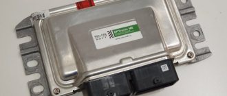
There is such a cunning electronics unit in the Berry-Kalinaya car, it’s called “Norma”. "How are you?" "Norm!"
According to the plan of smart people, it should make the already difficult life of car owners easier. Which is what he does successfully. Scientifically, this block module is called quite cleverly - “SDU electrical package “NORMA”, which in translation will be “remote control system”. It looks very brutal - a black slender body, contours that cut off all attempts to ask questions. It has 25 legs, just short of a centipede).
And his legs are not just any kind, but all filled with deep sacred meaning, which, despite all its sacredness, was nevertheless successfully documented and summarized in a single table:
And in light of what I wrote the day before, I actually really need this sign. Because it has a leg “13”, which will do the job of opening the trunk for me when an impulse is applied there with a potential close to “0”, ground, mass. And this impulse will push this diagram, which I hastily drew on a napkin while I was sitting in the dining room and eating cabbage soup, washing it down with compote during lunch:
In general, this is another small step towards a trunk opener...
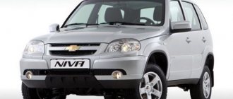
Auto manufacturers today use many technological solutions to ensure more comfortable driving. One of such devices is CBKE. What is the central unit of body electronics Kalina 2 needed for, what functions does it perform and what malfunctions are typical for it - read in this article.
Purpose and characteristics of TsBKE
The central unit of body electronics Kalina 2 controls:
- alarm system;
- windshield wipers;
- heated windshield and rear windows;
- heated side mirrors;
- lighting system;
- direction indicators;
- central locking;
- trunk opening drive;
- electric windows;
- heated front seats;
- electric side mirrors.
When the alarm is turned on, an automatic check occurs, accompanied by a short flashing of the direction indicators. In security mode, the immobilizer light on the instrument cluster blinks. The security mode is disarmed by pressing the remote control button.
The central electronic unit automatically turns on the windshield wipers if:
- a signal was received from the rain sensor;
- sensitivity regulator in position from 1 to 4;
- The wiper switch is in the intermittent position.
If a malfunction is detected in the operation of the windshield wiper, TsBKE Kalina 2 switches it from automatic to manual control mode. When the windshield heating function is turned on, the body electronics monitor the on-board voltage and limit the heating duration to 6 minutes. When the voltage drops below 12 V, the CBKE switches off the heating mode.
When the voltage drops to 9.6 V, the central unit limits the operation of the rear window and side mirror heaters. This prevents the engine from going into emergency mode. When the voltage is restored to a level of 10.8 Volts, the heaters turn on automatically.
The driver is also assisted by body electronics when working with the lighting system. When the engine starts, the daytime running lights turn on, and when the engine stops, they turn off automatically. The low beam headlights and side lights turn on when a signal is received from the light and rain sensor. At the same time, the daytime running lights turn off. If during automatic diagnostics a malfunction is detected, the absence of a signal from the light sensor, then the TsBKE turns on the low beam and dimensions.
Description of CBKE
Unlike the first Kalin models, the second versions and Luxury equipment use an electrical package control unit instead of traditional relays to control the electronics. This device combines many functions, we suggest you familiarize yourself with them in more detail.
Connection diagram of elements and outputs of the CBEK
Functions
The electrical package control unit is designed to perform the following functions:
- Alarm. If the car's anti-theft system detects a break-in attempt, thanks to the CBKE, it will transmit information about this to the car owner's control panel.
- Windshield wiper system control. Moreover, we are talking about both manual and automatic control (if the car is equipped with an electrical package control unit marked 21900-3840080-20).
- The device performs the function of controlling the windshield and rear window heating systems. This unit also controls the heating elements of the side rear-view mirrors.
- The electrical control unit also monitors the performance of the optics, both in manual and automatic control modes. In particular, we are talking about low-beam headlamps, side lights, and DRLs.
- Separately, we should highlight the function of ensuring the functionality of the high-range lighting.
- Turning lights, as well as light signaling.
- Vehicle interior lighting.
- The device monitors the performance and energy saving of devices belonging to the category of internal lighting of the car.
- Monitoring the state of the central lock, as well as performing the functions of locking and unlocking the locks themselves from the key, from buttons installed in the car interior, as well as in the doors.
- Another option is to open the luggage compartment lid using a button installed in the cabin.
- An equally important function is the control of electric drives, in particular, we are talking about power windows, as well as side rear-view mirrors.
- Heating system for driver and passenger seats.
- Luggage compartment lighting unit (video author - Vladimir Kostyuchenkov).
Typical faults
If the electrical package control unit fails for some reason, this can lead to the following problems:
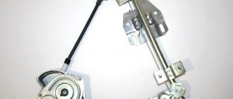
- Failure to operate power windows. Of course, before disassembling the control module, you should make sure that the window regulators do not work precisely because of it. It would be logical to first check the safety element, as well as the lift control unit, which is built into the driver's door. In practice, it often happens that the cause of power window failure is poor wiring contact on the unit itself.
- The optics stopped working - low beam, turn signals, etc. In this case, the safety elements, light sources and steering switch are first checked. There is a possibility that the reason lies in a broken contact directly on the switch; if this is the case, then they should be re-soldered. If the reason is that the unit is not working, it will need to be dismantled and disassembled in order to find the burnt-out element and re-solder it. If soldering does not help solve the problem, the device will have to be replaced.
- Some of the equipment has stopped working, while the devices, as at first glance may seem, are in no way connected with each other. The fact is that the module itself includes many elements and controllers, each of them is responsible for performing certain functions. If two or more controllers fail at once, it can cause serious damage. For example, the optics, heated rear and front windows, the trunk door and the window regulator will immediately refuse to work. It is necessary to locate the failed controller and replace it by re-soldering.
- A fairly common problem that can occur is a break in the wiring of the unit. It is installed in a virtually inaccessible place, but if electrical work is being done, for example, installing an anti-theft system, then most likely the car owner will encounter a TsBKE. And if the wiring is damaged during the work, of course, this will affect the functioning of the device and, accordingly, the performance of certain functions.
- Oxidation of contacts on module connectors. If you encounter such a problem, we recommend paying attention to the humidity in the cabin. Often, oxidation at the outlets occurs precisely as a result of high humidity. The contacts can be cleaned, this is not a problem, but the problem of humidity must be addressed, since otherwise it can lead to failure of the microcircuit as a whole.
- Board failure. The most terrible problem for the car owner, because because of this the device simply will not be able to work normally. Accordingly, it will need to be replaced, and this, in turn, costs a lot of money (author - Alexander Fisher).
Possible breakdowns of body electronics and their elimination
CBKE allows you to free the driver from routine work and focus his attention on driving and managing the traffic situation. Despite this undeniable advantage, persistent failures of some nodes often occur. One of the most common malfunctions is the failure of turn signals and hazard warning lights. This most often manifests itself in the fact that the lamps simply burn continuously on the left side of the car. Before you begin repairing the TsBKE, you need to make sure that the lights are not burnt out, their contacts are not oxidized, the emergency stop button is working, and the wires are not charred.
The reason for the failure of the power windows may be a breakdown of the electronic control unit. There are other options: problems with the window regulator built into the driver's door, poor wire contact, incorrect installation of limiters.
You can repair the electronic unit yourself. To do this, you need to remove it from its regular place, open the cover and carefully inspect the circuit for the presence of soot or melted parts of the controllers. If you find obvious defects in the controllers, you should replace them and reinstall the software through a special connector on the electronic unit. In order to correctly replace burnt-out components, you need to have a “pinout” - information about connectors, wiring, input and output ports, various adapters and plugs.
Where is the Priora comfort block located?
To gain access to the product, you will need to unscrew the protective plastic walls of the car's center console. They are located on the left side of the front passenger seat and on the right of the gas pedal, on the driver's side. The device itself is located above the control unit. In order to remove the device you will need a 10 mm wrench and a Phillips screwdriver.
Pinout of the Priora comfort block
The main, important elements of the device are:
- The so-called control drivers. Each driver is responsible for a set of specific functions.
- Transponder receiver.
- Relay control.
- Transceiver. Communicates with the module installed in the door.
- 2 connectors. The first is responsible for supplying power, the second for transmitting the necessary technical information.
Click to enlarge
To ensure proper operation of all elements connected to the comfort unit connectors, it is necessary to study the correct pinout (numbered diagram for connecting wires to contacts). The design of the comfort block for the Priora, when studied in detail, is not particularly difficult.
Replacement instructions
First you need to remove the instrument panel on the center console, then remove the lower part of the dashboard trim under the steering wheel. Now you need to unscrew the fuse box and turn it so that it takes a horizontal position. You need to stick your hand into the freed space until it comes into contact with the shelf on which the TsBKE is installed.
By unscrewing the fixing bolt, you can pull up the control unit and, after disconnecting the two electrical connectors, carefully pull it out. After dismantling the device, it is repaired or replaced with a new one. Installation of the device is carried out strictly in reverse order.
The introduction of modern technologies in the field of control of electronic equipment of a car makes the driver’s work easier, frees him from unnecessary loads and reduces the likelihood of road accidents. Along with the positive aspects of the implementation of CBKE, there are also a number of disadvantages associated with the unreliability of some nodes. Factory engineers are working hard on this problem. According to recent reviews from car enthusiasts, the number of malfunctions of the central unit of body electronics and the frequency of their occurrence are decreasing.
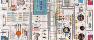
No work on modifying the electrical system or connecting additional electrical equipment can be carried out without electrical circuits. Next you will find a set of electrical diagrams for VAZ 1117, 1118 and 1119.
General diagram of electrical equipment of VAZ 1118
1 — block headlight; 2 — windshield wiper gear motor; 3 - generator; 4 - battery; 5 - starter; 6 — sound signal; 7 — hood open sensor; 8 — power window switch for the right front door; 9 — motor-reducer for window lifter of the right front door; 10 — electric pump for windshield washer; 11 — connecting blocks of wires for connecting the right (front) speaker of the audio system; 12 — electric drive for locking the lock of the right front door with an open door sensor; 13 — ambient air temperature sensor; 14 — connecting block of the wiring harness for connection to the engine control system harness; 15 — electric drive for locking the left front door lock (with an open door sensor and a central locking switch); 16 — sensor of insufficient brake fluid level; 17 — connecting blocks of wires for connecting the left (front) speaker of the audio system; 18 — right front door power window switch (installed on the driver’s door); 19 — left front door power window switch; 20 — central locking switch; 21 — motor-reducer for window lifter of the right front door; 22 — remote control unit; 23 — immobilizer control unit (APS-6); 24 — mounting block; 25 — instrument panel; 26 — right side turn signal; 27 — glove box lighting lamp; 28 — switch for the glove compartment lighting lamp; 29 — brake signal switch; 30 — ignition switch (lock); 31 — lighting control unit; 32 — steering column switches; 33 — left side direction indicator; 34 — connecting blocks of wires for connecting the left (rear) speaker of the audio system; 35 — electric drive for locking the left (rear) door with an open door sensor; 36 — electric heater fan; 37 — additional heater resistor; 38 — heater switch; 39 — alarm switch; 40 — reverse lock solenoid switch; 41 — rear window heating switch; 42 — connecting blocks of wires for connecting the right (rear) speaker of the audio system; 43 — electric drive for locking the right rear door lock (with a door open sensor); 44 — fuel module of the engine control system; 45 — reverse light switch; 46 — parking brake warning lamp switch; 47 — cigarette lighter; 48 — reverse lock solenoid; 49 — connecting blocks of wires for connecting the head unit of the audio system; 50 — backlight lamps on the trim of the center console of the instrument panel; 51 — electric power steering control unit; 52 — interior lamp; 53 — rear light; 54 — block for connecting the electric drive for locking the trunk lid lock*; 55 — luggage compartment lid open sensor; 56 — license plate lights; 57 — additional brake light; 58 — rear window heating element; 59 — luggage compartment lighting lamp.
Basket
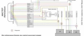
Double-glazed window control unit “Norma” 1118 – 6512010 for VAZ 11183 “Kalina”
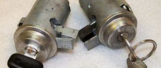
©Aktuator On cars of the Kalina family, 2 types of non-interchangeable (by wiring) glass control controller 1118 - 6512010 and 11180 - 3763040 can be installed. 1118 – 6512010 has one 25-pin connection connector, 1118 – 3763040 (1118 – 3763040 – 10) – two connectors.
Remote control system for double-glazed windows “norm” on a VAZ 11183, Kalina. Controls power windows and central door locking. When the connector is removed, the engine does not start; the device performs some of the anti-theft functions.
Connection
| № | Wire color | Purpose, addressing |
| 1 |
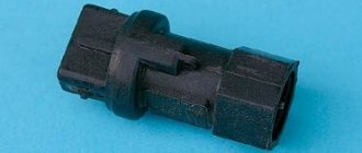
* A regular shock sensor from any alarm system (Alligator, Saturn, Clifford, APS) is suitable.
+ 12 V connect to pin 12; body – on the 6th; We connect the signal wire (a ground appears on it at the moment of activity) to the 1st contact.
During normal arming, Kalina now reacts to an impact on the body (it sounds a horn and blinks turn signals). Similarly, instead of a shock sensor, you can connect a volume sensor (for example, single-level MMS‑1).
You can also connect a pager: + 12 V of the pager transmitter on pin 12, minus on pin 21.
Double-glazed window control unit 1118 – 3763040 (- 10 ) for VAZ 11183 “Kalina”
| External shock or volume sensor input (Not used)* | ||
| 2 | Pink/Black | To the door lock switch in the switch block |
| 3 | Brown/Green | K-Line. To Kl. 71 ECM, Cl. 18 APS‑6 |
| 4 | Brown | Connects to ground when the driver's door is closed |
| 5 | Grey | To rear window heating element |
| 6 | Black | Weight |
| 7 | Pink/White | To the door lock switch in the switch block |
| 8 | Yellow/Blue | In the instrument cluster, to the APS-6 indicator |
| 9 | Black/White | Connects to ground when opening the hood. C VK engine compartment lamp |
| 10 | Two White/Red | Connects to ground when opening the rear doors |
| 11 | Brown/Red | Connects to ground when opening the right front door |
| 12 | Output 12 V power supply for external sensor (Not used)* | |
| 13 | Not used | |
| 14 | Yellow | Pulse + 12 V, closing all doors and trunk |
| 15 | Red/Blue | To class 14 APS‑6 |
| 16 | Blue with Black | To the left direction indicator |
| 17 | Red/Blue | Impulse + 12 V, opening passenger doors |
| 18 | Red/Black | Pulse + 12 V, driver's door opening |
| 19 | Pink/Red | Impulse + 12 V, opening the trunk lock |
| 20 | Yellow/Blue | To terminal “15”, through fuse F 9, in the mounting block |
| 21 | Grey/Black | "-" Horn relay |
| 22 | White/Blue | Connects to ground when the driver's door is opened |
| 23 | Red | To permanent plus through fuse F 5, in the mounting block |
| 24 | Blue | To the right turn signal |
| 25 | White black | Connects to ground when opening the trunk |
| Controller board | ||
| Controller board |
Sign
| Possible reasons | Elimination method |
| The key code is not readable |
1 . 1 Malfunction in the VZ communication coil circuit
1 . 2 Malfunction in the circuit from the block to the communication coil to the APS ECU
1 . 3 Transponder missing in OK
1 . 4 The transponder in OK is faulty (detected during pre-production preparation)
1 . 5 The transponder in the Republic of Kazakhstan is faulty (detected during pre-production preparation)
1 . 6 Malfunction of the input transponder circuit in the APS ECU
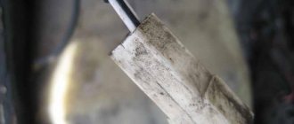
1 . 8 The communication coil came off from the VZ pad on the inside
Abbreviations: IS – status indicator; VZ – ignition switch; OK – training key; RK – working key; RC – remote control; KSUD – engine control system controller; ECU - electronic control unit
The Kalina electrical package control unit is used to automatically raise and lower windows and control doors. Additionally, it makes it possible to control alarm activation and trunk opening.
If we are talking about the luxury configuration of Kalina 2, then the electrical package control unit is responsible for blocking the ignition switch. That is why any malfunctions in its operation negatively affect the driving performance of the vehicle.
Lada Kalina dashboard diagram
1,2,3,4 – blocks of the instrument panel wiring harness to the blocks of the rear wiring harness;
5,6 – blocks of the instrument panel wiring harness to the blocks of the front wiring harness; 7 – block of the instrument panel wiring harness to the block of the wiring harness 8 – block of the instrument panel wiring harness to the block of the front wiring harness; 9 – lighting control module; 10 – ignition switch; 11 – on-board computer mode switch; 12 – windshield wiper switch; 13 – sound signal switch; 14 – light signaling switch; 15 – instrument cluster; 16 – evaporator temperature sensor; 17 – interior air temperature sensor; 18 – air conditioner switch; 19 – controller of the automatic climate control system; 20 – heater damper gearmotor; 21 – rear window heating switch; 22 – alarm switch; 23 – brake signal switch; 24 – cigarette lighter; 25 – electric amplifier control unit; 26,27 – blocks of the instrument panel wiring harness to the radio; 28 – backlight lamp for the heater control panel; 29 – illuminator; 30 – mounting block: 31 – heater electric motor switch; 32 – heater electric motor; 33 – additional resistance of the heater electric motor; 34 – glove box lighting; 35 – glove box lighting switch; 36 – control unit of the APS-6 automobile anti-theft system; 37 – driver airbag module; 38 – passenger airbag module; 39,40 – blocks of the instrument panel wiring harness to the blocks of the ignition system wiring harness. KZ – additional starter relay; K4 – additional relay; K5 – relay-interrupter for direction indicators and hazard warning lights; K6 – windshield wiper relay; K7 – headlight high beam relay; K8 – sound signal relay; K9 – relay for turning on fog lights; K10 – relay for turning on the heated rear window; K11 – electric seat heating relay; K12 – air conditioner compressor clutch activation relay;
Personalize existing features
The manufacturer has provided for the timing of regular technical inspections, which are mandatory. For non-compliance, the company reserves the opportunity to deprive the car owner of the right to free service.
The most vulnerable is the comfort block, which includes many logical circuits. Its purpose boils down to the following functions:
- activation of interior lighting;
- adjusting the operation of car alarms;
- turning on the heated rear window;
- automatic mirror adjustment;
- control of electric windows;
- remote control of locks.
The manufacturer has provided the ability to personalize each element. To do this, the electrical package control unit must be recoded at an authorized automotive center. Using official software, the wizard will add or remove certain features. If everything is done correctly, 20 minutes after requesting the appropriate service, you can safely use the “iron horse”.
According to reviews from car enthusiasts, the Lada Kalina car is distinguished by electronic filling with increased sensitivity to operating conditions. Aggressive driving style and minor damage lead to malfunctions.
As a result, you need to visit a service station to replace the device. To do this, remove the control unit, which must be done as follows:
- turn off the battery;
- unscrew the screws from the driver's seat;
- Use a ratchet wrench to remove the nut;
- the plastic plug is squeezed out completely;
- carefully pull out the seat;
- remove the seat by dismantling the terminals;
- remove the cover plate.
The replacement procedure on the Kalina 2 model is completed by folding the carpet and installing a new block. After this, all procedures are carried out in reverse order.
Ignition system diagram Lada Kalina Lux
1 – oil pressure warning lamp sensor; 2 – coolant temperature indicator sensor; 3 – additional fuse block; 4 – fuses for the electric fan of the engine cooling system; 5 – electric fuel pump relay; 6 – relay for the electric fan of the engine cooling system; 7 – ignition relay; 8 – relay 2 of the electric fan of the engine cooling system; 9 – relay 3 of the electric fan of the engine cooling system; 10 – electric fan of the engine cooling system; 11 – throttle position sensor; 12 – idle speed regulator; 13 – coolant temperature sensor; 14 – diagnostic block; 15 – ignition system harness block to the instrument panel harness block; 16 – solenoid valve for purge of the adsorber; 17 – speed sensor; 18 – ignition system harness block to instrument panel harness block 2; 19 – mass air flow sensor; 20 – crankshaft position sensor; 21 – oxygen sensor; 22 – controller; 23 – rough road sensor; 24 – diagnostic oxygen sensor; 25 – ignition coil harness block to the ignition system harness block; 26 – ignition coils: 27 – ignition system harness block to the ignition coil harness block; 28 – spark plugs; 29 – nozzles; 30 – resistor; 31 – air conditioning system pressure sensor; 32 – blocks of the ignition system harness and injector wiring harness; 33 – phase sensor; 34 – knock sensor.
Ignition system wiring harness -11184-3724026-10. Ignition coil wiring harness -1118-3724148-00. Injector wiring harness -11184-3724036. A – to the “plus” terminal of the battery.
Tell me, where can I get the pinout for the connector of the control unit for the “Lux” electrical package? I wanted to install a pager and a sensor, I found everything, took it apart - and there were 2 connectors, 20 thin and a second connector, 10 thick. The third connector is not connected. THERE WAS a rumor that the block on the luxury ones was a Priorovsky one, but I also couldn’t find a description of it, and besides, it is combined there with the APS-6. There is no need to send it to the search, because... Finding anything on a new engine is almost unbelievably lucky
Well, no one installed an alarm on the luxury version? I downloaded the Priora diagram - the Priora unit has 20 contacts and 2 more connectors, everything seems to fit together, but the Priora for the additional sensor has a 3-pin connector, and mine has this connector with about 8-10 contacts. And there is still no description.