The engine fuel system is a “blood” network. The main element of this system is the fuel pump, which, like a heart, pumps gasoline from the gas tank to the engine. If for some reason this pump stops working, then it is no longer possible to start the engine. Let's look at the main reasons why the fuel pump on the Lada Kalina/Granta/Priora does not work.
Checking the fuel pump Lada Kalina/Granta
If after turning the ignition key there is no buzzing sound from the fuel pump, then the first thing to check is the fuse and the fuel pump relay. In the Lada Kalina and Lada Granta mounting block, the fuel pump fuse is F21 (15A), and the fuel pump relay is K12. If the fuse is good, do the following:
- Turn on the ignition
- Remove the fuel pump relay
- Apply +12V to pin No. 11 of the diagnostic block, or place a jumper between 87 and 30 relay pins
- Check by ear that the fuel pump is turned on
If the fuel pump does not turn off, then check:
- Wiring and contacts between the fuel pump and the diagnostic block/fuel pump relay. To do this, check the voltage at the fuel pump chip using a test lamp or multimeter.
- There is no connection between the fuel pump and the vehicle ground. Apply the mixture to the fuel pump (located under the rear seat).
- The fuel pump is faulty. To check it, apply +12V directly to the contacts of the fuel pump (Attention! Remaining gasoline may ignite from a spark!).
In rare cases, the fuel pump does not work due to:
- ECU (controller) malfunction
- alarm malfunctions
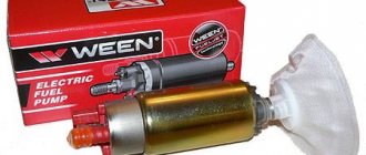
Tips for motorists
The electric fuel pump, located in the gas tank of a Lada Kalina passenger car, can be considered the heart of the fuel injection engine power system. It is he who creates the necessary pressure in the ramp, the magnitude of which determines the operation of the electromagnetic injectors. The controller controls turning the fuel pump on and off. When the driver turns the key to the “ignition on” position, voltage is supplied to the fuel pump terminals for 3-5 seconds through the main relay. And as soon as the engine crankshaft begins to rotate, then, based on the signal from the DPKV sensor, the controller turns on the fuel pump relay and the voltage to its terminals goes through the contacts of this relay.
Checking the fuel pump Lada Priora
On the Lada Priora, the fuel pump relay and its fuse are located in an additional mounting block near the left foot of the front passenger. The fuse is marked F3 (15A), and the relay is K2.
First of all, we check the fuel pump fuse, and if necessary, replace it with a similar new one. We check the wiring and the fuel pump itself in the same way as on Lada Kalina and Lada Granta cars (see above).
As a reminder, don't forget to change your fuel filter regularly.
Schematic electrical diagrams, connecting devices and pinouts of connectors
The fuel pump on a car is designed to supply fuel to the combustion chamber. Its operation is controlled using a relay. On a VAZ (depending on the model), the fuel supply unit can be electrical or mechanical - it all depends on the fuel supply system. On a fuel-injected car, the fuel pump is located in the tank. When the ignition is turned on, voltage is supplied to the terminals of the unit and it begins to pump fuel. If the required pressure is created in the system, the relay automatically turns off the fuel pump - the engine is ready to start.
When the ignition is turned on, the relay creates pressure in the fuel lines by turning on the fuel pump (BN) for a couple of seconds. After this, the BN will work either when the engine is cranked by the starter, or when the engine is running.
Sometimes this system needs repairs - there is nothing complicated here, and the editors of the 2Skhema.ru website will tell you how to do it yourself. Let's start with the BN pinout, then we will indicate it on the diagrams and at the end there will be instructions for replacing the fuel supply elements.
Replacing the fuel pump Kalina
Before replacement, read the operating manual to learn the location of the fuel system element, the specifics of the adjacent fuel lines and the types of fasteners. When working, it is important to follow the outlined algorithm so as not to disrupt the functioning of the fuel supply system. Damage to the fuel line or improper assembly of the fuel module can lead to engine damage and even a car fire.
To carry out the work, the car owner will need:
- pliers;
- hammer;
- screwdrivers for flat and Phillips slots.
Sequence of replacing the fuel pump Lada Kalina
Before starting work, you need to “de-energize” the Kalina by disconnecting the battery terminals. Repair procedures should be carried out away from fire and places where sparks could be generated.
- We dismantle the rear seat and floor trim;
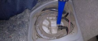
- Under the seat there is a fuel tank cap secured with 4 “cross” bolts. Unscrew;
- Now the car owner has access to the top cover of the fuel pump;
- Now you need to “unhook” all the plugs and fittings from the pump. To remove the power plug, press the latch upward and pull the plug to the side. The power plug itself is located on the left side of the fuel pump cover;
- To remove the fittings, you must use pliers. The locking clamp is pressed out by hand, after which the fitting itself is removed using pliers. The main thing is not to confuse the fittings: the lock on the top is green, the lock on the bottom is metal;
- After dismantling the fittings, clean the fuel pump cover as much as possible - dirt will not get into the gas tank;
- Removing the fuel pump cover retaining ring: take a flat-head screwdriver, place it against the outline of the ring and lightly tap it with a hammer so that the ring moves clockwise. The latch should pop out and the cover will be accessible;
- Open the cover and carefully pull the pump up so as not to damage the adjacent elements. Additionally, make sure that no sand gets into the tank;
- We take the new pump and carefully immerse it in the technological hole. We attach the lid. Next, assembly is carried out in reverse order.
After the repair, you need to start the Kalina and drive for a few minutes. During operation, it is necessary to check the operation of the internal combustion engine in different speed ranges, at idle speed; You also need to be attentive to various noises in the fuel tank.
The Kalina fuel pump relay is an important element for ensuring stable operation of the car. The internal combustion engine is the main unit for the movement of road transport. With the advent of electric vehicles, the share of cars with internal combustion engines is decreasing, but the vast majority will be provided with cars powered by hydrocarbon raw materials for the coming decades.
For stable operation of the flaming engine of any car, including the Lada Kalina, a stable supply of a sufficient amount of fuel is necessary.
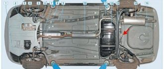
The main element of the fuel system on Kalina is the fuel pump. The fuel tank on the Lada Kalina is located in the rear of the body, therefore, the delivery of gasoline through the supply pipes to the injector sprinklers must be constant and forced.
Other elements of the car's fuel system, in addition to the tank and fuel pump, are a fine filter and fuel supply pipes.
Pinout of fuel pump VAZ 2107
1 – radiator fan drive motor; 2 – mounting block block; 3 — idle speed sensor; 4 – engine ECU; 5 – potentiometer; 6 – set of spark plugs; 7 – ignition control unit; 8 – electronic crankshaft position sensor; 9 – electric fuel pump; 10 – indicator of the number of revolutions; 11 – lamp for monitoring the health of electronic systems and the brake system; 12 – ignition system control relay; 13 – speedometer sensor; 14 – special factory connector for reading errors using the BC; 15 – injector harness; 16 – adsorber solenoid valve; 17, 18, 19,20 – fuse box for repairing the mounting block that protects the injection system circuits; 21 – electronic fuel pump control relay; 22 – electronic relay for controlling the exhaust manifold heating system; 23 – exhaust manifold heating system; 24 – fuse protecting the heater circuit; 25 – electronic air sensor; 26 – coolant temperature control sensor; 27 – electronic air damper sensor; 28 – air temperature sensor; 29 – pressure control sensor and low oil pressure lamp.
You can check the fuel pump on a VAZ 2107 simply by checking the voltage at its connection block with a tester. The presence of voltage will indicate a malfunction of the electric motor. Instead of a tester (multimeter), you can use a test lamp to diagnose a malfunction.
In the absence of one, this can be done by disconnecting the connection block for the fuel pump and fuel level control and applying voltage with wires from the battery to the place where the gray wire is connected +12 and to the place where the black wire is connected - minus. A humming pump will indicate a faulty fuse, power circuit or ECU.
Causes of gasoline pump malfunction
If Kalina’s fuel pump does not pump, then the reasons will be in the equipment itself or in other parts of the system. First, you should make sure that there is fuel in the tank, a spark in the spark plugs, the battery is charged, and the starter is working. If everything is in order, then you need to continue checking. If the cause of the malfunction is identified, for questions regarding the purchase of auto parts to eliminate it, you can contact the specialized online store automechanika38.rf.
Electromechanical equipment may not function correctly or stop working due to a malfunction in either the mechanical or electrical components of the system.
- The fuel pump fuse has blown - you should remove the element from the fuse box (located in the engine compartment). If the contact has visible damage, the part needs to be replaced.
- The equipment relay is faulty - check the electrical wiring, contacts between the unit and the diagnostic block, as well as the relay. Using a test lamp or multimeter, check the presence of voltage at the pump chip. A correctly operating relay makes clicks when the ignition is turned on, after the required pressure has been reached in the fuel line.
- There is no contact of the equipment with “ground” - it is necessary to apply ground to the part chip. The wire is located under the instrument panel and runs through the interior of the car. It is worth checking it, cleaning the contacts, and fixing them securely on the pump.
- The electronic control unit is faulty - the ECU needs to be repaired or replaced.
- A breakdown in the car alarm, poor installation of the security system - electrical wires may be mixed up, errors may have been made when connecting the alarm.
- Insufficient pressure in the fuel line may be the result of contamination of the gasoline filter or the filter mesh of the pump itself.
Many car owners prefer to drive with a half-empty fuel tank. However, the fuel pump in this case often overheats, which will ultimately lead to equipment malfunction. The reasons why the fuel pump on Kalina does not turn on may be the breakdown of individual parts of the unit. To determine the problem, it is necessary to remove the equipment and diagnose it.
Pinout BN VAZ 2108, 2109, 21099
The fuel pump activation relay (2) is shown by an arrow.
1 — nozzles; 2 — spark plugs; 3 — ignition module; 4 — diagnostic block; 5 - controller; 6 — block connected to the instrument panel harness; 7 - main relay; 8 - main relay fuse; 9 — electric fan relay; 10 — controller power supply fuse; 11- electric fuel pump relay; 12 — fuel pump power circuit fuse; 13 — mass air flow sensor; 14 — throttle position sensor; 15 — coolant temperature sensor; 16 — idle speed regulator; 17 — knock sensor; 18 — crankshaft position sensor; 19- oxygen sensor; 20- APS control unit; 21 — APS status indicator; 22 — speed sensor; 23 — electric fuel pump with fuel level sensor; 24 — solenoid valve for purge of the adsorber; 25 — block connected to the ignition system harness; 26 — instrument cluster; 27 — ignition relay; 28 — ignition switch; 29 — mounting block; 30 — electric fan of the cooling system;
Diagnosis and Troubleshooting
It is relatively simple to verify that the electrical network is faulty - this can be done without removing the fuel pump. When the sound of its operation is not heard when the ignition is turned on, you must immediately check the fuse responsible for this circuit. It is installed in a block mounted at the bottom in front of the front passenger seat. You need to remove the block cover, find the fuse marked F3, rated for 15 A, and replace it. This kind of work can be done on the road.
If the operation of the fuel pump has not resumed, you should switch your attention to relay K2, located in the same block. It closes the power circuit of the pumping device according to the controller signal
You can also check the serviceability of the relay in road conditions, for which you will need a piece of copper wire. Diagnostics are carried out in the following order:
- Remove relay K2 from the connector.
- Turn on the ignition.
- Using a wire, connect the contacts marked “30” and “87”; the numbers are marked on the relay. Another option is to apply power to pin “11” located in the diagnostic connector. The +12 V voltage can be taken nearby, from the cigarette lighter.
- If you hear the pump humming, then you need to change relay K2.
If after the above manipulations the unit is still “silent”, it is necessary to check the integrity of the wiring and the reliability of the contact at the place of its connection. This will require a device, so it will not be possible to carry out such work in the middle of a field. Unless you can check the serviceability of the fuel pump itself by disconnecting the connectors from it and supplying 12 V directly from any convenient source. If the pump still does not hum, it should be replaced.
It will not be possible to diagnose insufficient fuel supply to the injectors under road conditions, unless you carry a pressure gauge with a corresponding hose for connection to the fuel rail. The amount of gasoline supplied is characterized by the pressure in the network, to measure which you will need a pressure gauge. The check is performed as follows:
- Twist off the plastic cap covering the diagnostic fitting. It is located at the end of the fuel rail and is a regular spool.
- Press the spool rod to release the pressure in the line. In case of gasoline leakage, place a small container under the spool. Perhaps the malfunction will make itself felt already at this stage if there is no pressure in the network and no fuel flows from the fitting.
- Unscrew the spool and put the hose from the pressure gauge onto the fitting. With the ignition off, apply 12 V directly to the pump. To clearly record the readings, it must work for at least 10 seconds.
VAZ 2110 fuel pump pinout
If the fuel pump works directly when connected to the battery, then you will have to ring the wires going from it to the fuel pump relay, and if it does not work, then either replace it with a new one, or you will have to disassemble it and look for a fault inside the fuel pump.
Self-removal of equipment
When the fuel pump on the Lada Kalina does not turn on, you can dismantle it yourself. The unit is located in the rear half of the machine. To remove it, you need to have a Phillips screwdriver and pliers on hand.
- The negative cable is removed from the battery.
- The pressure in the fuel system is relieved.
- The rear seat of the car is removed.
- Under the carpet on the floor there is an access cover to the equipment.
- The four bolts holding the cover are unscrewed.
- The wires are disconnected from the part connector.
- The petrol hoses are disconnected by pressing the screwdriver on the block.
- The plate securing the fuel pump housing is unscrewed (clockwise).
- The equipment is removed from the gas tank.
After removal, the part can be diagnosed.
Pinout BN VAZ 2113, 2114, 2115
— block headlights; — gearmotors for headlight cleaners*; - fog lights*; — ambient temperature sensor; - sound signals; — engine compartment lamp switch; — electric motor of the engine cooling system fan; — generator; — low oil level indicator sensor; — washer fluid level sensor; — front brake pad wear sensor; — wire tips connected to the common windshield washer pump**; — windshield washer pump; — headlight washer pump*; — wire ends for connecting to the rear window washer pump on VAZ-2113 and VAZ-2114 cars; — low oil pressure indicator sensor; — engine compartment lighting lamp; — wire lug for connecting to the wiring harness of the engine control system; — gear motor for windshield wiper; — starter; — a block connected to the wiring harness of the ignition system on carburetor cars; — coolant temperature indicator sensor; — reversing light switch; — low brake fluid level indicator sensor; - accumulator battery; — low coolant level indicator sensor; — relay for turning on fog lights; - mounting block; — brake light switch; — plug socket for a portable lamp; — hydrocorrector scale illumination lamp; — switch for the parking brake indicator lamp; — block for connecting a backlight lamp; — switch for instrument lighting lamps; - Understeering's shifter; - hazard warning switch; — front seat heating element relay; — ignition switch; — rear fog light circuit fuse; - fuse for the front seat heating elements; — door lock circuit fuse; — front ashtray illumination lamp; — ignition relay; - cigarette lighter; — glove box lighting lamp; — switch for the glove compartment lighting lamp; — heater fan electric motor; — additional resistor for the heater electric motor; — heater fan switch; - heater switch illumination lamp; — lamp for illuminating the heater levers; — gear motors for electric windows of the front doors; — power window switch for the right front door (located in the right door); — gear motors for locking front door locks; — wires for connecting to the right front speaker; — gearmotors for locking rear doors; — wires for connecting to the right rear speaker; — door lock control unit; — wires for connection to radio equipment; — headlight cleaner switch*; — rear window heating element switch; — relay for turning on the rear fog lights; — block for connection to the heating element of the right front seat; — rear fog light switch; — switch for the heating element of the right front seat; — fog light switch*; — switch for external lighting lamps; — left front seat heating element switch; — block for connection to the heating element of the left front seat; — wires for connecting to the left front speaker; — power window switch for the left front door (located in the left door); — power window switch for the right front door (located in the left door); — wires for connecting to the left rear speaker; — side direction indicators; — courtesy light switches on the front door pillars; — courtesy light switches on the rear door pillars; - lampshade; — ceiling lamp for individual interior lighting; — block for connecting to the wiring harness of the electric fuel pump; — trunk light switch; — instrument cluster; — trunk lighting lamp; — display unit of the on-board control system; - trip computer*; — block for connecting the wiring harness of the engine control system; — rear exterior lights; — rear interior lights; — pads for connecting to the rear window heating element; — license plate lights; — additional brake signal located on the spoiler.
Causes of gasoline pump malfunction
If Kalina’s fuel pump does not pump, then the reasons will be in the equipment itself or in other parts of the system. First, you should make sure that there is fuel in the tank, a spark in the spark plugs, the battery is charged, and the starter is working. If everything is in order, then you need to continue checking. If the cause of the malfunction is identified, for questions regarding the purchase of auto parts to eliminate it, you can contact the specialized online store automechanika38.rf.
Electromechanical equipment may not function correctly or stop working due to a malfunction in either the mechanical or electrical components of the system.
- The fuel pump fuse has blown - you should remove the element from the fuse box (located in the engine compartment). If the contact has visible damage, the part needs to be replaced.
- The equipment relay is faulty - check the electrical wiring, contacts between the unit and the diagnostic block, as well as the relay. Using a test lamp or multimeter, check the presence of voltage at the pump chip. A correctly operating relay makes clicks when the ignition is turned on, after the required pressure has been reached in the fuel line.
- There is no contact of the equipment with “ground” - it is necessary to apply ground to the part chip. The wire is located under the instrument panel and runs through the interior of the car. It is worth checking it, cleaning the contacts, and fixing them securely on the pump.
- The electronic control unit is faulty - the ECU needs to be repaired or replaced.
- A breakdown in the car alarm, poor installation of the security system - electrical wires may be mixed up, errors may have been made when connecting the alarm.
- Insufficient pressure in the fuel line may be the result of contamination of the gasoline filter or the filter mesh of the pump itself.
Many car owners prefer to drive with a half-empty fuel tank. However, the fuel pump in this case often overheats, which will ultimately lead to equipment malfunction. The reasons why the fuel pump on Kalina does not turn on may be the breakdown of individual parts of the unit. To determine the problem, it is necessary to remove the equipment and diagnose it.
Replacing an electric fuel pump on a VAZ
- Reduce pressure in the fuel supply system.
- Using the fuel supply hose tip clamp, disconnect 2 hoses in turn.
- Unscrew the 8 nuts around the circumference of the clamping ring and remove it.
- A wire with negative polarity is attached to one of the nuts; it must be removed carefully.
- We take the electric pump block out of the fuel tank, tilting it slightly, to keep the fuel level indicator sensor lever intact, otherwise it will produce incorrect parameters.
- Remove the sealing rubber ring of the fuel block. If its properties are lost, the product must be replaced.
- Install the pump in reverse order.
When installing fuel hoses, focus on the direction of fuel supply indicated by the arrows, and the installation arrow on the electric pump cover should point towards the rear of the car!
Fuel pump device
Modern cars use two types of fuel pumps - mechanical or electric. The former are used in carburetor engines, the latter in injection engines.
The mechanical pump is usually installed on the body of the gas tank, while the electric pump is installed inside the tank. Some automakers use both types of pumps at once.
Mechanical pump
The mechanical fuel pump is quite large. Its main elements are:
The fuel supply system of the VAZ 1118 Lada Kalina car has 2 stages of fuel filtration - coarse and fine cleaning. The first is a fine mesh made of plastic, the second is an “accordion” made of porous paper. Both cleaning elements gradually become clogged during operation and after a certain period of time require replacement. Many car enthusiasts perform this operation on their own, because it is quite simple. You too can take on this work once you have read the instructions for its implementation.
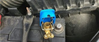
Where is the fuel pump relay located?
Where is the fuel pump relay located? The installation location of the relay varies depending on the make of the car. Most often, it is located under the hood, in the fuse and relay box.
The fuel pump relay is designed in the circuit to prevent accidental application of high voltage to the fuel pump winding. The relay is standard and consists of a plastic body and coils with contacts. It is located in the car interior near the console. To access it, you need to remove the protection cover.
In appearance, it is a small box that resembles a “plug” with an American type of output. Each terminal has a marking that indicates the following: 31 – mass; 30– +12V constant (regardless of ignition); 15– +12 with the ignition on; 50– +12 when the starter is running; TD – signal from the ignition system; TF – engine temperature signal from the injection control unit KE. Outputs: 87 – supplies power to the fuel pump; 87H – oxygen sensor heating; 87V – turns on the starting injector.
But sometimes the fuel pump does not turn on when the key is turned in the ignition. With what it can be connected? First of all, the fuse, although if it had blown, it would not work at all. Maybe the contact is bad?
If the electric fuel pump does not show any signs of life when the ignition is turned on, this does not mean that it has burned out. The cause of the malfunction may also be a relay. The easiest way to test your hearing is that when you turn on the ignition, the relay should click. If you don’t hear a click, there is a high probability that the “relay” is faulty.
It’s easy to check the functionality of the pump itself, so we do this:
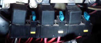
- remove the protective casing, under which there is a block with relays and fuses;
- we unscrew the fastenings of the block, remove it, it remains attached to the wires;
- we pull the RB out of the block, place a jumper between two opposite contacts, thus directly supplying power to the BN;
- if with such a connection the electric motor of the pump begins to make noise, it means that the BN itself is working, most likely the fault is hidden in the relay;
- if there is no voltage on any of the contacts on the RB block, you should look for a break in the wiring; there may also be poor contact at the place where the wire is attached to the terminal.
Why is there no power to the fuel pump?
A gasoline pump is necessary to supply fuel from the gas tank to the fuel rail, creating the necessary pressure.
Electrical circuit for controlling a fuel pump.
The fuel pump is an electromechanical device, so its breakdown can be due to both insufficient power supply and mechanical damage. It is not difficult to detect a lack of tension.
- To do this, turn on the ignition and listen.
- When you turn the key, the fuel pump starts, which creates a slight hum . If you don’t hear a buzz, then most likely the device is de-energized . You have already found out that there is no voltage supplied to it.
Causes of malfunction
- Wiring problems . Checked with a regular 12-volt light bulb. We connect it to an external connector. When you turn the ignition key, the light should light up. If not, the wiring is faulty. You checked this point with a multimeter. Raise the rear sofa. Find this place. Unscrew it, there is a fuel pump inside. Cover securing screws. The fuel pump itself.
- Terminal oxidation . Over time, the terminals tend to oxidize, making it difficult to supply power to the pump. If this happens, you need to clean the contacts. In case of severe oxidation, it is advisable to re-solder the terminals. The terminal on the fuel pump itself may also burn out. The contact may also become charred on the fuel pump cover block.
- Problems with ground contact . This malfunction can be detected by the fuel level sensor, which begins to work incorrectly.
- Fuel pump relay malfunction .
It is not difficult to identify a breakdown. When the ignition is turned on, the click of the relay is clearly audible, after which it turns off with the same click. If these sounds are not heard, then the relay contacts should be cleaned or replaced. The fuel pump relay is not located on the main unit, but on an additional one, located behind the lining of the central tunnel, almost under the stove. - Replacing the fuse . Located next to the gearbox in the passenger compartment in a special fuse box. 15 A element marked Fuel Pump . We remove it from the socket and inspect the contact. If it is damaged, replace the fuse. To be sure, it is better to call it. The block with a separate fuse for the fuel pump is located here. Protective cover for the fuse box. The arrow marks the fuse we need.
- Additional alarm malfunction .
In most cases, the alarm is connected to a break in the power supply to the fuel pump, or the spark plugs are broken. More competent installers install a relay that misleads the thief by turning on the fuel pump, but turning it off after five seconds. Additional alarm.
General diagram of electrical equipment of VAZ 1118
1 — block headlight; 2 — windshield wiper gear motor; 3 - generator; 4 - battery; 5 - starter; 6 — sound signal; 7 — hood open sensor; 8 — power window switch for the right front door; 9 — motor-reducer for window lifter of the right front door; 10 — electric pump for windshield washer; 11 — connecting blocks of wires for connecting the right (front) speaker of the audio system; 12 — electric drive for locking the lock of the right front door with an open door sensor; 13 — ambient air temperature sensor; 14 — connecting block of the wiring harness for connection to the engine control system harness; 15 — electric drive for locking the left front door lock (with an open door sensor and a central locking switch); 16 — sensor of insufficient brake fluid level; 17 — connecting blocks of wires for connecting the left (front) speaker of the audio system; 18 — right front door power window switch (installed on the driver’s door); 19 — left front door power window switch; 20 — central locking switch; 21 — motor-reducer for window lifter of the right front door; 22 — remote control unit; 23 — immobilizer control unit (APS-6); 24 — mounting block; 25 — instrument panel; 26 — right side turn signal; 27 — glove box lighting lamp; 28 — switch for the glove compartment lighting lamp; 29 — brake signal switch; 30 — ignition switch (lock); 31 — lighting control unit; 32 — steering column switches; 33 — left side direction indicator; 34 — connecting blocks of wires for connecting the left (rear) speaker of the audio system; 35 — electric drive for locking the left (rear) door with an open door sensor; 36 — electric heater fan; 37 — additional heater resistor; 38 — heater switch; 39 — alarm switch; 40 — reverse lock solenoid switch; 41 — rear window heating switch; 42 — connecting blocks of wires for connecting the right (rear) speaker of the audio system; 43 — electric drive for locking the right rear door lock (with a door open sensor); 44 — fuel module of the engine control system; 45 — reverse light switch; 46 — parking brake warning lamp switch; 47 — cigarette lighter; 48 — reverse lock solenoid; 49 — connecting blocks of wires for connecting the head unit of the audio system; 50 — backlight lamps on the trim of the center console of the instrument panel; 51 — electric power steering control unit; 52 — interior lamp; 53 — rear light; 54 — block for connecting the electric drive for locking the trunk lid lock*; 55 — luggage compartment lid open sensor; 56 — license plate lights; 57 — additional brake light; 58 — rear window heating element; 59 — luggage compartment lighting lamp.
The module has been removed, what next?
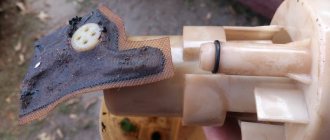
Having disengaged the four latches, the module cover is disconnected from the “glass”. Then, the “glass” can be cleaned, the pump screen can be replaced, and so on. Details are illustrated in the photo:
The mesh will be fixed in front of the intake hole
The module is assembled in the reverse order. And when installing it in place, you need to make sure that the plastic protrusion coincides with the slot on the tank:
Here are a couple more tips:
- Do not turn on the pump motor “in the air” (the windings overheat);
- The module is replaced together with the sealing ring, which must be included in the kit.
In a Lada Kalina car, as in any other, you can observe the following effect: symptoms indicate that the fuel pump is not working, but its engine is humming. Then you need to clean or replace the mesh (discussed above).
Be careful when disconnecting or connecting fuel hoses. The fittings on the module cover are very fragile. They are easy to damage.
There are various folk tips for repair and tuning. One sounds like this: the pump is cleaned without dismantling it, but simply by turning on the electric motor in reverse polarity. It is this advice that is not recommended to be followed.
Lada Kalina dashboard diagram
1,2,3,4 – blocks of the instrument panel wiring harness to the blocks of the rear wiring harness; 5,6 – blocks of the instrument panel wiring harness to the blocks of the front wiring harness; 7 – block of the instrument panel wiring harness to the block of the wiring harness 8 – block of the instrument panel wiring harness to the block of the front wiring harness; 9 – lighting control module; 10 – ignition switch; 11 – on-board computer mode switch; 12 – windshield wiper switch; 13 – sound signal switch; 14 – light signaling switch; 15 – instrument cluster; 16 – evaporator temperature sensor; 17 – interior air temperature sensor; 18 – air conditioner switch; 19 – controller of the automatic climate control system; 20 – heater damper gearmotor; 21 – rear window heating switch; 22 – alarm switch; 23 – brake signal switch; 24 – cigarette lighter; 25 – electric amplifier control unit; 26,27 – blocks of the instrument panel wiring harness to the radio; 28 – backlight lamp for the heater control panel; 29 – illuminator; 30 – mounting block: 31 – heater electric motor switch; 32 – heater electric motor; 33 – additional resistance of the heater electric motor; 34 – glove box lighting; 35 – glove box lighting switch; 36 – control unit of the APS-6 automobile anti-theft system; 37 – driver airbag module; 38 – passenger airbag module; 39,40 – blocks of the instrument panel wiring harness to the blocks of the ignition system wiring harness.
KZ – additional starter relay; K4 – additional relay; K5 – relay-interrupter for direction indicators and hazard warning lights; K6 – windshield wiper relay; K7 – headlight high beam relay; K8 – sound signal relay; K9 – relay for turning on fog lights; K10 – relay for turning on the heated rear window; K11 – electric seat heating relay; K12 – air conditioner compressor clutch activation relay;
Instrument panel wiring harness – 11186-3724030-20.
Ignition system diagram Lada Kalina Lux
1 – oil pressure warning lamp sensor; 2 – coolant temperature indicator sensor; 3 – additional fuse block; 4 – fuses for the electric fan of the engine cooling system; 5 – electric fuel pump relay; 6 – relay for the electric fan of the engine cooling system; 7 – ignition relay; 8 – relay 2 of the electric fan of the engine cooling system; 9 – relay 3 of the electric fan of the engine cooling system; 10 – electric fan of the engine cooling system; 11 – throttle position sensor; 12 – idle speed regulator; 13 – coolant temperature sensor; 14 – diagnostic block; 15 – ignition system harness block to the instrument panel harness block; 16 – solenoid valve for purge of the adsorber; 17 – speed sensor; 18 – ignition system harness block to instrument panel harness block 2; 19 – mass air flow sensor; 20 – crankshaft position sensor; 21 – oxygen sensor; 22 – controller; 23 – rough road sensor; 24 – diagnostic oxygen sensor; 25 – ignition coil harness block to the ignition system harness block; 26 – ignition coils: 27 – ignition system harness block to the ignition coil harness block; 28 – spark plugs; 29 – nozzles; 30 – resistor; 31 – air conditioning system pressure sensor; 32 – blocks of the ignition system harness and injector wiring harness; 33 – phase sensor; 34 – knock sensor.
Ignition system wiring harness -11184-3724026-10. Ignition coil wiring harness -1118-3724148-00. Injector wiring harness -11184-3724036. A – to the “plus” terminal of the battery.