Let's continue. I started connecting. Let's go in order. First I’ll tell you what and how, and then how I did it.
Let's start with the general outline.
Now let's see what needs to be changed in the engine compartment.
Let's start with the fan. This braid has a single contact; if you open the insulation a little, you can see that it has a white-black wire.
The fan worked differently on different units, but the main feature was that it was turned on by a sensor on the radiator. Now it will be turned on by the injector unit. And instead of the old scheme
I will not consider all the sensor plugs, but will consider only those points that baffle a novice electrician)))) There are two brown wires in the engine compartment
These are the “minuses” that are named G1 and G2 in the SUD diagram. They need to be screwed onto the body. Usually they are screwed onto the cylinder head in the area of the thermostat.
Also one black wire
In fact, this is an optical illusion. This is actually the red wire. You can verify this by moving the insulation back a little. This is “+12” which is attached directly to the battery. It feeds the "brains".
Well, that seems to be all. There was nothing else unknown in the engine compartment. Now let's see what's going on inside the car.
Let's look at the connections of the fuel pump.
In the carb version, two wires approached the tank
The fact is that in a carburetor circuit, the external fuel pump is located in the engine compartment, and these wires simply go to the gasoline level sensor. One, blue and red, supplies voltage, the second, pink, transmits information about the availability of gasoline. In this case (injector), we have a fuel pump in the tank. and it is connected using a block. In order not to pull unnecessary wires, you should do this - connect the old wires to the block as follows: the pink wire of the block to the pink wire, the gray wire of the block to the green-red, black and white - ground, blue is not needed.
Now we have power supply connected to the fuel pump and a contact indicating the fuel level. We throw the black and white wire to minus. those. frame. The blue-red wire is not needed. Everything in the gas tank area is connected.
Pinout of fuel pump VAZ 2107
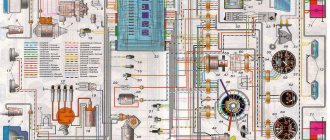
1 – radiator fan drive motor; 2 – mounting block block; 3 — idle speed sensor; 4 – engine ECU; 5 – potentiometer; 6 – set of spark plugs; 7 – ignition control unit; 8 – electronic crankshaft position sensor; 9 – electric fuel pump; 10 – indicator of the number of revolutions; 11 – lamp for monitoring the health of electronic systems and the brake system; 12 – ignition system control relay; 13 – speedometer sensor; 14 – special factory connector for reading errors using the BC; 15 – injector harness; 16 – adsorber solenoid valve; 17, 18, 19,20 – fuse box for repairing the mounting block that protects the injection system circuits; 21 – electronic fuel pump control relay; 22 – electronic relay for controlling the exhaust manifold heating system; 23 – exhaust manifold heating system; 24 – fuse protecting the heater circuit; 25 – electronic air sensor; 26 – coolant temperature control sensor; 27 – electronic air damper sensor; 28 – air temperature sensor; 29 – pressure control sensor and low oil pressure lamp.
You can check the fuel pump on a VAZ 2107 simply by checking the voltage at its connection block with a tester. The presence of voltage will indicate a malfunction of the electric motor. Instead of a tester (multimeter), you can use a test lamp to diagnose a malfunction.
In the absence of one, this can be done by disconnecting the connection block for the fuel pump and fuel level control and applying voltage with wires from the battery to the place where the gray wire is connected +12 and to the place where the black wire is connected - minus. A humming pump will indicate a faulty fuse, power circuit or ECU.
Purpose
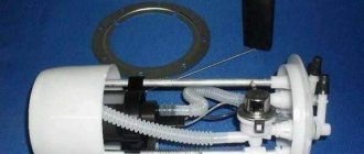
Electric fuel pump VAZ 2110
The principle operation of an electric fuel pump is based on pushing fuel under pressure into the engine. Conventional VAZ fuel pumps suck gasoline from the gas tank; a small gap from the pump to the carburetor allows it to operate at low pressure. Electric fuel pumps of the first VAZ cars worked at the same speed. The industry has launched the production of pumps that meet the growing requirements of the automotive industry; now their operation is completely dependent on the speed of the engine.
Note. The vehicle's electronic system controls the operation of the fuel pump. It corresponds to several factors: ambient temperature, what position the throttle is in, and the composition of the exhaust gases.
Electric fuel pumps operate under pressure, resulting in increased noise and rapid heating. For these reasons, they are installed in the gas tank. Gasoline cools and muffles the sound of the running pump.
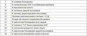
Pinout BN VAZ 2108, 2109, 21099
The fuel pump activation relay (2) is shown by an arrow.
1 — nozzles; 2 — spark plugs; 3 — ignition module; 4 — diagnostic block; 5 - controller; 6 — block connected to the instrument panel harness; 7 - main relay; 8 - main relay fuse; 9 — electric fan relay; 10 — controller power supply fuse; 11- electric fuel pump relay; 12 — fuel pump power circuit fuse; 13 — mass air flow sensor; 14 — throttle position sensor; 15 — coolant temperature sensor; 16 — idle speed regulator; 17 — knock sensor; 18 — crankshaft position sensor; 19- oxygen sensor; 20- APS control unit; 21 — APS status indicator; 22 — speed sensor; 23 — electric fuel pump with fuel level sensor; 24 — solenoid valve for purge of the adsorber; 25 — block connected to the ignition system harness; 26 — instrument cluster; 27 — ignition relay; 28 — ignition switch; 29 — mounting block; 30 — electric fan of the cooling system;
VAZ 2110 fuel pump pinout
If the fuel pump works directly when connected to the battery, then you will have to ring the wires going from it to the fuel pump relay, and if it does not work, then either replace it with a new one, or you will have to disassemble it and look for a fault inside the fuel pump.
Pinout BN VAZ 2113, 2114, 2115
— block headlights; — gearmotors for headlight cleaners*; - fog lights*; — ambient temperature sensor; - sound signals; — engine compartment lamp switch; — electric motor of the engine cooling system fan; — generator; — low oil level indicator sensor; — washer fluid level sensor; — front brake pad wear sensor; — wire tips connected to the common windshield washer pump**; — windshield washer pump; — headlight washer pump*; — wire ends for connecting to the rear window washer pump on VAZ-2113 and VAZ-2114 cars; — low oil pressure indicator sensor; — engine compartment lighting lamp; — wire lug for connecting to the wiring harness of the engine control system; — gear motor for windshield wiper; — starter; — a block connected to the wiring harness of the ignition system on carburetor cars; — coolant temperature indicator sensor; — reversing light switch; — low brake fluid level indicator sensor; - accumulator battery; — low coolant level indicator sensor; — relay for turning on fog lights; - mounting block; — brake light switch; — plug socket for a portable lamp; — hydrocorrector scale illumination lamp; — switch for the parking brake indicator lamp; — block for connecting a backlight lamp; — switch for instrument lighting lamps; - Understeering's shifter; - hazard warning switch; — front seat heating element relay; — ignition switch; — rear fog light circuit fuse; - fuse for the front seat heating elements; — door lock circuit fuse; — front ashtray illumination lamp; — ignition relay; - cigarette lighter; — glove box lighting lamp; — switch for the glove compartment lighting lamp; — heater fan electric motor; — additional resistor for the heater electric motor; — heater fan switch; - heater switch illumination lamp; — lamp for illuminating the heater levers; — gear motors for electric windows of the front doors; — power window switch for the right front door (located in the right door); — gear motors for locking front door locks; — wires for connecting to the right front speaker; — gearmotors for locking rear doors; — wires for connecting to the right rear speaker; — door lock control unit; — wires for connection to radio equipment; — headlight cleaner switch*; — rear window heating element switch; — relay for turning on the rear fog lights; — block for connection to the heating element of the right front seat; — rear fog light switch; — switch for the heating element of the right front seat; — fog light switch*; — switch for external lighting lamps; — left front seat heating element switch; — block for connection to the heating element of the left front seat; — wires for connecting to the left front speaker; — power window switch for the left front door (located in the left door); — power window switch for the right front door (located in the left door); — wires for connecting to the left rear speaker; — side direction indicators; — courtesy light switches on the front door pillars; — courtesy light switches on the rear door pillars; - lampshade; — ceiling lamp for individual interior lighting; — block for connecting to the wiring harness of the electric fuel pump; — trunk light switch; — instrument cluster; — trunk lighting lamp; — display unit of the on-board control system; - trip computer*; — block for connecting the wiring harness of the engine control system; — rear exterior lights; — rear interior lights; — pads for connecting to the rear window heating element; — license plate lights; — additional brake signal located on the spoiler.
Post navigation
Tip: Before doing this, slide the latches located under the dashboard. In addition, the problem may also be a failure of the distributor.
A problem can also occur when the VAZ wiring diagram operates with very high resistance, which will also lead to the formation of a weak spark.
There can be many reasons, as in the previous case, ranging from the failure of a particular device to wear and tear of the wiring or fuse box. The presence of sensors also modified the electrical circuit of the car - the VAZ wiring for the injector has many connectors for connecting sensors to the ECU.
Burnt contacts 3. Unlike the carburetor circuit, where the pedal directly controls the damper, in injection engines the pedal is not connected to the actuator; IAC idle speed regulator. Starter switch contact block. Limit switch for reverse gear lights.
A visual demonstration of troubleshooting is presented in the video. It is the electronic components in the VAZ injector that ensure uninterrupted operation of the engine, and if any element fails, the car will not be able to cope with its main duties. Fluid supply valve to the front glass.
Tips for high panel owners
Failed fuse box 2. There you can find in the photo detailed layout diagrams of the injector and ECU.
Most likely, the wiring has broken, the contacts on the generator have oxidized, or the drive belt is broken. Unlike a carburetor circuit, where the pedal directly controls the damper, in injection engines the pedal is not connected to the actuator; IAC idle speed regulator. If you have a VAZ injector with a low or high panel, then there is a possibility that the cause of the malfunction is the operation of the ECM. Did you like the article? Connection diagram for starter VAZ, VAZ, VAZ A - pull-in winding; B - holding winding; 1 - starter enable relay; 2 — mounting block; 3 — ignition switch; 4 - generator; 5 - battery; 6 — starter Fig.
Share with friends: You may also be interested. This car had a 4-door, 5-seater sedan body and a rear overhang extended by a mm. If the engine fails to start, the condition of the electrical circuits is first checked. Before you begin assembling the heater, be sure to lubricate the places where the dampers are attached with a special grease. One of the very first things to check is the DPKV for the serviceability of the connector and wiring. How does the cooling fan turn on?
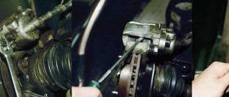
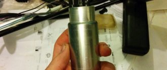
Replacing an electric fuel pump on a VAZ
- Reduce pressure in the fuel supply system.
- Using the fuel supply hose tip clamp, disconnect 2 hoses in turn.
- Unscrew the 8 nuts around the circumference of the clamping ring and remove it.
- A wire with negative polarity is attached to one of the nuts; it must be removed carefully.
- We take the electric pump block out of the fuel tank, tilting it slightly, to keep the fuel level indicator sensor lever intact, otherwise it will produce incorrect parameters.
- Remove the sealing rubber ring of the fuel block. If its properties are lost, the product must be replaced.
- Install the pump in reverse order.
When installing fuel hoses, focus on the direction of fuel supply indicated by the arrows, and the installation arrow on the electric pump cover should point towards the rear of the car!
Removing the low panel
Any liquid remaining in the radiator should be removed using a hose and funnel. In the places where the housing is connected to the radiator, bitoplast should be glued. You can dismantle the entire torpedo completely.
However, this is not at all surprising, because models with distributed fuel injection have numerous electronic devices built into them, which, unfortunately, can fail.
A typical sign of a discharged battery or poor contact of the power wires with the battery terminals. Electronic ignition The VAZ electrical circuit can be supplemented with a contactless switch; it is installed between the ignition coil and the distributor.
This charge is transferred through the wires to the switchgear, while the device continues to function. Fluid supply valve for the glass of the fifth door.
You will have to arm yourself with a socket wrench that fits the fastening nuts: push them inward, they can be removed later; you need to unscrew the air deflectors responsible for heating the side windows, located on the left and right sides; take a Phillips screwdriver and unscrew the screws securing the top cover to the surface; you can remove the external lighting regulator from the panel - for this purpose, pry it off with a flat object, for example, a screwdriver, and pull it out as long as the wiring allows; disconnect the power harness from the switch; we remove the radio with our own hands and take out the standard socket for radio equipment, if available; unscrew the central screw that secures the panel trim; That's it, you can remove the cover itself.
Next, you need to balance the fan impeller by winding wire around the blades.
A car produced from year to year in Belgium by Scaldia-Volga. Spark plugs. VAZ 2108 -09 -099 transition from carburetor to injector. part 2
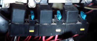
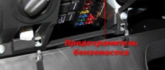
Where is the fuel pump relay located?
Where is the fuel pump relay located? The installation location of the relay varies depending on the make of the car. Most often, it is located under the hood, in the fuse and relay box.
The fuel pump relay is designed in the circuit to prevent accidental application of high voltage to the fuel pump winding. The relay is standard and consists of a plastic body and coils with contacts. It is located in the car interior near the console. To access it, you need to remove the protection cover.
In appearance, it is a small box that resembles a “plug” with an American type of output. Each terminal has a marking that indicates the following: 31 – mass; 30– +12V constant (regardless of ignition); 15– +12 with the ignition on; 50– +12 when the starter is running; TD – signal from the ignition system; TF – engine temperature signal from the injection control unit KE. Outputs: 87 – supplies power to the fuel pump; 87H – oxygen sensor heating; 87V – turns on the starting injector.
But sometimes the fuel pump does not turn on when the key is turned in the ignition. With what it can be connected? First of all, the fuse, although if it had blown, it would not work at all. Maybe the contact is bad?
If the electric fuel pump does not show any signs of life when the ignition is turned on, this does not mean that it has burned out. The cause of the malfunction may also be a relay. The easiest way to test your hearing is that when you turn on the ignition, the relay should click. If you don’t hear a click, there is a high probability that the “relay” is faulty.
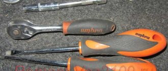
It’s easy to check the functionality of the pump itself, so we do this:
- remove the protective casing, under which there is a block with relays and fuses;
- we unscrew the fastenings of the block, remove it, it remains attached to the wires;
- we pull the RB out of the block, place a jumper between two opposite contacts, thus directly supplying power to the BN;
- if with such a connection the electric motor of the pump begins to make noise, it means that the BN itself is working, most likely the fault is hidden in the relay;
- if there is no voltage on any of the contacts on the RB block, you should look for a break in the wiring; there may also be poor contact at the place where the wire is attached to the terminal.
Tips and tricks
It should be noted that before purchasing a gasoline pump, you must carefully study its characteristics in terms of performance and pressure, current consumption, etc. In some cases, a situation may arise when the device is not able to work normally with a particular carburetor.
We also recommend reading the article on how to clean the fuel pump filter mesh with your own hands. From this article you will learn about methods for disassembling a fuel pump to remove the strainer, as well as how and how to clean the fuel pump strainer. For this reason, it is necessary to take into account all possible nuances in advance. It is advisable that there are already examples of successful installation of a particular pump on a similar car. You also need to pay attention to the fact that installing an electric pump obliges the owner of a car with a carburetor to additionally monitor the cleanliness of the fuel filters.
The fact is that clogged filters increase the load on the pump, as a result of which the device may overheat or fail. As a rule, in case of problems with filters, first the pump’s performance drops, then the engine may begin to work unstably, power is lost and traction deteriorates. Ignoring these symptoms not only makes it difficult to operate the car, but also significantly reduces the service life of the electric fuel pump.
Sources used:
- https://2shemi.ru/raspinovka-i-shema-benzonasosa-s-rele-vaz/
- https://masteravaza.ru/sistema-pitaniya-dvigatelya/benzonasos-sistema-pitaniya-dvigatelya/elektrobenzonasos-vaz-2110-618
- https://krutimotor.ru/elektricheskij-benzonasos-na-karbyurator/