Electrical package control unit in Priora
The car electrical package controller is a unit responsible for the functionality of the car.
The node regulates the operation:
- electric window lifts;
- main panel backlight;
- functioning of turn signals;
- side and fog lights;
- rear lights;
- heated rear view window.
All these devices must work clearly and harmoniously. Since the safety of the driver and passengers during the trip largely depends on them.
Also, the control unit for the Priora electrical package adds additional convenience to the driver in driving the vehicle. Hence its running name “comfort block”.
Priora electrical package control controller | PrioraPRO
Lada Priora (VAZ 2170) is one of the few domestically produced cars equipped with such a multifunctional device as an electrical package control controller. However, what is it and what controller is on the Priora?
The power package controller is a device that controls all of the vehicle's electrical functionality. Thus, this regulator is responsible for the operation of the turn signals, power windows, instrument panel lighting, side lights, fog lights, interior lighting, heated rear window, and reversing lights. Equipping a car with such a control unit makes it more practical in terms of using electronics.
The electrical package control controller on the Priora is mounted using brackets in the central, lower part of the dashboard above the engine control unit (ECU). On the Lada Priora, the controller is connected via two connectors: the power connector is responsible for supplying energy to the control unit, and the information connector is responsible for its direct functions. Also, the unit is equipped with protection from moisture and dust.
Essentially, the Priora electrical package controller is a circuit in a plastic case. The board itself (circuit) consists of 15 chips, each of which has its own purpose.
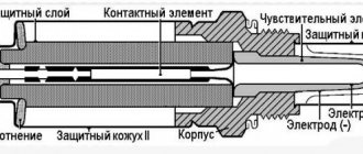
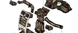
Purpose of parts on the board of the Priora electrical package control unit 2170-3763040.
Diagram of the Priora electrical package control unit 2170-3763040.
POS - interior lighting; ZPTO - rear fog lights; BS - low beam; PTF - fog lights; MDV - driver's door module; PUP - turn signal switch; PAS - hazard warning switch; PPD - front right door; PLD - front left door; ZPD - rear right door; ZLD - rear left door; PS - passenger door power window switch; POB - trunk light; ZP - right mirror; ZL - left mirror; GO - side lights; UP - direction indicators.
The pinout of the electrical package controller on a Priora car is an electrical process, the complexity of which is explained by the versatility of the unit. In this regard, many wires of different functionality are connected to the controller - the unit is connected by more than 25 wires.
The machine electronics control unit has several operating conditions:
- air temperature from -45°C to +40°C;
- atmospheric pressure up to 800 mm Hg. or 105 kPa;
- air humidity up to 90%;
- operating voltage range from 9 to 15 V.
Failure of the electrical package controller may be caused by overheating of the system or disconnection of wires. In this case, it is necessary to inspect the control unit itself. On a Lada Priora car, the controller is located above the engine, and in case of malfunction or interference, it will be necessary to remove the dashboard.
Comfort block functionality
The main functions that the comfort unit contains are electrical control in the car. Since the list of tasks performed is extensive. Malfunctions in the operation of the unit can seriously harm the driver, especially during dense traffic around the city.
Comfort block tasks:
- turn signal indication;
- car interior light;
- fog lamps, low beam lights, parking lights;
- electric double glazing unit;
- side mirrors operation, adjustment, heating;
- anti-theft mechanism;
- door blocking;
- security alarm;
- luggage compartment lighting;
- dashboard lighting.
Each of these functions is essential for a car. Therefore, excluding even one of them from work will bring significant inconvenience to the driver.
Location of the comfort block in Priora
In order to get to the comfort unit, you need to remove the plastic cover of the central panel of the machine. It is located between the driver and passenger seats, to the right of the gas pedal behind the bottom of the partition.
Voltage is supplied to the control unit through the main connector. And the secondary connector is responsible for performing functions.
The unit is protected by a casing from the penetration of moisture, dust and foreign bodies. The board itself is a set that holds 15 chips. Each chip is responsible for its own function, such as adjusting mirrors, power windows or opening doors.
To access the comfort block, you need a Phillips screwdriver and a 10mm wrench. After disconnecting the connectors, you need to remove the bolt and nut and remove the block itself.
pinout, electrical package control controller and circuit
Almost all modern cars today are equipped with electric windows, which allow you to control the opening of the windows at the touch of a button. And the Russian Priors in this case are no exception. The control device, with the help of which the windows are raised and lowered, as well as many other functions, is called the Priora comfort unit. You can learn more about its structure, as well as repair, from this article.
Description of the electrical package control unit
The electrical package controller in Priora is a device used to control the functionality of the vehicle. This unit is responsible for the operation of turn signals, power windows, control panel lighting, dimensions, fog lights, interior lighting, and rear window heating system. This device also ensures the normal operation of the reversing lights. The fact that the car is equipped with this device makes it even more practical.
Location
The control device on the Priora is located above the electronic engine control unit, at the bottom of the center console, in the middle. In this case, the device is connected using two connectors - power and information. The power output is used to supply voltage to the control unit, and the information output is used to perform the functions of the device. It should also be noted that the control unit is protected from external influences of dirt and moisture.
Location on newer models
Once you have disconnected the negative terminal from the battery and made the disassembly process safe. Disconnect the decorative protective cover located under the steering column. To do this, you need to release three mounting fasteners using a 10mm wrench.
In this case, the comfort block is located behind the mounting block. And you will have to act by touch, which is what car mechanics are used to doing.
Before removing the unit, you need to disconnect the three electrical harnesses from the wires. The fastening mechanisms should not be unscrewed completely. But only turn it 3 or more turns, since they have an open circuit. Then you can remove the block itself.
Electrical unit pinout
The elements included in the electrical unit package are divided into the following components:
- drivers, each of which has its own function and is responsible for a separate section;
- relay coordination;
- transponder receiver;
- the transceiver is involved in the connection with the door module;
- two connectors for transmitting electricity and necessary engineering information.
When familiarizing yourself in detail with the diagram of the distribution of wires by numbers (pinouts). Working with the Priora comfort unit will not be particularly difficult.
Each contact in the diagram is described separately, which is important for understanding all operational problems. The Lada Priora comfort block diagram is present in the technical manual for the car.
Download pdf
VAZ 2170 Lada Priora. Electrical equipment diagrams.
VAZ 2170 Lada Priora. Electrical equipment diagrams.
Lada Priora_electrical circuit diagrams
To enlarge the images, click on the image, it will open in full resolution.
Diagram 1. Instrument panel harness connections:
1, 2, 3
– pads of the instrument panel harness to the front harness;
4
– instrument panel harness block to the rear harness;
5
– contacts of the mounting block;
6
– brake light switch;
7
– instrument cluster;
8
– lighting control module;
9
– driver airbag module;
10
– sound signal switch;
11
– diagnostic block;
12
– on-board computer mode switch;
13
– ignition switch (lock);
14, 15
– blocks to the electric amplifier control unit;
16
– electrical package controller;
17
– light signaling switch;
18
– windshield wiper and washer switch;
19
– gearmotor for air flow distribution;
20
– heater control unit;
21
– heater electric motor switch;
22
– rear window heating switch;
23
– hours;
24, 25
– connectors for the instrument panel harness to the radio equipment;
26
– alarm switch;
27
– lampshade lighting of the glove box;
28
– glove box lighting switch;
29
– block of the instrument panel harness to the harness of the electronic engine management system;
30
– airbag system control unit;
A1, A2, A3
– grounding points of the instrument panel harness;
B
– mounting block block.
Diagram 2. Vehicle front wiring harness connections.
1
– starter;
2
– battery;
3
– generator;
4
– blocks of the battery harness, starter and front harness;
5, 6, 7
– front harness pads to the instrument panel harness;
8
– engine compartment lamp switch;
9
– left headlight;
10
– right headlight;
11
– brake fluid level sensor;
12
– air temperature sensor;
13
– electric motor for washers;
14
– reverse light switch;
15
– engine electric fan;
16
– heater damper gearmotor;
17
– additional resistor;
18
– windshield wiper motor;
19
– main fuse block;
20
– heater electric motor;
21
– alarm signal;
22
– sound signal;
A1, A2, B1, B2
– grounding points of the front harness.
Diagram 3. Engine Electronic Control System (ECM) Harness Connections.
1
– ECU;
2
– ECM harness block to the instrument panel harness;
3
– main fuse block;
4
– speed sensor;
5
– rough road sensor;
6
– warning lamp sensor for emergency oil pressure drop;
7
– throttle position sensor;
8
– coolant temperature sensor;
9
– coolant temperature indicator sensor;
10
– mass air flow sensor;
11
– idle speed regulator;
12
– electric fuel pump relay;
13
– fuse for the electric fuel pump power supply circuit (15 A);
14
– ignition relay;
15
– ignition relay fuse (15 A);
16
– ECU power supply fuse (7.5 A);
17
– crankshaft position sensor;
18
– control oxygen concentration sensor;
19
– phase sensor;
20
– knock sensor;
21
– solenoid valve for purge of the adsorber;
22
– diagnostic oxygen concentration sensor;
23
– ignition coils;
24
– spark plugs;
25
– nozzles;
26
– block of the ignition coil wiring harness to the ECM harness;
27
– ECM harness block to the ignition coil wiring harness;
28
– ECM harness block to the injector harness;
29
– injector harness block to the ECM harness;
A
– to the “plus” terminal of the battery;
B1, B2
– grounding points of the ignition system harness;
C1
is the grounding point for the ignition coil wiring harness.
Malfunctions in the operation of the comfort unit, how to eliminate them
- The turn signals do not light up. First, you should check the continuity of the fuse, lamps and steering column switch. If there is simply no contact somewhere, then the problem can be resolved very simply by resoldering the microcontacts. If there is a fault in the board itself and soldering the contacts does not help, then the controller should be replaced.
- The power window module or central locking does not work. This problem can also occur due to oxidation of the wires. Before removing the comfort unit, you need to check all the wires with a multimeter under the insulation in the control unit, which is built into the driver's door. If only one glass unit is faulty, the wires could become disconnected due to a broken contact.
After checking the wires, if the problem cannot be found. The DA7VN5016A or DA6VN5016A controller should be re-soldered. One of them is responsible for the double-glazed windows and the lock on the right door. The second mirrors the same functions, but on the left side.
The relay that sends information to the lifts is contained in the DA11L9848 controller. Often errors can be present here. Everywhere in the block at the outputs the numbering of wires is clearly written for correct connection.
Sometimes window lifters only work to lower the windows, but raising them is not available (or vice versa). To do this, check the connection so that all the pros and cons are in place.
Errors occur in the comfort unit when the window lift button to raise the window works to lower the window. With different polarities, when the glass rises instead of lowering, you need to change the connection of two adjacent wires.
- It happens that many problems arise at the same time. The fog lights, side lights, rear lights, heated rear glass, and interior light stop working. In this case, it is obvious that the problem comes from the comfort unit and the DA1 MC33972EW variant is re-soldered. If this does not help, then the entire circuit should be replaced.
- In case of failure of the rear fog lights and instrument lighting in the cabin, the DA9 VND5025AK component is re-soldered. And, as was the case with previous breakdowns. If this does not bring results, the entire scheme is changed.
- The central locking locks begin to operate when the power window keys are pressed. If replacing the comfort unit from another car does not bring any effect, then the essence of this breakdown is in the wiring. To do this, you need to carefully check the integrity of all wires leading to the comfort unit.
Possible causes of malfunctions
Before purchasing a new comfort unit, you need to try to eliminate any malfunction. In order not to make additional costs, because the comfort unit is quite expensive. Often the problem is simply a lack of contact due to aging or chafing of the wires.
Sometimes the comfort unit controllers can burn out, for this you need to inspect them visually or even check them using your sense of smell.
The most common complaints regarding the operation of the comfort unit are the failure of double-glazed windows, turn signals or dimensions.
All problems can occur due to the following events
- break on the W-Line communication line;
- combustion of regulation drivers;
- burnout of controllers responsible for the desired area;
- transponder malfunction;
- burnout or oxidation of contacts.
Before carrying out repair work, to comply with safety precautions, do not forget to disconnect the negative terminal from the battery.
How to disarm the electrical package unit of LADA PRIORA
What to do if Priora is not removed from the standard alarm!
The hazard warning light blinks, the car does not respond to the ignition key buttons. As a rule, several units are involved here that are synchronized with each other.
- Ignition
- Radio channel module (Located in the driver's door)
- Electrical package block (Comfort block)
- Engine ECU
New blocks come with non-activated codes inside and can be installed on any car without problems, but once you register (train) the keys, a special code is written into all these blocks, which is synchronized with each other and serves as a standard alarm system. (Immobilizer) As soon as you turn the ignition key, within five seconds there is a poll between the key and the units, if the code matches everywhere, then the engine ECU gives permission to start, if the code of at least one device is not recognized, the engine ECU is blocked and the car does not start.
Training a working key is done using a special red training key. I will not describe the procedure for training keys; there is plenty of information on the Internet. In fact, the main key is a red training key; it stores a code that, after training, is written into the working key and other blocks.
I'll try to explain in more detail how it all works:
- The radio channel code that we use to open doors using the key's remote control buttons is written into the driver's door module, where the power window buttons are located. If you replace the comfort unit or engine ECU, the buttons on the key will still work.
- The IMMO (Immobilizer) code has a connection only with the ignition key, the electrical package unit and the ECU unit. If you disconnect the driver's door module, the car will still start.
How to determine whether the keys are trained or not:
- The IMMO lamp on the instrument panel goes out after 5 seconds - the keys are trained.
- The IMMO lamp goes out after 30 seconds - the keys are not trained. (The car will start with any blank)
Repair and replacement of the comfort unit
To begin repair work, you should make sure that the problem with the malfunction lies specifically in the electrical unit of the car. Alternatively, you can install a working unit in the machine and check the correct functioning of the problematic paths.
If with the new block all functions of the machine work without malfunctions, then the problem lies in the block. Before removal, check the integrity of the wires and fuses. And only then does work begin with the comfort block according to the following algorithm.
- install the car on the handbrake;
- for safety, disconnect the negative terminal;
- for the comfort of repair work, move the front seats back to free up the necessary space;
- remove the fasteners and remove the side casing;
- the fastening nuts are removed using a 10mm wrench;
- The block should be removed carefully, without damaging it on the casing walls or other elements. The two connectors (power and information) available in the block should be disconnected one by one.
A new one is installed in place of the faulty unit. In case of repair of the unit (such as re-soldering of individual controllers), it is installed in place after completion of the repair work. To carry out resoldering, the protective housing of the comfort unit is removed.
If you are installing a new unit, keep the purchase receipts until it is fully tested and in working condition so that you can return it in case of a possible malfunction.
For convenience, the unit is equipped with multi-colored wires to simplify the work of disconnecting and connecting. When weaving from the comfort block to the door, all wires must match in color.
After you have repaired the unit and connected it, you should check the operation of the windows, mirrors, lights, etc., then hide the wiring behind the car panels.
At the end of the work, all the wires are successfully hidden behind the carpet and thermal insulation. Therefore, this type of work will not affect the visual appearance of the salon.
Repairing the comfort unit on Priora yourself
If you did not have the skills to work with a soldering iron and similar electrical circuits before this repair. The best solution would be to forward this problem to an electrician at a service station. This type of work is labor-intensive and requires certain skills.
If you have already encountered similar problems and have experience in such work, then replacing these microcircuits is often done by car enthusiasts themselves. With the presence of a programmer, the data of some of the circuits can be re-registered, but this is a technically more complex process.
When using the master key, the control unit may go into emergency mode and the unit may be locked. For this type of work, you need to reset the control unit and erase errors.
Lada Priora Sedan Handmade › Logbook › Electrical package control unit (Itelma) 2170-3763040
a month ago the electrical system partially failed.
Refused: - opening the trunk with a button - heating the left mirror - adjusting the left mirror (partially, 2 directions worked) - left ESP - Lock (activator) of the left door. After a short investigation of the unit, it turned out that one of the control chips (driver) had burned out.
mikrukha marking - VN5016A - mikrukha is not very popular in radio components, they are not available. — There are different markings: VN5016A (the one that burned out had one), VN5016AJTR-E (I bought one), vn5016aJ-E (I had it on a diagram I dug up on the Internet, if necessary I can send it) — Cost from 80 to 200 rubles. I bought it at Voltmaster for 120 rubles. You can order it freely from China, but in large quantities.
Regarding soldering, you can re-solder it at any electronics repair service (it will cost approximately 200 - 800 rubles). I decided to solder myself, because... I had a soldering iron and a hair dryer, and I didn’t have much experience. But even here there were some incidents, I overheated the elements lying around and brushed them off a little, I had to solder them back in from memory.
As a result, I spent a total of 300 rubles, but saved 3500 (new module) + 1500 (diagnostic services and ECU flashing) = 5000 rubles
As for this malfunction with the electrical components, it is a prior disease, judging by the discussions on the forums, and there are no clear reasons.
The result is everything works properly, my mood is up, I’m as happy as an elephant! Thank you everyone, Peace to everyone!
Correct conditions for using the comfort block
Often, the breakdown can be determined immediately. Simply by performing an external inspection of the comfort unit. You can visually see contacts that have come loose due to mechanical damage or overheating.
For the structure to operate in normal mode, the operating range must correspond to the following parameters:
- mercury pressure – up to 800 mm;
- voltage range – 9-15 volts;
- permissible humidity in the cabin – up to 90%;
- the temperature in the cabin is from minus 45 to plus 40 degrees.