What causes the Chevrolet Niva ECU to fail?
The Chevrolet Niva ECU may fail for the following reasons:
- Unqualified intervention in the car's electrical system, for example when installing an alarm system.
- Turning on the starter when the power bus is disconnected
- Lighting a cigarette from a car with the engine running
- Contact of the electrode during welding work with sensors or the ECU device itself
- Reverse polarity when connecting the battery
- Water entering the ECU and ECM
- Removing the battery terminal while the engine is running
- Malfunction of distributor ignition coil, etc.
Diagnostics of the Chevrolet Niva ECU involves reading errors recorded in the controller’s memory. Errors are read using special devices: a computer, a loop through a special K-line. You can also get by with an on-board computer that has the function of reading ECM errors.
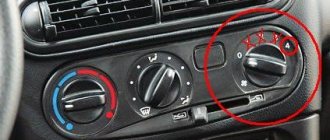
Chevrolet Niva Quartz Turbolux › Logbook › Redesigning the fan switching circuit (part 2).
In order not to refer to the coff page every time, I will copy here the modification scheme and its original description in italics
with my additions and comments:
0. So, for starters, be sure to!
disconnect the ground wire from the battery. Our relays have contacts under constant voltage, and since all this will have to be done in an awkward position under the glove compartment and next to metal parts, you can easily make a short circuit.
1. Remove the glove compartment lid
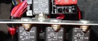
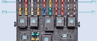
, having pulled out the two plastic axles and unhooked the limiting cables, unscrew the nut and remove the casing covering the brains. We get this picture.
2. Relays 6 and 8 are replaced with 5 contact ones.
We will do this later, at the end of the build.
3. Between leg 88 of relays 6 and 8, place a jumper.
A jumper between the NO contacts (88 according to the new circuit or in real life between contacts 87a) of our new relays. The wire must withstand at least 10 A. I got it like this:
4. On relay 8 we swap red 30 and pink black 87.
A small digression. The terminal in the standard relay block is held in place by a bent iron tendril (on the terminal itself) on one side and a plastic spring protrusion in the block itself on the other side. This differs from the factory block from many individual blocks sold in stores. In them, as a rule, contact is maintained only by the antenna on the terminal. Accordingly, in a regular block we bend the spring contact (from the connector side) with a thick needle or a narrow clock screwdriver and the terminal can be pulled out. This does not work with a standard block. In addition to pressing out the spring contact, you also need to use an awl or a narrow screwdriver to tighten the plastic contact of the block. Most often this is easier to do by inserting a screwdriver into the terminal from the wire side. If the contact does not pull out, do not use excessive force - you will simply break or tear off the terminal. Of course, it’s easier to use special pullers, but if you don’t have them, then you can get by with thin screwdrivers. I used these from a cell phone repair kit:
5. On relay 6, cut off the red 87 and connect it to ground.
We cut through the thick red wire (about three centimeters in length from the block). We isolate the part that goes into the wiring harness. We remove the terminal remaining in the block and splice it with a thick (no less than the thickness of the red wire) wire with a round terminal. The current on this wire can already exceed 25 amperes.
As I already said, the current through this wire can reach 25 amperes and if the ground contact is poor, there can be local overheating in this place (you need to check the heating at the second speed of the fans).
6. Swap the pink wires of relay 2 87 and relay 6 30.
Handle the contacts carefully - do not break the terminals, although if you have already successfully removed the previous ones, there will be no difficulties.
7. Collect everything.
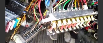
We assemble the pads if they were disengaged. We put all the relays in place and try to put everything back together as it was. Here an oops was waiting for me. Let's look at the photo.
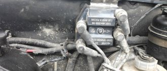
8. Open the hood, on top of the radiator we see a harness going to two fans and an additional resistor, unwind the end of the harness.
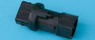
9. Cut off the wires from the additional resistor block. There are 2 pink wires.
10. We call them with the right fan block (passenger side)
I rang even before cutting (photo a little earlier) directly on the removed blocks of the fan connector and the additional resistor connector. I marked the necessary wires, after which I finally bit off the resistor block and inserted the fan connector back into place.
11. We isolate the pink one from the resistor and isolate it from the pink fan.
The unwound end of the harness.
12. Cut off the brown wire going to the fan. We isolate the part that goes into the harness. 13. We connect the remaining pink resistor with the additional resistor, the one that did not ring, to the brown wire on the fan.
14. We isolate and check everything.
Here's what I ended up with:
The remaining wires in the additional connector plug. I also insulated the resistor and put the connector back in place. It is no longer needed, but removing this resistor and wiring is a chore - I didn’t bother. If you ever have to disassemble/take out the fans, you can finally remove the plug and wire and the resistor itself.
I can recommend doing test tests of the resulting circuit before final assembly and insulation of the wires, so that you can, if anything, redo everything again without unraveling.
We put the ground terminal on the battery and try. Everything worked for me the first time. I checked the operation of the fans with the air conditioner and at first speed. I couldn’t heat it up to the second (they suggested that I had to remove the chip from the fan on the driver’s side, then the first speed would not turn on. It would also be possible to change the channel for turning on the fans from the BC and set the temperature to 90 degrees to check).
You can diagnose a faulty Chevrolet Niva ECU using the following symptoms:
- Lack of control signals for injectors, ignition, fuel pump, valve or idle mechanism, as well as other actuators
- Lack of response to Lambda - regulation, temperature sensor, throttle position sensor,
- No communication with diagnostic tool
- External damage (burnt radio elements and semiconductors)
If your assumptions and the Chevrolet Niva ECU are faulty, it is urgently necessary to replace it.
Where is the Niva Chevrolet engine control unit located?
Repair and service of cars, engines and automatic transmissions
Components of the Chevrolet Niva engine management system
The VAZ-2123 engine installed in a Chevrolet Niva all-wheel drive vehicle is equipped with a distributed phased fuel injection system: gasoline is supplied by injectors to each cylinder in turn in accordance with the operating order of the engine.
Programmable read-only memory is non-volatile, meaning the contents of its memory do not change when the power is turned off.
The controller detects the presence of malfunctions in control system , turns on the malfunction indicator in the instrument cluster and stores fault codes in its memory.
Chevrolet Niva engine management system malfunction indicator is located in the instrument cluster.
The only exception is the crankshaft position sensor; if it is faulty, the engine cannot run.
Where is the ecu in the Niva Chevrolet? and how to determine which ecu is installed
Engine control unit location
on
a Chevrolet Niva
2006, there are also located: Additional relay.
Chevrolet Niva ECU Tuning
Removal of ECU and CHIP tuning of Chevrolet Niva using Tula Scanmaster CAN programmer.
Based on the number and frequency of these pulses, the controller calculates the phase and duration of the pulses to control the injectors and ignition coils.
The operating principle of the phase sensor is based on the Hall effect. A metal adjuster is riveted to the camshaft sprocket.
The sensor is a negative temperature coefficient thermistor, meaning its resistance decreases as the temperature rises.
The piezoceramic sensing element of the sensor generates an alternating current voltage signal, the amplitude and frequency of which correspond to the vibration parameters of the engine cylinder block wall.
The controller calculates the duration of the fuel injection pulse based on parameters such as air mass flow, crankshaft speed, coolant temperature, and throttle position.
The design and operating principle of the diagnostic sensor are the same as that of the control oxygen concentration sensor.
The sensor provides the controller with rectangular voltage pulses (lower level - no more than 1.0 V, upper level - no less than 5.0 V) with a frequency proportional to the wheel speed.
bracket under the instrument panel console screen on the left side.
The four-terminal ignition coil is a unit of two coils. The coil is mounted on a bracket mounted on the left side of the cylinder block.
Spark plug wires are connected to the terminals of the secondary (high-voltage) windings of the coil: to one winding - the 1st and 4th cylinders, to the other - the 2nd and 3rd.
The gap between the electrodes is 1.0–1.1 mm. engine management system relay and fuse box is attached to the controller bracket.
One of the 50 A fuses protects the power circuits of the right fan and the additional relay, and the other protects the power circuits of the left fan.
Source:
Where are the main relays and ground located on the Niva Chevrolet
All main modules of the car are driven by one or another control circuit. They serve not only to transmit power, but also allow you to read information from a large number of sensors, which is subsequently decrypted by the electronic control unit. This allows the engine to operate at its optimum.
How to replace a Chevrolet Niva ECU with your own hands - step-by-step instructions.
The engine control system fuses are located in the control system fuse and relay box, located on the rear cover of the controller under the instrument panel on the bulkhead in front of the passenger. You will need a “10” wrench (preferably a socket).
Replacing the ECU on a Chevrolet Niva occurs as follows:
- Unscrew the nut securing the controller cover and remove the cover.
- Remove the fuse and relay box cover
- Remove the left and right screws securing the controller and fuse and relay box to the bulkhead.
- Move the controller away from the front panel, unscrew the two nuts securing the block to the controller and separate the controller from the block.
- Move the wiring harness block latch aside and disconnect the block from the controller.
- Install the controller and fuse and relay box in the reverse order of removal.
Device comparison
The term “firmware change” is popular among car owners. Let's take a closer look at what happens when you try to change the “brains” on a Chevrolet Niva. We will conditionally divide all tuning work into two categories. The first involves changing the software without changing the control unit itself. Everything is simple here, because this software is developed directly by the manufacturer. In later versions, errors are eliminated and the computer's adaptation to the driver's actions is improved. To change the software, you will need a laptop, a cable with an adapter, and the corresponding software on your computer.
What is good about the method of software correction of internal combustion engines compared to other options?
niva board In practice, the most effective indicators of ICE tuning are shown by the following methods:
The first two methods require significant capital investments, as well as time costs: the engine must be dismantled, additional equipment must be installed, or certain modifications must be made. A completely different approach is needed when chip tuning a Chevrolet Niva car engine, when any intervention in the mechanical part of the power unit is not required. It is enough to carry out full diagnostics and adjustments of software components.
Most reviews from car owners about this procedure are contradictory, but almost all of them highlight a number of its advantages:
The tuning process for professionals takes on average about 30 minutes. The price line for work performed starts at 2,000 rubles.