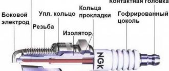
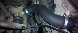
Where did all this even start? Yes, because one day after work I started the car and realized that it was a complete mess. I opened the hood and looked. I think we need to check which cylinders are working. I take the wire of the first cylinder. And then the machine gave me a thousand pricks from the discharge that this wire emitted... Everything is clear, it breaks through. Having warmed up to 40 degrees, the tripping disappeared o_O. Ok, you can live. went home. I started thinking about what to do with the wires that I bought a year and a half ago. "Elephant". I looked at how much new ones cost - 900 or more, silicone wires. Hmm...a little expensive.
I started digging into the drive. And then I remember that I saw an article about homemade explosive wires. 1 minute in Google and 15 articles on the drive are ready to read. Someone makes it from ZIL wires, there is a copper core - the resistance tends to 0. Someone makes a corrector vacuum from acoustic wires and silicone hoses. I settled on this decision. The article that I took as the BASIS! Special thanks for the advice Stuff0rd McSystem
What we need: — MGTF wire -0.35mm 2 meters (enough almost point-blank). (I came across this brand of wire by accident in the comments) I read that the cross-section is not so important as the insulation of the wire, and that 0.2-0.5 cross-section is enough for the eyes. — Silicone vacuum corrector hoses 3 pcs. — Heat shrink 8mm (more than the diameter of the hoses) — 2 meters. - BB wires. - VDeshka - Someone’s mother... (Required!)
1. First, we take the old (or the only ones - like I did) wires and begin to disassemble them. I simply pulled the terminal on the spark plug side out of the insulator. It's hard but it works out. But the corner terminal must be carefully disassembled and the wire pushed towards the terminal so as not to damage it. Since I also pulled out the first one by force and almost broke it at the bend))
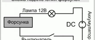
The procedure for connecting high-voltage wires on a VAZ 2109 (carburetor, injector)
The ignition module on injection VAZ 2109 is deservedly considered one of the most complex electrical components. If the injectors have a module, then the carburetors have the simplest coil.
The actual, but incredibly important task of the module is the generation of high voltage current, which can reach 30 thousand watts. The current follows high-voltage wires to the spark plugs, which create a spark to ignite the air-fuel mixture.
The classic ignition coil is one of the components of the module, so the system works on a much more complex principle than on carburetors.
What are the armored wires for the VAZ 2112 needed for and what functions do they perform?
Expert opinion: The main task of the high-voltage wires of the ignition system of gasoline engines is to transmit the ignition pulse from the coil (coils) or ignition distributor to the spark plugs of the internal combustion engine.
Along with this, the high-voltage wires on the VAZ 2112 car perform the following functions:
- ensuring high-quality isolation of high-voltage pulses;
- minimizing radio interference;
- protection against failure of ignition system elements.
If the electrical parameters of the high-voltage wire are violated, the car engine begins to “triple”, there is a large loss of car power, and the car’s starting system may fail. Such a malfunction must be corrected immediately, as it can lead to a complete failure of the ignition system, malfunction of the vehicle’s mechanical components due to uneven engine operation.
New armored wires for VAZ 2112
High voltage wires
Often, the main difficulty when repairing a carburetor VAZ 2109 is the reconnection of high-voltage wires that were previously disconnected from the distributor cover. It's also an ignition distributor.
The difficulty is that many people forget the connection procedure or simply do not know. But in practice, returning high-voltage wires is much easier than understanding the ignition module used on the injection VAZ 2109.
By following a few simple rules, you can easily return the wires to their rightful places.
- The ignition distributor cover is installed in its place, that is, on the distributor, only in a single position. Therefore, even if you wanted to, you won’t be able to confuse anything here. Otherwise the lid simply won't fit.
- There is an installation mark on the cover, which indicates the location of the wire socket from the first cylinder.
- The wires must be connected in the following sequence - 1, 3, 4, 2. Move counterclockwise when looking at the distributor cover from the side of the expansion tank.
If for some reason there are no installation marks on the VAZ 2109 carburetor distributor cover, just follow the connection principle shown in the image.
Connection diagram of VAZ 2112 armored wires to the ignition coil
Injection VAZ produced before 2004 with an old-style ignition module (4-pin low-voltage connector)
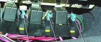
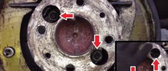
Actually, on the module body it is already indicated which cylinder the pins correspond to - but we duplicated them in red in case the module gets completely dirty, and you might not be able to see it in the photo.
Injection VAZ produced after 2004 with a new ignition coil (3-pin low-voltage connector)
As with the old-style ignition modules, the new coils are also marked with pins corresponding to the cylinders. But the connection order is different from the order on the old-style ignition module. Be careful!!!
Features of the ignition module
Now let's talk about a more complex issue - the ignition module and its design features.
The design includes several components, each of which has its own nuances.
Component
Peculiarities
There are always two coils on a VAZ 2109. This mechanism is responsible for generating current
Switch keys also work together. Through them, the current goes to the spark plugs, plus the controller regulates the time the current is turned on, which is calculated by receiving information from the crankshaft sensor
Electronic control unit
Responsible for distributing information in the form of electronic impulses
High-strength plastic is used for its manufacture, which largely ensures the durability and reliability of the device.
Ignition coil
Location
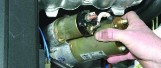
Any work related to repair, testing, and maintenance of the ignition module will be impossible to perform if you do not know basic things - the location of the device.
You can find the ignition module (ignition module) in the engine compartment. Find the high voltage wires that go to the spark plugs. One end is connected to them, and the other goes to the module. The MZ is small in size and enclosed in a plastic housing.
Device location
Principle of operation
Initially, on carburetor cars, the system worked due to the presence of an ignition coil. With injectors everything is somewhat different.
- Initially, the ignition coil is turned on, generating a high voltage current. The coil operates on the principle of magnetic induction;
- Then the electronic control unit MZ is connected to the work, performing the functions of control, transmitting commands, and ensuring the flow of current required by the characteristics to the spark plugs;
- Next, the spark plugs activate the spark, ignition occurs, and so on.
MH malfunctions
The ignition module often shows the most basic sign of failure - lack of spark. But this is not the only indicator of a malfunction. These also include:
- Lack of dynamics when accelerating the car. Trying to quickly pick up speed, you can clearly feel failures in engine operation;
- The engine does not produce the usual power; in some cases, the engine is not able to pull the car uphill;
- The idle speed fluctuates;
- One of the pairs of engine cylinders refuses to work. Here, most likely, there is no current that should come from the ignition coil.
Firing order
The cylinders in a car do not work chaotically, because for stable operation of the engine and alternate execution of all four strokes, their strict synchronization is required.
So there is a special order of operation of the cylinders of the VAZ 2114, thanks to which each of them at one point in time performs any of 4 strokes, namely:
- Injection of a mixture of fuel and air that fills the entire volume of the cylinder.
- Compression of the working mixture due to the upward movement of the piston.
- The combustion of the working mixture and the expansion of the resulting gases pushes the piston in the opposite direction, thereby driving the connecting rod and crankshaft.
- The release of exhaust gases from the cylinder with their further discharge into the exhaust system.
Armored wires and their connections
Having found out how the location of the VAZ 2114 cylinders affects their connection, it is worth talking about the high-voltage wires with which this is done.
These wires themselves are quite different from ordinary electrical wires - they have an increased layer of insulation, protective shielding, as well as metal connecting tips and protective caps made of heat-resistant plastic. The main purpose of these wires is to transmit a high-voltage pulse from the ignition unit to the cylinders (it is this pulse that allows the spark plugs to ignite the working mixture).
The connection of armored wires should be made taking into account the ignition order of the VAZ 2114 injector and the numbering of the cylinders (this was mentioned above). For greater convenience, you should be guided by the numbering present on the ignition module - just connect socket number 1 to the corresponding cylinder, socket number 2 to cylinder number 2, etc. It is extremely difficult to make any mistake here.
Do-it-yourself replacement of armored wires on a VAZ 2112
1 – tip of the wire of the first cylinder; 2 – tip of the wire of the second cylinder; 3 – tip of the wire of the third cylinder; 4 – plastic bracket securing the high-voltage wire of the third cylinder; 5 – ignition module; 6 – tip of the wire of the fourth cylinder; 7 – plastic bracket for fastening high-voltage wires of the first, second and fourth cylinders
In order to replace the armor wires of a VAZ 2112, you must perform the following procedure:
- We prepare the car for work (see “Preparing the car for maintenance and repair”) and turn off the ignition.
- Remove the engine decorative trim.
- Remove the wire tip from the spark plug well.
- Disconnect the other end of the high-voltage wire from the ignition module.
- Remove the wire from the first cylinder.
- Similarly, we remove the high-voltage wires of other engine cylinders.
High voltage wires are not interchangeable. The wires must be connected to the ignition module in accordance with the cylinder serial number
How to choose high-voltage wires
When choosing new high-voltage wires for your car, you should be guided by their two most important parameters - resistance and breakdown voltage. So, the less resistance the armor wire core has, the better it will transmit the impulse from the module to the spark plugs, and the easier it will be to ignite.
As for the second factor, this is the maximum voltage value, above which there is a risk of insulation breakdown, which can result in a number of unpleasant consequences. In addition, when choosing wires, you should pay attention to secondary indicators, for example, insulation resistance to cold, etc.
According to survey results, most car enthusiasts prefer high-voltage wires from Tesla - they have good performance, reliability, and are also resistant to cold and caustic substances.
Operating rules for explosive ignition wires of VAZ 2112
The operating conditions for VAZ 2112 armored wires are also special:
- Operating temperature varies from -60 to +110 degrees
- Resistant to oiling and other substances.
The technical specifications are as follows:
- Maximum voltage 22 kV
- Breakdown voltage minimum 40 kV
- Electrical capacity maximum 100 pFm
- Service life 8 years
GOST standards are old, from the Soviet period, but since the fourteenth ones were basically discontinued, the spare parts for them are those that remain in stock. These parameters do not quite adequately fit the Euro 2 standard, much less a higher class. Such standards require greater power and special requirements in terms of electromagnetic compatibility. But, whatever one may say, even old wiring can be adjusted to fit the engine of the fourteenth.
The main points that are needed for a competent choice of explosives are the following:
- Resistance of high voltage wires
- Breakdown voltage
- Electromagnetic force
- Price issue
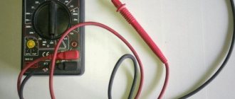
After you have decided on the quality of high-voltage wires, you can master checking high-voltage ignition wires with a multimeter.
Should high-voltage wires be replaced and when?
No matter how well the armored wires are made, they also have a limited service life. According to current regulations, they must be replaced after every 30,000 km traveled. In practice, many motorists ignore this rule, continuing to travel with wires that have already outlived their useful life.
Such inattention can cause a whole host of problems, including:
- poor ignition;
- overclocking problems;
- engine tripping;
- inability to start the car.
All these troubles are caused by one single factor - an increase in the electrical resistance of the core of high-voltage wires, as a result of which it becomes “more difficult” for the impulse from the coil to reach its destination.
You can check whether you can still drive with the old wires or not - at home.
To do this you need:
- Turn off the ignition.
- Remove one of the armored wires.
- Measure its resistance using a megohmmeter or multimeter in the appropriate mode.
- If the resistance turns out to be equal to or close to the figure indicated on the wire insulation, then it is in good condition, but if it turns out to be greater, then the wire should be replaced.
- Repeat this operation on the remaining three wires.
It should be remembered that if only one of the wires is faulty, then all four should still be replaced.
Also, do not forget about the cleanliness of the contacts of high-voltage wires - they can also cause ignition problems. If oxides are noticeable on the metal tip, they should be cleaned with fine sandpaper or a cloth moistened with kerosene. By following these simple rules for caring for armored wires and replacing them, you can almost completely avoid troubles associated with the ignition system.
How to check high voltage ignition wires?
Automotive high-voltage (HV) wires play an important role for internal combustion engines, since they help transmit high current from the ignition coil to the spark plugs. The serviceability and efficiency of the wires determines the timeliness and intensity of ignition of the fuel-air mixture, and therefore the correct and uninterrupted operation of the engine. Despite their simplicity, wires have many different “sores” and can cause a lot of troubles to their owner, which in one way or another will affect his nerves and pocket.
Malfunctions of high-voltage wires (common problems):
As a rule, the malfunction boils down to the fact that current either does not flow to the spark plug at all, or it does, but in limited quantities. This can happen for the following reasons:
- There has been a break in the conductor through which the impulse travels.
- There is a current leak, that is, the insulation is damaged and the current flows to the side.
- The resistance exceeds the permissible value.
- Problems in contacts (with a spark plug or ignition coil).
In the event of a break in the current-carrying wire, the effect of an internal spark occurs, in other words, an electrical discharge is formed between the ends of the broken wire, which reduces the voltage and causes an electromagnetic parasitic pulse. This impulse, in turn, negatively affects the correct operation of many of the vehicle's sensors. One such damaged high-voltage wire can cause vibration and interruptions in engine operation. Due to a damaged high-voltage wire, ignition in the cylinder occurs late or every other time, as a result, the synchronous operation of the cylinders and the engine as a whole is disrupted.
How to check high-voltage wires? Effective ways:
- First of all, it is necessary to check the explosive for the absence of visible damage (cracks, fractures, etc.).
- Make sure there is no breakdown, this can be determined even without instruments, just look under the hood in the dark; in the event of a breakdown while the engine is running, a spark will be visible on the explosive wire.
- You can check high-voltage wires using a wire. To do this, you need to take a piece of wire in the dark and strip it on both sides. Then one end must be shorted to ground (machine body), and the other end must be drawn along the entire length of the explosive wires , as well as joints, caps, etc. A spark will form at the breakdown sites.
- You can also check the resistance of the high voltage wires, for this you will need a multimeter.
- Turn on ohmmeter mode.
- Remove the wire from the spark plug of the first cylinder and the ignition coil.
- Connect the multimeter electrodes to the ends of the wire and look at the readings.
In good wires, the resistance should vary from 3.5 to 10 kOhm, depending on the type of wires themselves. Information about resistance is most often indicated on the insulation of high-voltage wires. Check each wire, the spread between them should not exceed 2-4 kOhm. If there is a large variation, replace the wires. By the way, they are changed as a set, that is, all together.
In conclusion, your resistance reading of the most popular high-voltage wires:
- Tesla - 6 kOhm
- Slon - from 4 kOhm to 7 kOhm (4 kOhm - 1st cylinder and up to 7 kOhm - on the last cylinder)
- ProSport - almost zero resistance
- Cargen - 0.9 kOhm
Note! The resistance of high-voltage wires varies depending on the length, thickness, and material from which the wires are made.
Wiring and free connectors VAZ 2110, 2111, 2112
I wondered what the free connectors under the panel were for, I looked at a friend’s and they were hanging the same way. First of all, I looked for them in the diagram, found No. 3 (the block connected to the air conditioner wiring harness), No. 5 (for the clock), No. 6 (for the front brake pad wear sensors).
0:465
Wire colors: Connector 1 – Yellow with blue stripe, green
0:579
1:1084
Connector 2 – Yellow Connector 3 – Pink with blue stripe, green Connector 4 – Yellow with white stripe, green
1:1281
2:1786
Connector 5 – Black, White, Orange with Black Stripe, Red with White Stripe
2:1929
3:2434
I found it in the diagram, it’s for connecting the clock)
3:86
Connector 6 – Pink with black stripe
3:154
4:659
there are two of them on the right and on the left, I also found this in the diagram for the front brake pad wear sensors
4:831
5:1336
Diagram of the injection ten
5:1388
Also on the diagram I found: A (designation 28 on the carburetor diagram) blocks for connecting the rear window washer motor (pink-black, black) C (designation 35 on the carburetor diagram) blocks for connecting the warning light harness (orange; brown-blue, black- green) Not marked on the injection diagram (designation 44 on the carburetor diagram) block for switching wires when installing headlights of a different type (green, red-gray) E (designation 47 on the carburetor diagram) block for connecting the headlight cleaner wiring harness (yellow- blue, orange-white)
5:2470
6:504
Engine control circuit 2111 (cont. M1.5.4)
6:586
And also on the engine control diagram 2111 (cont. M1.5.4) A - block connected to the wiring harness of the anti-lock brake system (ABS) B - block connected to the air conditioner wiring harness C - to the mounting block D - to the battery “+” terminal batteries E - wires connected to the ignition switch (backlight lamp) F - block connected to the blue-white wires disconnected from the ignition switch (when installing an immobilizer) G1, G2 - grounding points
6:1465
Of all these pads I found in my car, for connecting the warning light harness (connected to the instrument cluster) and the pads for connecting the rear window washer motor (under my hood next to the VUT. I’m especially interested in what kind of warning light this is. On Autolad found a topic about this, about five people were interested, no one knew.
6:2143
But I figured out a lot of things. For example, in the location of the relyushek. The rear fog light relay, central locking relay, as well as the immobilizer unit are located behind the panel, as well as the cooling fan relay, fuel pump and ignition relay. All other relays are located in the mounting block: low beam, high beam, PTF, wipers, heated rear window, etc.
6:601
7:1106
https://www.drive2.ru/l/288230376153174239/
7:1153 next article:
Selection and characteristics of on-board computers for VAC 2110, 2111, 2112
I wish there was an on-board computer - a necessary thing! And then there was the special need to change the watch,
8:2013
Rating 4.13 [4 vote(s)]
14450