Design and types of window lifters
So, what is the SP device on Kalina:
- grooves designed to fix the glass itself;
- rails that allow it to move up and down;
- sealing elements, damper, and motion limiters;
- drive mechanism;
- a lifting device that ensures the transmission of vibrations of the movement of the drive element to the glass.
Connection diagram for SP on Kalina
Depending on the drive, SPs are divided into mechanical or “meat grinders”, in which the glass is lifted by turning the handle, and also electric. In the latter, the system is controlled using a button. This electrical circuit is based on a motor with a gearbox.
In addition, joint ventures are divided among themselves and according to the type of device used that sets the glass in motion. They can be rack and pinion, cable or lever. Each of these types has its own advantages and disadvantages.
Common faults
There are many reasons why the window regulator on Kalina does not work and why the device needs to be replaced, but we will look at the main ones:
- The electric motor brushes are stuck, usually as a result of overheating of the brush elements themselves, which, as a rule, are not resistant to sudden temperature changes. Accordingly, as a result of heating the brushes, the plastic socket may melt. This will also cause the brushes themselves to lose mobility. If the malfunction has just begun to appear, you can knock on the plastic door lining several times to restore the unit’s functionality. However, over time, this method will no longer be able to produce the required result, so intervention in the design of the joint venture will be inevitable.
- The cause of the malfunction, which may require replacement of the joint venture, can also be the ill-conceived electrical circuit installed at production. The contacts themselves are not able to withstand the necessary load that is placed on them. The SP system may fail due to the fact that the electrical circuit is not supplemented with a unloading relay. So in the event of a breakdown, it often happens that the car owner has to repair not only the power windows, but also the control panel itself.
As practice shows, in most cases, repairing a unit is either completely impossible, or can be done, but with great difficulty. Accordingly, the best option would be to install a new joint venture (video author - Emilien Ok).
Vehicle Maintenance
It is recommended to replace any parts in the car only with original ones. Compliance with this requirement will eliminate subsequent unscheduled repairs. If Kalina's power window button requires servicing, then first you will need to find the necessary tools.
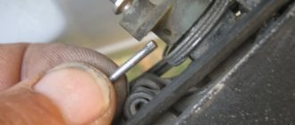
Using 2 small flathead screwdrivers, you need to remove the block from the grooves. Direct replacement is carried out without sudden movements, so as not to break fragile elements. As soon as it becomes possible to get to the wiring, you need to get rid of the plug with equal care. This can be done with little physical effort. A latch is used to disconnect the second plug.
After the glass power supply is removed, it must be inspected. The presence of any mechanical damage indicates the need for mandatory replacement. Even in-depth repairs will not help restore its functionality. Before installing a new unit, another check must be carried out. Its relevance increases when it comes to replacing a relay.
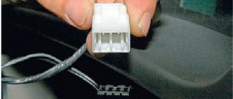
After removing the faulty part, you should manually check all connecting fasteners and wires. Traces of charring or damage are a sign that the Kalina power window button most likely needs to be replaced. If this is not done, then the need for repeated repairs will arise within 2-3 months. This is due to the increased load on the Lada window regulator.
Installation of a working unit occurs strictly in the reverse order. First, carefully connect the wires and 2 plugs. If the window lift button has been manipulated in any way, the reliability of its fixation must be checked manually. If a visual inspection does not reveal any problems, then the Kalina window lifter button is placed in its place.
Once all the wires are connected, the unit is secured using the provided latches. The repair is completed by checking the efficiency of the system.
You need to pay attention to the smoothness of the ride and the absence of the slightest delays. In the future, if the window regulator on Kalina does not work, you can fix the problem yourself
tweet
back Brake pads Lada Kalina
Forward Windshield wiper trapezoid Lada Kalina
Tags control unit, repair, window lifter, maintenance
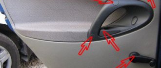
Removal instructions
The device will be dismantled starting from the front windows. Before making repairs, you need to remove the defective unit, but first you need to dismantle the door trim.
Detailed instructions for dismantling the joint venture:
- First of all, you need to lift the glass all the way and fix it at the highest point with tape. It will be a right or left window regulator, it doesn’t matter.
- After this, using a 10mm wrench, you need to unscrew the two bolts that secure the glass itself. In addition, you will need to unscrew the screw on the inner handle of the lock.
- Then you need to disconnect the system motor and wiring from the power circuit.
- Unscrew the nuts on the mechanism, there are eleven in total, and dismantle the joint venture.
- Now let's move on to the rear joints. In this case, the dismantling procedure is almost identical - first, the glass must be lifted up all the way and fixed.
- Using a size 8 wrench, you need to unscrew the three nuts securing the assembly. Then, using a 10mm wrench, unscrew two screws and three more nuts. After completing these steps, you can dismantle the unit through the corresponding hole in the bottom of the door. Having removed the joint venture, you need to assess its condition. If the problem can be solved without replacing the mechanism, then repair the device; if the malfunction is “lethal”, for example, the window lift motor or gear has failed, then installation of a new mechanism will be required.
Granta and Starline - all options
I do it whenever I have free time. Therefore, I can’t install everything at once. Yesterday I connected the electric drive in the driver's door lock. I don’t remember where I got the connector from, from which we will need female terminals. The connector was purchased at auto parts for VAZ. The price is 97 rubles, some kind of cooperative.
We pull the wiring through the post-door connector. If there are no terminals for the block, then you will have to make a hole and pull the wires through it.
Price: 97 ₽ Mileage: 11,700 km
Installation Features
As for installation, it is carried out in the reverse order of removal:
- First, the new mechanism is secured with eleven nuts.
- Then the wiring and electric motor are connected.
- After this, find the screw that secures the inner handle of the lock and tighten it completely.
- At the final stage of installation of the front joint ventures, the adhesive tape is removed.
- Next, through the hole in the rear door, a new window regulator is installed instead of the old one.
- Using a 10 mm wrench, you need to tighten all the corresponding screws and nuts. Use an 8mm wrench to tighten the nuts that secure the assembly. The tape is removed.
After completing the installation, you need to check how correctly the window opens and closes, whether there are any distortions and whether the mechanism as a whole is securely fixed. If mistakes are made, the problem must be corrected immediately so that it does not catch you at the most inopportune moment.
Sorry, there are no surveys available at this time.
You watched
A new photo report on the installation of FORWARD electric windows in the rear doors of the Lada Priora was prepared by our buyer - Alexander Vyacheslavovich Aleksashin from Moscow, as part of participation in our promotion. I finally got to the back doors of my swallow to replace the old window regulators with new FORWARD brands, which I purchased from the Steklopodem online store. RF.
Since I was already experienced in installation matters, I stocked up on clips for the inner plastic of the door, gauze tape and a set of keys.
Let's disassemble the door. Unlike the front door, the rear door is even easier to disassemble: - unscrew one self-tapping screw in the area of the door opening handle; - unscrew the two hexagons in the area of the window lift button; - unscrew the lock locking latch; - and that’s all.
Next, unclip the power window button, disconnect the plug and remove the plastic door trim.
We fix the glass with gauze tape and disconnect the power terminal of the window lift motor.
We move on to the window lift mechanism itself, which is secured with 4 bolts, unscrew them and unscrew the 2 bolts that connect the glass frame and the window lift carriage.
Next, with a little difficulty, we remove the window lift mechanism; here it is a little more difficult to get it out of the door than from the front.
We install the FORWARD rack and pinion lift, which fits very easily and simply through the door, just like through the front ones.
We connect the motor power plug and check its operation.
We install the window lifter mechanism in the standard holes. You can say they get up on their own.
We secure the mechanism with 2 bolts securing the glass and tighten the remaining 2 nuts of the mechanism itself.
Once again we check the operation of the window regulator, while securing the glass to the rack and pinion mechanism.
We put the door trim plastic back in place, replacing the damaged clips, and with “light, smooth movements” we secure it by screwing back the self-tapping screw and two hexagons.
Everyone's collected! Everything works great, better than the standard mechanism 500 times!
I am delighted with the FORWARD window lifters. The whole process of work took about 40 minutes for two doors.
Once again we thank Alexander for preparing the photo report and, as part of our promotion, we are transferring the promised prize to his mobile phone account.
You can buy FORWARD electric windows for LADA Priora (rear doors) in our online store
Schematic electrical diagrams, connecting devices and pinouts of connectors
Electric windows (ESP) are convenient devices for controlling the side windows of a car, which are controlled by a special button and make it possible to lower or raise the side windows without rotating the previously used handles. This option is provided only in some modifications of the VAZ car, but nothing prevents you from purchasing a ready-made unit and installing it yourself.
The most preferred are rack-type ESPs, so as an example we will describe the process of their installation.
The connection diagram for the window regulator on a VAZ-2110 car is as follows:
- remove the negative terminal from the car battery to stop the supply of voltage to the on-board power supply network;
- we take the wires that come standard with rack-and-pinion window lifts and make a kind of harness out of them that makes connection easy;
- remove the car mounting block, which will require unscrewing the self-tapping screw that secures the special latch;
- turn the block over and carefully install block Ш1 of the pre-prepared wiring harness into the corresponding connector;
- dismantle the door trim;
- we pull the wires to the electric window drive. To do this, you will need to carefully pass them through the holes in the door itself and the body pillar on the desired side.
General diagram of electrical equipment of VAZ 1118
1 — block headlight; 2 — windshield wiper gear motor; 3 - generator; 4 - battery; 5 - starter; 6 — sound signal; 7 — hood open sensor; 8 — power window switch for the right front door; 9 — motor-reducer for window lifter of the right front door; 10 — electric pump for windshield washer; 11 — connecting blocks of wires for connecting the right (front) speaker of the audio system; 12 — electric drive for locking the lock of the right front door with an open door sensor; 13 — ambient air temperature sensor; 14 — connecting block of the wiring harness for connection to the engine control system harness; 15 — electric drive for locking the left front door lock (with an open door sensor and a central locking switch); 16 — sensor of insufficient brake fluid level; 17 — connecting blocks of wires for connecting the left (front) speaker of the audio system; 18 — right front door power window switch (installed on the driver’s door); 19 — left front door power window switch; 20 — central locking switch; 21 — motor-reducer for window lifter of the right front door; 22 — remote control unit; 23 — immobilizer control unit (APS-6); 24 — mounting block; 25 — instrument panel; 26 — right side turn signal; 27 — glove box lighting lamp; 28 — switch for the glove compartment lighting lamp; 29 — brake signal switch; 30 — ignition switch (lock); 31 — lighting control unit; 32 — steering column switches; 33 — left side direction indicator; 34 — connecting blocks of wires for connecting the left (rear) speaker of the audio system; 35 — electric drive for locking the left (rear) door with an open door sensor; 36 — electric heater fan; 37 — additional heater resistor; 38 — heater switch; 39 — alarm switch; 40 — reverse lock solenoid switch; 41 — rear window heating switch; 42 — connecting blocks of wires for connecting the right (rear) speaker of the audio system; 43 — electric drive for locking the right rear door lock (with a door open sensor); 44 — fuel module of the engine control system; 45 — reverse light switch; 46 — parking brake warning lamp switch; 47 — cigarette lighter; 48 — reverse lock solenoid; 49 — connecting blocks of wires for connecting the head unit of the audio system; 50 — backlight lamps on the trim of the center console of the instrument panel; 51 — electric power steering control unit; 52 — interior lamp; 53 — rear light; 54 — block for connecting the electric drive for locking the trunk lid lock*; 55 — luggage compartment lid open sensor; 56 — license plate lights; 57 — additional brake light; 58 — rear window heating element; 59 — luggage compartment lighting lamp.
Alexmtx › Blog › Correct connection diagrams for electric windows (ESP) and glass closers
When you need to install ESP (electric windows) yourself, then, as always, on the Internet it is difficult to find correct and understandable diagrams for everyone. Having experience in radio electronics, I am laying out for everyone the correct and understandable diagrams for connecting an ESP, an intelligent glass closer Pandora DWM-210 (but it is better to install a Sheriff PWM-200), as well as simple closers only for raising the glass, installed in the wire gap on the positive side of the motor.
We take ESP power keys (not trigger (multiplex) from Itelm): a block from Granta, and a new model button from Kalina (it is the power key), since they are the cutest in appearance.
These are, of course, not dual-mode imported buttons, but they will work just as well with an intelligent door closer. We also install the Sheriff PWM-200 type door closer itself. We use thick power wires (shown in bold in the diagrams) >= 1 mm2, while control wires can be used thin = 0.5 mm2.
Power buttons are easy to identify by their contacts - they have thick and flat blades, while trigger buttons have thin pins like needles! Exception! If the buttons are not on the door, but on the center console and thick wires >= 1.5 mm2 are stretched from them to each door, then you can do without a relay, since there is no duplicate button here, and each one has its own door and the drawdowns are minimal. Then you don't have to read further.
Plus +12V must be taken from the fuse block, and not from the ignition, otherwise the automatic window closer will not work when arming. It is better to take the weight from the bolt behind the mounting block, and not in the door, since the contact in the door may not be very good. Although the door contact is also good if the car is not old. Take tinned terminals.
Connection diagram for power window lifter button "AVAR"
Diagrams for connecting the backup button on the driver's door to the main button on the passenger door
When installing two buttons on one window regulator, they are usually installed in series (or in parallel, but then they must be decoupled via a relay).
The main button is the button that controls the power window of the door on which it is installed. The duplicate button is the driver's button, which additionally controls another window regulator from the driver's seat.
Daisy chain connection (for trigger buttons)
We connect the output of additional button 1 in the driver's door to input 6, and output 7 to input 3 of the main button on the passenger door. We cut the wires in the block connecting contacts 5-6 and 6-3. The minus of contact 5 now goes only to the backlight, and contacts 6 and 3 now take output from additional buttons 1 and 7 of the driver's door. Installation in parallel will result in short-circuiting during lifting and lowering. Power wires are highlighted in bold.
Parallel connection (only for power buttons)
Since with a serial connection you still can’t do without a relay, it is better to make a button duplication circuit in parallel, decoupling the main button from the backup button through two 5-pin relays: the wires from the main button next to the driver’s ESP motor go directly to the 88th contact of the relay and from pin 30 directly to the engine, and long wires from the backup button go to pin 85 of the relay winding, and the relay feeds a powerful plus to the passenger’s ESP engine.
A parallel connection for power buttons is preferable, since there is no need for a relay on the main (passenger) button (the wires here are short), and we thereby eliminate unnecessary clicking of the relay when the main button on the passenger door operates. For non-power (trigger) buttons, in this case, you will definitely have to use 2 more extra relays to relieve the load on the passenger button (therefore, a serial connection is always used for trigger buttons). Further, everywhere in my circuits a parallel connection is used, since all the buttons are power
.
Connection diagram for multiplex (low-current) ESP button
ESP connection diagram when the multiplex button closes the contacts to ground
Dimensions of the installation location for the ESP “AVAR” buttons
Glass closer Pandora DWM-210
What it gives: - full glass travel in one short press (“one touch”) - BUT DOES NOT WORK ON 2 GLASSES AT THE SAME TIME (since the module has only one sensor for electromagnetic noise of the motor, current and time); — stopping the glass in any position by pressing again in any direction; — automatic stop of the glass when it encounters an obstacle in the window opening; — automatic shutdown of ESP motors when current is exceeded; — automatic closing of windows when arming the car; — automatic opening of the windows when disarming to the previous position before arming, if the parking lasted no more than 20 minutes. (The rev counter works rather conditionally and may leave the windows closed or not closed enough). The closer is installed in the driver's door.
ATTENTION! When you hold the button, the closer does not use its relays
, which take the plus (through a 20A fuse) and minus from the closer, but sends all the current directly from the button to the motor, so you need to install a relay after leaving the button with long wires!
Apparently this was done so that if the door closer fails, you can always close the window by simply holding the button. When you briefly press
the button, the door closer with its relays is activated and closes the glass.
Place the relay only at the input to the closer from the output after the duplicate button!
If this is not done, then due to subsidence along the long wires of the sequential connection of the buttons, the passenger window will barely move.
The output of the closer must be connected directly to the motor without a relay, otherwise the detection of electromagnetic noise from the motor will not work and the closer will not work!
At the output of the driver's power button, relays are not needed, since all the power wires there are short.
It is ideal to install 2 door closers on each door, as is standard on foreign cars - then the AUTO mode will be on 2 doors at once in parallel, and not alternately. In addition, you will not need to pull 2 extra thick wires to the motor from the driver's door to the passenger's door. If I had known right away that the Pandora DWM-210 is such a Ketai crap without its own relays in the power part of the closer, I would have purchased and installed a Sheriff PWM-200
, in which the power part is clearly separated from the control part and, moreover, you can close two windows at the same time in one touch! So it's definitely better!
This is interesting: How to bleed shock absorbers before installation
The power windows are turned on by the module sequentially after a trigger pulse is given: first the driver's door, then the passenger door, and the next channel is turned on after the previous one has been completed. If the glass is already closed, the module will immediately switch to the next channel. Closing control is carried out by electromagnetic noise from the motor.
When the power is turned on, the closer module needs to be calibrated based on the protection current. You need to press SHORTLY to lower each glass all the way, then raise it in the same way. At the same time, the closer remembers the characteristics of the engine. The control signal for closing and opening is NEGATIVE ONLY. Control can be done from the central locking or from an additional alarm channel. It is necessary to connect the control output of the security system to the “White/Red” (windows up) and “White” (windows down) terminals of the module, respectively. The duration of the trigger pulse must be at least 500ms. (0.5 sec.). Attention: in older releases the wires of the buttons and motors were swapped - for such blocks we swap the wires under the numbers: 9 2, 16 20, 15 10, 14 19, 13 18. On the latest Pandora (November 2011 and newer) the diagram is correct, so that there is no need to swap wires from buttons and motors!
Closer in wire break for lifting ESP
Addition dated 10/05/2014 at the request of SIBUR95. There are closers that are connected to the break in the lifting wire that goes to the ESP motor. There are 2 wires coming from the closer and they are constantly closed in it. When you turn on the closer, they break and + appears on one, and nothing on the second. On GREEN, when the door closer is operating (arming), a plus appears and it goes to the engine, and a minus goes from the button (or from the relay from contact 88 to 30) to the engine. When the closer does not work, it simply passes current from BLUE to GREEN by closing its relay and that’s it.
Here the circuit differs only in that the minus of the motor is connected directly to the button (or to the relay, if the button is duplicated), and the plus also passes through the closer, and the relay is located at only one input to the closer, thereby not interfering with the detection of engine noise.
You can also make a button duplication circuit not in series, but in parallel on two 5-pin relays. The advantage is that a series circuit is eliminated; the relay will not click again from the main button, which is closer to the engine (with short wires), but only from the backup one. The downside is that for non-power (trigger) buttons in this case you will have to use 2 extra relays (relays 3 and 4 in the diagram).
Scheme for any number of duplicate buttons and number of doors
You can put as many buttons in parallel as you like and simultaneously press them in different directions - a short circuit is impossible from the circuit design! In a situation where we press the up button on the main button, and the down button on the backup button, it will simply stop, since both power lines will have the same potential.
The only difference between the closer is the presence of an MK between the buttons and power relays. The advantage of the circuit is that the power switching is in one place, there are no losses in the harnesses and on the buttons, there is a minimum of “pulling” of wires - 2 in total per channel + ground. In good quality, full-featured closers, the power part and control lines are implemented in the same way + the functions of “auto-detection” of active control levels are also added.
If a door closer of the PWM-200 on Sheriff type with low-current control is installed, then there is no point in these relays, since they are already mounted in the door closer. This circuit with a relay is for understanding the essence of reverse control and duplicating buttons in parallel. Power outputs both in the central locking system and in the door closers are implemented in exactly this way.
It is also advisable to connect non-polar electrolytic capacitors of 22 uF 25V to the contacts of the ESP motors in order to smooth out the range of current ripples in the power channel of the closer so that it works correctly even when the motors are worn out and does not suddenly stop the glass when opening and closing.
The usual scheme of duplicate buttons for 4 doors
Duplicate buttons must also be supplemented with two 5-pin relays (they are not shown in the diagram).
Lada Kalina dashboard diagram
1,2,3,4 — blocks of the instrument panel wiring harness to the blocks of the rear wiring harness; 5,6 — blocks of the instrument panel wiring harness to the blocks of the front wiring harness; 7 — block of the instrument panel wiring harness to the block of the wiring harness 8 — block of the instrument panel wiring harness to the block of the front wiring harness; 9 — lighting control module; 10 — ignition switch; 11 — on-board computer mode switch; 12 — windshield wiper switch; 13 — sound signal switch; 14 — light signaling switch; 15 — instrument cluster; 16 — evaporator temperature sensor; 17 — interior air temperature sensor; 18 — air conditioner switch; 19 — controller of the automatic climate control system; 20 — heater damper gearmotor; 21 — rear window heating switch; 22 — alarm switch; 23 — brake signal switch; 24 — cigarette lighter; 25 — electric amplifier control unit; 26,27 — blocks of the instrument panel wiring harness to the radio; 28 — backlight lamp for the heater control panel; 29 — illuminator; 30 — mounting block: 31 — heater electric motor switch; 32 — heater electric motor; 33 — additional resistance of the heater electric motor; 34 — glove box lighting; 35 — glove box lighting switch; 36 — control unit of the APS-6 automobile anti-theft system; 37 — driver airbag module; 38 — passenger airbag module; 39.40 — blocks of the instrument panel wiring harness to the blocks of the ignition system wiring harness.
KZ - additional starter relay; K4 - additional relay; K5 - relay-interrupter for direction indicators and hazard warning lights; K6 - windshield wiper relay; K7 - headlight high beam relay; K8 - sound signal relay; K9 - relay for turning on fog lights; K10 — relay for turning on the heated rear window; K11 — electric seat heating relay; K12 - air conditioning compressor clutch activation relay;
Instrument panel wiring harness - 11186-3724030-20.
Ignition system diagram Lada Kalina Lux
1 — oil pressure warning lamp sensor; 2 — coolant temperature indicator sensor; 3 — additional fuse block; 4 — fuses for the electric fan of the engine cooling system; 5 — electric fuel pump relay; 6 — relay for the electric fan of the engine cooling system; 7 - ignition relay; 8 — relay 2 of the electric fan of the engine cooling system; 9 — relay 3 of the electric fan of the engine cooling system; 10 — electric fan of the engine cooling system; 11 — throttle position sensor; 12 — idle speed regulator; 13 — coolant temperature sensor; 14 — diagnostic block; 15 — ignition system harness block to the instrument panel harness block; 16 — solenoid valve for purge of the adsorber; 17 — speed sensor; 18 — ignition system harness block to instrument panel harness block 2; 19 — mass air flow sensor; 20 — crankshaft position sensor; 21 — oxygen sensor; 22 - controller; 23 — rough road sensor; 24 — diagnostic oxygen sensor; 25 — ignition coil harness block to the ignition system harness block; 26 — ignition coils: 27 — ignition system harness block to the ignition coil harness block; 28 — spark plugs; 29 — nozzles; 30 - resistor; 31 — air conditioning system pressure sensor; 32 — blocks of the ignition system harness and injector wiring harness; 33 - phase sensor; 34 - knock sensor.
Ignition system wiring harness -11184-3724026-10. Ignition coil wiring harness -1118-3724148-00. Injector wiring harness -11184-3724036. A - to the “plus” terminal of the battery.
Some owners of the 2nd generation Lada Kalina encounter problems with the operation of the front or rear power windows (ESP) already during the break-in period of the car. There may be several reasons for this malfunction; all of them are described in this article.
Wiring diagram of power windows Lada Kalina 2
Left door wiring harness diagram : 1 - block to the rear wiring harness; 2 — electric window lifter motor; 3 — door lock; 4 — switch block; 5 - to the speaker; 6 - mirror.
Wiring harness diagram for the right front door : 1 - block to the rear wiring harness; 2 — electric window lifter motor; 3 — door lock; 4 — window lift button; 5 - to the speaker; 6 - mirror.
Rear door wiring harness diagram : 1 - block to the rear wiring harness; 2 - speaker; 3 — door lock; 4 — window lift button; 5 - electric window lift motor.
How to determine why the window regulator does not work
1. In the mounting block, check the power window fuse (F2, 25A) and relay (K2).
2. Remove the door trim and check the voltage at the power window motor terminals using a multimeter or a 12V test lamp.
If there is no voltage, then check the serviceability:
- power window buttons
- wiring (connector connection)
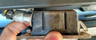
- electrical package control unit (central body electronics unit or CBKE), which is used in the “luxury” configuration.
If current flows to the electric motor, but the glass does not move, then we check:
- malfunction of the window lift motor (for example, the drive motor brushes are stuck/sticking, the plastic gear in the gearbox is worn out)
- The window lift cable is frayed
- glass is jammed (distorted)
The most common problems with power windows are:
- Window lift motor malfunction.
- Skewed, broken power window cable.
- Poor contact.
Let us remind you that on the website you can find solutions to other problems in the operation of the Lada Kalina 2, for example, squeaking clutch pedals.
How to fix stuck power window buttons on a Priora
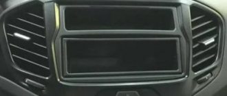
If the power window buttons work every once in a while or get stuck, but at the moment it is not possible to purchase a new control unit, you can fix the problem as follows:
- We remove the control unit. To do this, you need to carefully snap off the 6 plastic clips on the body of the decorative cover;
- Let's disassemble the block. To do this, you also need to unclip 6 clips on the body of the unit itself;
- We take out the control board and clean it of any contaminants;
- We remove the buttons themselves by carefully bending the side fastenings with a screwdriver;
- We remove all dirt and debris from the paths using alcohol and cotton wool;
- Lubricate the working part of the button with silicone grease (this is not necessary, but this will make the button move smoother);
- We assemble everything in reverse order.
Replacing the power window button Renault Logan and Megan
VIDEO REVIEW » alt=»»>
You can also replace the power window button block on Renault Logan and Megan cars yourself.
- All you need is a flathead screwdriver and a cloth or tissue.
- To remove the control unit, just carefully pick it up with a screwdriver and gradually pull it out of its seat. To avoid accidentally damaging the casing during dismantling, it is recommended to wrap the screwdriver in a thin cloth.
- Next, you need to disconnect the terminals with the wires, making sure that they do not fall inside the casing. Then you need to connect the new unit and install the buttons in place.
Sometimes, during the run-in phase of the car, the power window control unit begins to malfunction; Kalina is no exception in this case. Often such a block simply refuses to move the rear or front windows in space.
There are many reasons for this. The most common are assembly defects and operating errors. In any of these cases, you can independently diagnose Kalina's power windows.