Checking the serviceability of the VAZ 2107 generator and its connection
A car generator is designed to provide electricity to car systems. Of course, provided that the engine is running. There is also a car battery “on board”, but its supply of electricity will not last long. Energy consumption increases at night when the headlights are on and the audio system is on.
If the generator fails, normal operation of the machine becomes impossible. In this case, it is necessary to diagnose it in order to understand exactly what is broken.
Checking an Individual Regulator
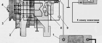
Checking the voltage regulator of the G-222 generator: 1 - battery; 2 - voltage regulator; 3 - control lamp.
As a rule, separate voltage regulators were installed on old cars, including domestic VAZs. But some manufacturers continue to do this to this day. The verification process is similar. To do this, you need to have a power supply with a voltage regulator, a 12 V light bulb, a multimeter and a directly tested regulator.
To check, you need to assemble the circuit shown in the figure. The process itself is similar to the one above. In normal condition (at a voltage of 12 V), the light bulb lights up. When the voltage value increases to 14.5 V, it goes out, and when it decreases, it lights up again. If during the process the lamp lights up or goes out at other values, it means that the regulator has failed.
Checking relay type 591.3702-01
Relay test diagram type 591.3702-01
You can also still find a voltage regulator of type 591.3702-01, which was installed on rear-wheel drive VAZs (from VAZ 2101 to VAZ 2107), GAZ and Moskvich. The device is mounted separately and installed on the body. In general, the test is similar to that described above, but the differences are in the contacts used.
In particular, it has two main contacts - “67” and “15”. The first of them is a minus, and the second is a plus. Accordingly, to check it is necessary to assemble the circuit shown in the figure. The verification principle remains the same. In normal condition, at a voltage of 12 V, the light bulb lights up, and when the corresponding value increases to 14.5 V, it goes out. When the value returns to its original value, the light comes on again.
A classic regulator of this type is a device of the PP-380 brand, installed on VAZ 2101 and VAZ 2102 cars. We provide reference data regarding this regulator.
| Adjustable voltage at regulator and ambient temperature (50±3)° C, V: | |
| at the first stage | no more than 0.7 |
| on the second stage | 14,2 ± 0,3 |
| Resistance between plug “15” and ground, Ohm | 17,7 ± 2 |
| Resistance between plug “15” and plug “67” with open contacts, Ohm | 5,65 ± 0,3 |
| Air gap between armature and core, mm | 1,4 ± 0,07 |
| Distance between second stage contacts, mm | 0,45 ± 0,1 |
Testing a three-level relay
Regulated power supply
Some car owners install on their cars, instead of standard “chocolate bars,” three-level relays, which are technologically more advanced. Their difference is the presence of three voltage levels at which the battery power is cut off (for example, 13.7 V, 14.2 V and 14.7 V). The appropriate level can be set manually using a special regulator.
Such relays are more reliable and allow flexible adjustment of the cutoff voltage level. As for checking such a regulator, it is completely similar to the procedures described above. Just do not forget about the value that is set on the relay, and accordingly, check it with a multimeter.
Generator check
There is one method by which you can check the performance of a car generator equipped with a regulator relay 591.3702-01 with diagnostic elements. It is as follows:
- disconnect the wires that went to pins 67 and 15 of the voltage regulator;
- connect a light bulb to it (excluding the regulator from the circuit);
- Remove the wire from the positive terminal of the battery.
If, as a result of these actions, the engine does not stall, then we can say that the car’s generator is in order. Otherwise, it is faulty and needs to be checked and replaced.
How to check the serviceability of the VAZ 2107 generator?
First, let's find out what the generator consists of, in principle. With some exceptions, all car generators have a similar list of components:
- Rotor . This is the part of the generator that rotates.
- Stator . It is also the housing on which the capacitor and contact terminals are mounted. Bearings for the rotor are also firmly mounted in the housing.
- Front and back covers . Removable, provide access to the “insides” of the generator.
- Voltage regulator . It can be built-in (integrated into the design) or replaceable.
- Mounting points.
Checking the generator and its components using a multimeter
A car alternator is a fairly reliable device and can last for many years without replacement. It most often breaks down due to water getting into it, which leads to rusting and destruction of its parts. Its bearings may also wear out.
Where to start checking the generator?
To begin with, it is advisable to remove it from the machine by disconnecting the mounting bolts and removing the belt from the pulley. Next, let's examine it carefully.
Pay attention to the color of its stator winding (the stator is the outer part of the generator, which is wound with a thin copper wire). This winding should not have any traces of darkening, black spots or obvious signs of burning.
The fact is that the copper wire with which the stator is wound has varnish insulation, which begins to darken when overheated excessively, so if the generator was operating with an overload, the wire becomes dark and this is immediately noticeable
It is important to distinguish between the color of the winding that has darkened due to high temperature and that is simply dirty due to oil or dust.
Connecting the VAZ 2107 generator
The procedure for replacing a generator on a VAZ 2107 consists of its removal, installation, and connection. To dismantle the generator, follow this algorithm:
1. Be sure to turn off the power to the car by removing the negative terminal from the battery.
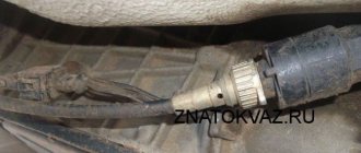
2. Next, disconnect the connector from the generator.
3. Having removed the protective cover, disconnect the terminal with a “10” key, and then remove the wire.
4. After loosening the generator, remove the drive belt.
5. Using a 17mm wrench, unscrew the nuts and remove the adjusting bar.
6. After unscrewing the lower mounting nut, remove the bolt and bushing.
7. You can dismantle the generator.
Install the new generator in reverse order. Before you begin installing the generator device, we recommend that you familiarize yourself with the electrical connection diagram for the VAZ 2107 generator.
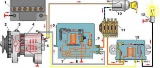
Connection diagram for the VAZ 2107 generator
Numbers from 1 to 6 indicate the main elements of the power supply system:
mounting block with relays and fuses.
measuring device for monitoring voltage.
battery charge indicator lamp.
Adjusting the tension of the generator belt
After installation, the belt tension should be adjusted. To do this, loosen the 2 bolts securing the unit. Using a pry bar, tighten the belt and secure it with a nut on the adjustment plate. Next, check the degree of tension by lightly pushing the belt in between the pulleys.
The deflection should be between 10 and 17 mm. Please note that the tension procedure must be repeated until the correct value is obtained. Having optimally tensioned the belt, finally tighten all the fastening nuts. At this point, the connection of the generator can be considered complete.
Generator VAZ 2106: purpose and functions
A car generator is a small electrical device whose main task is to convert mechanical energy into electrical current. In the design of any car, a generator is needed to charge the battery and feed all electronic devices while the engine is running.
The generator's task is to ensure uninterrupted operation of all electrical systems of the machine and the battery.
How exactly does the generator work on a VAZ 2106? All processes of energy conversion from mechanical to electrical are carried out according to a strict scheme:
- The driver turns the key in the ignition.
- Immediately, the current from the battery through the brushes and other contacts enters the excitation winding.
- It is in the winding that the magnetic field appears.
- The crankshaft begins to rotate, from which the generator rotor is also driven (the generator is connected to the crankshaft by a belt drive).
- As soon as the generator rotor reaches a certain rotation speed, the generator enters the self-excitation stage, that is, in the future, all electronic systems are powered only from it.
- The generator performance indicator on the VAZ 2106 is displayed in the form of a control lamp on the dashboard, so the driver can always see whether the device has enough charge for full operation of the car.
Standard device for the "six"
Design of the G-221 generator
Before talking about the design features of the VAZ 2106 generator, it should be clarified that it has unique clamps for mounting on the engine. On the body of the device there are special “ears” into which studs are inserted and tightened with nuts. And so that the “ears” do not wear out during operation, their internal parts are equipped with a high-strength rubber gasket.
The generator itself consists of several elements, each of which we will now consider separately. All these devices are built into a light-alloy cast housing. To prevent the device from overheating during long-term operation, the case has many small holes for ventilation.
Why the VAZ 2107 generator fails and its step-by-step check
The device is securely fixed in the engine and connects to various car systems
Winding
Due to the fact that the generator has three phases, windings are installed in it immediately. The purpose of the windings is to generate a magnetic field. Of course, only special copper wire is used for their manufacture. However, to protect against overheating, the winding wires are covered with two layers of heat-insulating material or varnish.
Thick copper wire rarely breaks or burns out, so this part of the generator is considered the most durable
Relay regulator
This is the name of the electronic circuit that controls the voltage at the output of the generator. The relay is necessary to ensure that a strictly limited amount of voltage reaches the battery and other devices. That is, the main function of the relay regulator is to control overloads and maintain an optimal voltage in the network of about 13.5 V.
A small plate with built-in circuitry to monitor the output voltage
Rotor
The rotor is the main electric magnet of the generator. It has only one winding and is located on the crankshaft. It is the rotor that begins to rotate after the crankshaft starts and gives movement to all other parts of the device.
The rotor is the main rotating element of the generator
Generator brushes
The generator brushes are located in brush holders and are needed to generate current. In the entire structure, it is the brushes that wear out the fastest, since the main work of generating energy falls on them.
The outer side of the brushes can quickly wear out, which is why there are interruptions in the operation of the VAZ 2106 generator
Connection diagram for generator 37.3701 for VAZ 2108, 2109, 21099 cars
Diode bridge
A diode bridge is most often called a rectifier. It consists of 6 diodes that are placed on a printed circuit board. The main job of a rectifier is to convert alternating current into direct current to maintain stable operation of all electronic devices in the car.
Due to its specific shape, drivers often call the diode bridge a “horseshoe”
Pulley
The pulley is the driving element of the generator. The belt is tensioned simultaneously on two pulleys: the crankshaft and the generator, so the operation of the two mechanisms is continuously interconnected.
One of the generator elements
Reasons for generator failure
Without specialized equipment, it is not always possible to determine the exact cause of a unit failure. But most often the problem is caused by:
- Bearing jamming . Due to drying out of the lubricant and gradual wear, the bearings jam. First, the belt usually breaks, which necessitates rebuilding the assembly.
- Winding burnout . Most often, the winding burns out due to the penetration of chemicals and salts used to sprinkle the road in winter.
- Brush wear . Graphite brushes wear out gradually, so they need to be replaced periodically. If they are not replaced in time, the unit may fail completely.
- Relay malfunction . The device is designed to prevent battery overcharging. If it malfunctions, the generator does not start.
In what situations is replacement necessary?
Wear of the element is characterized by such manifestations as cracks or tears in the canvas, worn teeth and uneven edges. If you ignore such a deplorable state of a very important element, it will come back to haunt you with overheating and boiling of the engine, independent operation of the battery, which will lead to its rapid discharge.
If the belt is severely worn, it also shows signs of noise to the owner - it begins to whistle, especially at low speeds. The next reason for a whistling belt may be water getting on its surface, which occurs due to worn-out pipes of the cooling system - antifreeze begins to leak.
Some belts - oak ones - whistle when the car starts in frosty weather, and after warming up the sound is lost. A weak tension is expressed by a whistle, but in this case it is quite easy to overtighten.
how to remove the generator
from a
VAZ
of the traditional model range.
More details: 2107
.html Subscribe!
Check Features
When checking the generator of a VAZ 2110, 2107 and others for serviceability, the following conditions must be met:
- An accurate multimeter should be used for diagnosis.
- The normal voltage is 12 V.
- If it is necessary to replace the wiring, you must use wires with the same cross-section as the original.
- Before checking, you should check that all fasteners are connected correctly and the belt tension is correct. If necessary, the connections should be adjusted to normal, the belt should be loosened or tightened.
During the verification process it is prohibited:
- short circuit the wires;
- connect terminals that differ in purpose and parameters, connect terminal 30 or B+ to ground;
- diagnose a generator without connected consumers.
Checking charging with the terminal removed
Removing the battery terminal while the engine is running is an old, proven method of checking the functionality of the generator; this method was used on Soviet cars. We check like this:
- start the engine;
- disconnect the negative terminal and move it to the side;
- if the engine turns off, it means there is no charging, you need to deal with the generator;
- Without installing the terminals, we add speed, the internal combustion engine should not stall.
You should also pay attention to this point - when installing the negative wire in place while the engine is running, the idle speed should not change noticeably. A significant decrease in speed indicates that the battery is quite discharged, and attention should be paid to this. A discharged or faulty battery may fail on the road; it is better not to travel with such a battery.
An important point is that you need to remove the terminal with the engine running very carefully; the wire should not touch live parts of the car (body, engine housing, etc.). On many modern cars, it is generally not recommended to disconnect the terminal while the internal combustion engine is running; if there is insufficient confidence in the test results, it is better not to use this method.
It is worth noting that there is still a way to check with a test light, but we will not consider this method - the lamp only indicates the presence or absence of charging, with its help it is impossible to determine the value of the voltage in the network and its dependence on the load.
Diagnostics of the VAZ generator without removal and special tools
This is not the most reliable and reliable method, but it allows you to determine whether the generator is functioning or there are malfunctions. The use of any specialized tools, including a multimeter, is not required. There is no need to remove the generator.
To diagnose, start the engine and turn on the low beams. In operating condition, the negative terminal must be disconnected from the engine. The uniform light of the headlights and the stability of the engine stroke indicate normal operation of the generator. If malfunctions are observed or the brightness of the light changes, the VAZ generator is probably faulty; in-depth diagnostics need to be carried out.
How to check battery charging and generator performance with a multimeter?
To understand the process, consider the generator device:
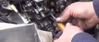
Failure of any of the components will lead to disruption of the entire unit. First, the mechanical part is checked. There is no need to remove the generator; just remove the drive belt from the pulley.
Rotate the shaft by hand and make sure that the rotor rotates freely in the bearings. When the brushes are worn critically, a characteristic grinding noise will be heard.
Then check the integrity and fastening of the power and control cables. If visual inspection does not help to find the fault, the generator will need to be checked with a multimeter.
This procedure does not require a professional device with many functions. Three modes are sufficient: “continuity test”, “resistance measurement”, “voltage measurement”.
Voltage Regulator Diagnostics
To check the voltage regulator on a VAZ 2114, 2106 car, you should perform the following steps:
- Start and warm up the engine by turning on the headlights. Warm up the engine for about 15 minutes. For diagnostics, a multimeter or voltmeter capable of taking measurements in the voltage range 0-15 V is used.
- Measure the voltage between ground and terminal 30. For most cars in normal condition, the reading will be within 13.5-14.6 V. A value less than 13 V means the unit needs to be replaced.
How to check the generator without removing it from the car
In connection with the successful elimination of the problem in the generator, I decided to summarize the experience and write separate articles on diagnostics and troubleshooting using the example of generator 9412.3701 from the VAZ-2107. If you have established for sure that it is the generator that is faulty, then we arm ourselves with a multimeter or a test light (screwdriver), connected to the battery.
First, remove the positive “ ” terminal from the battery to avoid accidental short circuit, then disconnect all contacts from the generator and, bending the latches, remove its back cover (the design of which provides for this). In this way we can carry out a general check of the diode bridge and stator winding, as well as the rotor. To check the voltage regulator, you need to remove it from the car's generator.
So, let's get started: switch the multimeter to the “diode continuity/circuit integrity check” mode.
1. First, check the generator for a short circuit to ground.
We press the positive “ ” probe of the multimeter to terminal “30” of the generator, and the negative “-” probe to its body. In good condition, the diode bridge does not pass current in this direction, there is no sound signal, and the light bulb does not light up.
| Fig. 4 “1” - Resistance tends to infinity - no current passes |
When an alarm occurs or the control lamp lights up, we have a short circuit of the diode bridge or stator winding to ground.) To exclude the stator in this case, it is necessary to remove the diode bridge from the generator.
2. Check the positive diodes for breakdown.
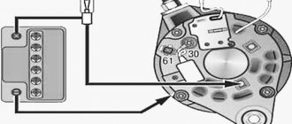
We press the positive “ ” probe of the multimeter to terminal “30” of the generator, the negative “-” to the terminals of the winding and diodes (generators type 9412.3701, where the bolts are insulated from the terminals with textolite washers and are connected to ground), or one of the bridge mounting bolts (generators type 37.3701, where the bolts are connected to the terminals, but isolated from the “ground” - Fig. 5).
If the diodes are working properly, then the resistance tends to infinity, and the light bulb does not light up. If even one of them is “broken,” the light comes on and the multimeter beeps. When changing polarity, they must pass current.
3. Check the negative diodes for breakdown.
To do this, press the positive “ ” probe of the multimeter to the terminals of the winding and diodes (generators type 9412.3701), or to the bridge mounting bolts (generators type 37.3701—Fig. 5). We press the negative “-” against the generator housing.
If the resistance tends to infinity and there is no sound signal, the lamp does not light - the negative diodes are working. When changing polarity, they must pass current.
4. We check additional diodes for breakdown.
We press the positive “ ” probe of the multimeter to the input “61” of the generator. Negative “-” probe to the terminals of the winding and diodes (generators type 9412.
3701), or to the bridge mounting bolts (generators type 37.3701—Fig. 5). If the resistance tends to infinity and there is no sound signal, the lamp does not light - the additional diodes are working.
When changing polarity, they must pass current.
To determine a break in the diode, you will also have to remove the diode bridge from the generator.
It is worth noting that testing diodes with a multimeter and, to a lesser extent, with a light bulb, in which the diodes are tested under load, are not a 100% effective method.
For this, there are more accurate instruments, such as an oscilloscope.
If the diode bridge is working properly, then we proceed to checking the stator winding.5. Check the stator winding for open circuit.
We alternately connect the multimeter probes between all three terminals of the stator winding.
| Fig. 9 “000” - current flows through the circuit |
A sound signal or a lit lamp in all three cases tells us about the integrity of the winding.
6. Check if the stator winding is shorted to ground.
We connect the probe to one of the winding terminals, and the other to the generator housing. If the resistance tends to infinity, there is no sound signal, the lamp does not light - there is no short circuit.
| Fig.10 |
7. Check the stator winding for interturn short circuit.
To do this, switch the multimeter to the “200 Ohm” resistance measurement mode and connect the probes between all three terminals of the stator winding. The resistance should be 0.2-1.2 ohms and be the same between all three terminals.
To check the rotor winding, it is necessary to remove the brush assembly with the voltage regulator.
8. Check the rotor winding for breaks.
To do this, we connect the probes to the contact rings of the rotor - the multimeter should emit a sound signal, and the indicator light should light up accordingly, which indicates the integrity of the circuit.
9. Check that the rotor is shorted to ground.
We connect one probe to the slip ring, and the second to the generator housing. If “Resistance tends to infinity”, there is no sound signal, the lamp does not light, then everything is in order.
10. Let's check the rotor winding for an interturn short circuit.
We similarly switch the device into the “200 Ohm” resistance measurement mode and connect the probes to the slip rings. The rotor winding should have a resistance of 1.5 - 5.0 Ohms, depending on the type of generator.
If one of the above problems is detected, it is necessary to remove the generator and repair it or replace the failed part. In the next article I will tell you how to correctly find a broken diode and check the relay regulator for serviceability.
There are two ways, using a multimeter and without it at all. The first, relatively new one, is to check the voltage at the battery terminals, and the second, old and proven one, is almost the opposite - the battery terminal must be removed with the engine running.
- Checking the battery with a multimeter first occurs at rest - the voltage should be in the range of 12.5-12.8 V. Then you need to measure the readings with the engine running, if 13.5-14.5 V is observed at 2 thousand revolutions, then everything is in order. Moreover, on new cars, even 14.8 V is quite normal, as manufacturers claim - the abundance of electronics affects it. In conclusion, it remains to check the voltage under load, that is, by connecting consumers - the stove, headlights, heating, radio. A dip in the range of 13.7–14.0 V is considered acceptable, but 12.8–13 V already indicates a malfunction.
- The second method, like many “old-fashioned” ones, is simple and trouble-free, but at the same time quite dangerous and requires care. It allegedly works both on VAZs and on relatively new cars, like the Aveo. What is the point - loosen the bolt securing the negative terminal of the battery with a 10mm wrench, start the engine and give a small load, turning on one of the consumers, for example, the headlights. Then remove the terminal while the engine is running - if it does not stall and the headlights do not dim, then everything is absolutely fine with the generator, otherwise you can be sure that it is broken. You should try this method at your own peril and risk.
Checking the return current
Diagnostics is carried out with the engine running at high speeds. It is necessary to measure the current consumed by the vehicle components. The probe is pressed against the wire from terminal 30 or B+.
It is necessary to turn on the electrical appliances of the car one by one and record the indicators. The resulting values should be summed. Then you need to turn on all the devices and measure the current indicator. The resulting indicator should be compared with the summed value of previous measurements. The final value should be approximately 5 A below the summed value. A higher value confirms that the node is faulty.
How to check the drive belt?
From the very beginning, the voltage is kept at an optimal value, and then a sharp drop begins. This may be caused by a sharp increase in engine speed, followed by normalization during operation at a stable speed. All this suggests that the generator drive belt is slipping in the system. The belt could stretch for various reasons, and the pulley itself could fail. In general, it is necessary to disassemble and look.
It is useless to tighten the belt again; it must be replaced with a new one. When installing a new belt, it is important to monitor its tension level, because excessive tension can lead to destruction of the generator bearings. Also note the magnitude of his plunge into the stream. If the belt fails, it is worth replacing the pulley itself.
Checking the windings
First you need to visually inspect the windings. If there are no visible defects, you should use a multimeter. First you need to do the following:
- Remove the brush holder.
- Disconnect the voltage regulator.
- Clean the slip rings.
- Diagnose the winding for defects.
The resistance measurement function on the multimeter should be activated. The measurement is taken between the slip rings and the stator. In normal mode, the value will be from 5 to 10 ohms.
Generator faults
- The generator generates current at a very low voltage.
- The generator has stopped producing electricity.
- The dashboard lamp indicates a generator breakdown.
- The generator generates current above the optimal rate.
- Extraneous noise arose when the generator was operating.
Before you begin repairing the generator, check the condition of the generator drive belt for wear and belt tension (the check is carried out by pressing on it, the belt should not bend more than 2 mm). If the belt is not very worn, the tension can be corrected by tightening it a little. Check the tension roller of the generator; it should turn easily and not make unnecessary sounds (if the roller does not scroll well and makes unnecessary sounds, it should be replaced). Then you should remove and disassemble the generator to check the technical condition of the generator.
Generator diagnostics
In the future, you will need the following measuring instruments to check the technical condition of the generator :
- ammeter;
- voltmeter;
- rheostat.
The rotation speed of the generator rotor can tell us a lot, which we can check using the tachometer on the instrument panel. Normal tachometer readings with a working generator should be in the range from 2000 to 5000 rpm.
Causes of generator malfunction and repair, possible causes of generator failure:
If during testing you find that the generator does not produce a charge, this may be due to the following reasons:
- Contacts or fuse are burnt out.
- Damage or wear of the generator brushes.
- Regulator relay malfunction.
- A break in the stator or rotor circuit due to a short circuit in the winding.
Elimination of the above listed generator malfunctions is solved by replacing worn parts.
How to remove and disassemble the generator. Do-it-yourself generator disassembly.
- Remove the brush holder with the voltage regulator, having first unscrewed all the fasteners.
- Remove the tension bolts and the cover with the stator.
- Disconnect the phase windings from the output wires of the rectifier unit, and then remove the cover from the stator.
- Remove the pulley from the generator shaft and the front cover using a puller.
Generator repair
If the generator winding is shorted or the winding is broken, it is necessary to replace the wires with new ones. Usually the winding breaks in close proximity to the slip rings. Pay attention to the ends of the winding to see if any desoldering has occurred. To eliminate this malfunction, it is enough to unwind the turn in the area of the break back from the rotor winding. Remove the broken end of the winding from the slip ring and solder the unwound wire.
If you find that the alternator is generating a weak or excessive charge , this is a sign of a bad alternator relay. The breakdown can be eliminated by replacing the generator relay. If the generator is working properly and the light is blinking, this indicates a breakdown of the light bulb power diode in the indicator. Such a breakdown can be eliminated by replacing the diode in the generator.
Extraneous noises during generator operation indicate wear of the rotor bearing. The generator should be disassembled, the bearing removed, and inspected for defects. If the alternator bearing is worn, replace it.