Many owners of Izhmash equipment set the ignition themselves. This process is not difficult if you understand the structure of the system and the principle of operation. The article provides instructions on how to set up the ignition on a motorcycle, including the IZ Jupiter 5.
During the operation of the vehicle, the owner faces many problems. The most serious failure is related to the engine. In order to spend significant funds on major repairs, it is necessary to monitor the technical condition of the motorcycle and carry out preventive work, including adjusting the valves and valves (video author - Hana Rulyu).
If you do not monitor the SZ, then the motorcycle engine may not reveal its full potential and will not work at full capacity. This can lead to a reduction in its service life. An ignition adjustment is necessary if the engine is running poorly, the muffler or carburetor is firing. True, before setting up the SZ, you should make sure that the cause of the malfunction is in it.
It happens that the flywheel bolt, which connects the two halves of the crankshaft, comes loose, begins to play and does not work well. Sometimes he even cuts the key.
Setting up the SZ may be necessary after repairing the ignition switch Izh Jupiter 5. The installation and connection itself are carried out according to the diagram.
SZ diagram of the IZh motorcycle
Step-by-step guide to installing and adjusting the ignition
To carry out the setup, you need to prepare a special tool, a tester, and a light bulb with two wires. A caliper will be needed as a depth gauge. To set the gap it is convenient to use a special feeler gauge.
1. Voltage tester 2. Caliper for measurements 3. Feeler gauges for setting the gap
Setting up SZ on IZ Jupiter 5 consists of the following steps:
- First open the generator cover.
- To make it more convenient to work, remove the right cover from the crankcase.
- Using the generator bolt, turn the crankshaft clockwise. It is necessary to ensure that the breaker contacts open to the maximum distance.
- Unscrew the screw a little and turn the eccentric. It is necessary to set a gap between the contacts equal to 0.4-0.6 mm. After this, tighten the screw well.
- Rotate the crankshaft in the direction of movement of the clock hand. The piston should be installed at TDC.
- You need to turn the crankshaft in the opposite direction, that is, counterclockwise. In this case, the piston should not reach TDC; a distance of approximately 3.0-3.5 mm should remain. By loosening the screws, you should establish the beginning of the contact closure. After this, the screws must be tightened tightly.
- To determine if the contacts are open, use a test light with wires. One wire must be connected to the breaker hammer terminal, and the other to ground. After turning on the ignition, when the contacts are closed, the light should light up.
- If BSZ is installed on IZ Jupiter, then there is no need to set the gap. To determine the moment you need to use a tester. The device should be set to measure voltage. The probes must be connected to the 2nd and 3rd contacts of the DC. While the modulator is not in the DC, the voltage reading on the tester should be 7 V. At the moment when the modulator is in the DC, the voltage reading should be in the range from 7 to 0 V. At this moment, a spark is formed.
- The procedure must be performed on each cylinder. It is advisable to start adjusting the gap on the left breaker. When the left breaker is configured, you can move on to the right one.
SZ motorcycle IZh
Having learned how to configure the electronic contactless SZ on the fifth model, apply your knowledge to set up the SZ on IZ Jupiter 3.
AvtoZam.com
Caring for a sunrise motorcycle generator - how to remove, what to check and install correctly
Generator maintenance mainly comes down to tightening the threaded fasteners of the generator stator and rotor, as well as the wire terminals.
In order to remove the generator, you must:
- disconnect the wires of the ignition circuit, sensor, brake light and direction indicators from the generator terminals;
- unscrew the three screws securing the stator to the crankcase and remove the stator;
- Unscrew the bolt securing the generator rotor and, with light, careful blows of a wooden hammer on opposite sides of the rotor, remove it from the trunnion and remove the key.
Checking the removed parts
After removing the generator stator and rotor, wash the parts with clean gasoline and carefully inspect them. Disassemble the wire fastening terminals on the stator. Wipe dry all insulating parts of the terminals.
Generator installation
Installation is carried out in the reverse order, in this case it is necessary:
- check the runout of the generator rotor, which should be no more than 0.1 mm with the bolt secured;
- tighten the generator stator without distortions, ensuring a tight fit to all three supports;
- install the ignition correctly;
- The generator wires must be securely fastened and well insulated from each other.
Ignition switch Voskhod - central switch
Switch 124005490201 is used as a central software switch that provides the necessary switching of lighting equipment on a motorcycle. The switch has three operating positions >, >, > in accordance with the following operating modes:
- in position > – the generator sensor circuit is shorted to ground, which ensures the engine stops.
- in position > (driving during the day) – the ignition circuit is turned on, the direction indicator circuit operates (when the direction indicator switch is on) and the brake signal circuit (when the brake pedal is pressed);
- in position > (driving at night), two circuits are switched on:
- a) a circuit of speedometer backlight lamps, license plate lighting and city driving (through a throttle, which serves as a device that complements the parametric control of the generator);
- b) headlight lamp circuit A6-32+32 (via the light switch on the steering wheel).
Caring for the central switch comes down to periodically checking the reliability of the switch in the headlight and cleaning the moving and fixed contacts from dust and dirt by washing them in gasoline.
Technical specifications
- Overall length 2,115 mm.
- Overall width 780 mm.
- Overall height 1,025 mm.
- Ground clearance 135 mm.
- Dry weight of the motorcycle is 160 kg.
- Maximum speed 110 km/h.
- Fuel tank capacity 18 l.
- Cruising range on the highway is 160-180 km.
- Fuel consumption on the highway is no more than 4 liters per 100 km.
- Fuel: Gasoline with autol 10-18 in a ratio of 25: 1
- Fordability 300 mm.
- Engine Stroke 58 mm
- Cylinder diameter 61.75 mm
- Number of cylinders 2
- Engine displacement 347 cm3
- Compression ratio 6.8
- Maximum power 18 hp. With.
- Air cooling
- Lubrication system combined with fuel
- Carburetor type K-28ZH
Multi-disc clutch, in an oil bath with an automatic release mechanism. The gearbox is four-speed, two-way. Motor transmission is a rollerless double-row chain, gear ratio - 2.57. Transmission from the gearbox to the rear wheel is a roller chain, gear ratio - 2.33. The frame is tubular and welded. The front fork is a telescopic spring type with hydraulic shock absorbers. Rear suspension pendulum spring with hydraulic shock absorbers Type of brakes drum Type of wheels easily removable, with tangential straight spokes. Tire size 3.25-19″
Step-by-step guide to installing and adjusting the ignition
To carry out the setup, you need to prepare a special tool, a tester, and a light bulb with two wires. A caliper will be needed as a depth gauge. To set the gap it is convenient to use a special feeler gauge.
Setting up SZ on IZ Jupiter 5 consists of the following steps:
- First open the generator cover.
- To make it more convenient to work, remove the right cover from the crankcase.
- Using the generator bolt, turn the crankshaft clockwise. It is necessary to ensure that the breaker contacts open to the maximum distance.
- Unscrew the screw a little and turn the eccentric. It is necessary to set a gap between the contacts equal to 0.4-0.6 mm. After this, tighten the screw well.
- Rotate the crankshaft in the direction of movement of the clock hand. The piston should be installed at TDC.
- You need to turn the crankshaft in the opposite direction, that is, counterclockwise. In this case, the piston should not reach TDC; a distance of approximately 3.0-3.5 mm should remain. By loosening the screws, you should establish the beginning of the contact closure. After this, the screws must be tightened tightly.
- To determine if the contacts are open, use a test light with wires. One wire must be connected to the breaker hammer terminal, and the other to ground. After turning on the ignition, when the contacts are closed, the light should light up.
- If BSZ is installed on IZ Jupiter, then there is no need to set the gap. To determine the moment you need to use a tester. The device should be set to measure voltage. The probes must be connected to the 2nd and 3rd contacts of the DC. While the modulator is not in the DC, the voltage reading on the tester should be 7 V. At the moment when the modulator is in the DC, the voltage reading should be in the range from 7 to 0 V. At this moment, a spark is formed.
- The procedure must be performed on each cylinder. It is advisable to start adjusting the gap on the left breaker. When the left breaker is configured, you can move on to the right one.
Ignition adjustment, but let's start with a little introduction.
If now motorcycles from foreign manufacturers predominate on the roads, then literally 20-30 years ago only domestic Izh “Jupiter” and “Planet” rode on our roads. 2 years difference in production, identical appearance, there are not many differences in them, but still Jupiter-5 wins due to its two-cylinder engine and its easier starting.
Main components:
- Two-stroke, two-cylinder 347.6 engine;
- Air or liquid cooling system;
- Automatic clutch release mechanism;
- Drum brakes;
- 18 wheels;
- The steering wheel has a conventional instrument panel (speedometer, ignition lamp, etc.);
- Two shock absorbers. Setting up the ignition on Izh Jupiter 5 must be done in compliance with all rules. To do this, you need to know the exact algorithm of actions when carrying out this event. Therefore, in this article we will describe in detail how to set the ignition on Izh Jupiter-5.
Technical data
Let us briefly consider the main technical parameters characteristic of the third IL model:
- The negative terminal of the battery is always grounded, the battery voltage level is 12 volts.
- If the ignition switch is turned off, and therefore the engine does not work, the current consumption parameter will be no more than 0.15 amperes.
- The unit allows for uninterrupted spark generation if the number of crankshaft revolutions does not exceed 7 thousand per minute. The level of current consumed by the node in this case will be no more than 2.5 amperes.
- In addition, the mechanism also allows for uninterrupted spark formation if the voltage parameter in the electrical circuit changes from 6 to 16 volts. At this time, the voltage indicator on the spark plugs will not change.
- According to technical data, the unit can function normally if the air temperature is from 25 degrees below zero to 60 degrees above zero.
- Thanks to the use of a microprocessor component in the operation of the unit, torque generation allows for the correct and stable operation of all other mechanisms. Of course, if the power unit is operating in normal mode.
Scheme
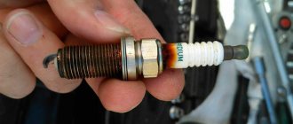
As for the circuit, the optical ignition on IZ Jupiter 5 or any other SZ is mounted using spare parts and fastening components that are included in the kit. As you know, the mechanism is designed to ignite the air-fuel mixture. The mixture itself, which is located in the engine cylinder, ignites thanks to a spark formed between the electrodes of the spark plug. It's no secret that the quality of the functioning of the safety system largely affects the operation of the entire vehicle.
As practice shows, one of the problems of IZhs is that the advance angle periodically gets lost. This is due to wear on the cams, as well as the contacts of the interrupter device. It should be noted that mechanical influences in electronic SZ are completely absent.
The pulse is removed in a separate block, and the signal goes to the switch, where it is amplified. Subsequently, the pulse arrives at the coil, then everything happens as usual. A discharge is applied to the spark plug, which causes the mixture to ignite, causing the crankshaft to start moving. Replacing a device or adjusting it at home is not so difficult, but you need to remember that incorrect actions can lead to possible malfunctions in the future.
There is no need to greatly alter the wiring, you just need to remove the contacts
(hammer and anvil), replace the coil, but first things first.
1. You need to purchase materials
A) Hall sensor - sold in almost every auto store ~ 50-70 rubles b) Switch - buy in the same place as the sensor ~ 200-600 rubles price depends on the country of manufacture and additional functions. It's a good idea to get a switch like this
D) One silicone armored wire ~ 50 rub. look in the same place as everything else. e) CAR spark plug cap. Important, the original caps have a resistor, so they cannot be used!! ~10 rubles. e) Installation wires with a cross-section of at least 1 mm. g) It is advisable to take several dozen female-male connectors, which will facilitate installation. h) M7 stud and 2 nuts for it. it will be great if you take a brass pin, as it is less magnetized
I’m not talking about electrical tape and so on, because I think you can figure it out for yourself!
And most importantly, you need a modulator! You can make it yourself, or, preferably, sharpen it at a turner. The modulator is a disk 0.8-1 mm thick, which is attached to the generator shaft instead of contacts.
Http://fotki.yandex.ru/users/kamaz995/view/163476/?page=0
Sizes may vary, but the neckline MUST BE 120 degrees!
Installation
1.Remove the breaker contacts, coil, capacitor. 2. We put the switch in the right glove compartment, the coil under the tank.
3. Unscrew the generator bolt, together with the distributor cam. 4.Put a pin in its place. 5.Attach the Hall sensor. 5.1. We fasten the modulator, but do not tighten it!!! 6. Connect everything according to the following diagram
We simply solder the female connector to the wire, wrap it with electrical tape or cover it with a PVC pipe. 7. We put the armor wire on the spark plug, connect it to the coil, and IMPORTANT! you need to connect it all hermetically, that is, with sealant, or put rubber bands. 8.If you have a tachometer, then connect it too. 9.Checked the connections again, is everything correct? Is everything tight??
Everything should have turned out roughly like this: https://fotki.yandex.ru/users/kamaz995/view/163474/?page=0
Only taking into account that there is one slot on the modulator (Yupak in the photo)
10. Turn on the ignition. 11.If you installed the switch I recommended, then just wait about thirty seconds until the rpm values of 1000,2000,3000,4000,5000 appear on the tachometer.
Congratulations! The commutator and coil work as they should. If there is no tachometer, just look at the spark plugs, which we once grounded to ground!
If the switch is not like that, take a screwdriver, insert it into the slot of the hall sensor and pull it out. At this moment there should be a spark.
12. We put the piston at TDC, move it to 3.5 mm, connect a voltmeter to pins 2 and 3 of the hall sensor, and slowly turn the modulator (not too tight!) when the voltage at the contacts drops from 7 to 0.1 volts, tighten the modulator, check the angle again , because it may not work out the first time. Now we screw in the spark plugs, pump up the gas, start it up, bang on, smooth engine operation, idle 500 rpm, excellent battery charging. Congratulations, now you also have a BSZ.
Finally, a few tips:
1. Do not allow the BSZ to operate with the battery disconnected. Check the reliability of the battery connections!! 2. Under no circumstances remove the spark plugs while the ignition is on. 3. If, when installing the generator cover, the BSZ completely refuses to work, swap the generator winding brushes. 4. Check the on-board voltage with the engine running. A strong scatter of parameters can affect the operation of the BSZ, or even damage it (if the voltage exceeds 16 V).
Good luck to everyone on the roads!!
Electronic ignition (BSZ) on IZ Jupiter
If you install BSZ on IZ Jupiter
, then even with domestic technology you can forget about the ignition problem altogether. And the engine, in turn, will run much smoother, softer, and the dynamics will improve! At speed, the engine will become much more sensitive to gas, and idling will be smoother and more stable. And it starts easily even with a fairly weak battery.
Installation of contactless ignition on IZH JUPITER
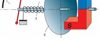
Nothing is changed on the generator: the cams are simply removed and a Hall sensor is attached in a suitable place. The plate - the modulator is fixed on the rotor - so that it passes clearly in the middle of the slot of the Hall sensor, placement issues are resolved with the help of washers. How everything is placed can be seen in the pictures. Non-contact ignition circuit (BSZ) IZH JUPITER
Modulator plate: This is where the whole secret of stable operation of the Jupiter engine with one Hall sensor lies.
Gaps in spark formation in some cases are associated with incorrect design of the curtain modulator (magnetic flux switch). Pay more attention to its location in relation to the sensor. When open, the shutter should not block either the magnet or the magnetic circuit (the metal “beak” at the end of the sensor); when closed, the modulator should completely block both of them. Otherwise, the sensor will produce fuzzy signals that the switch will not be able to recognize, and this is fraught with omissions in spark formation, and, consequently, malfunctions of the motor.
The modulator should be made in the form of a disk with a cutout made of steel 0.8-1.0 mm thick, as shown in the figure. The main thing is that the ratio of the periods of the closed state of the sensor to the open state is 2:1 (this is a prerequisite for the smooth operation of the switch control chip). If the engine is 1-cylinder, then the cutout angle in the modulator should be approximately 120 degrees, but if the engine is 2-cylinder, then the cutout angles should be 60 degrees. It is also important to note that the minimum cutout width is 11mm. When setting the ignition timing, remember: the spark strikes when the modulator “opens” the sensor.
Before installing the BSZ on IZ Jupiter
Make sure there is no excessive play in the generator shaft. This “carrier” of the curtain must fit within an axial runout of up to 0.35 mm, and its swing in the transverse plane is limited to 0.5 mm. Modulator blades that move beyond these standards will not fit into the narrow slot of the sensor and will smash the fragile plastic housing of the Hall sensor to smithereens. The bumpiness is most often caused by wear of the generator bearings - change them without hesitation, especially since contact ignition is also not friendly with backlash and will not be able to work smoothly.
Setting up non-contact ignition (BSZ) IZH JUPITER
When you start setting up the ignition on the Izh Jupiter
It may be difficult to adjust the ignition timing. But there is nothing complicated here! You can’t get into electronics with a traditional light bulb for setting contacts - a “dialer”. A voltmeter solves the problem - I’ll tell you how to use it.
I advise you to use a device with a scale of at least 15V and an internal resistance of 10-50 kOhm. Connect it to the terminals of the Hall sensor: place the positive wire on pin No. 2, and the negative wire on No. 3. Set the piston of any cylinder to the position corresponding to the moment of spark formation. Turn on the ignition and turn the modulator (as the crankshaft rotates) until the voltmeter readings change. The moment of discharge on the spark plug corresponds to a voltage surge in the sensor from tenths of a volt to a value close to the on-board power supply of the motorcycle. Having “caught” the spark, without disturbing the position of the curtains, fix the modulator on the generator shaft with a fastening bolt.
It must be remembered that when adjusting the ignition, be sure to short-circuit the high-voltage wires to the engine body or “load” them with spark plugs. Operating a coil with a broken secondary circuit leads to overload and damage to the BSZ. For the same reason, you cannot “turn off” the engine or one of its cylinders by removing the spark plug caps. If you want to visually verify the presence of a spark, do it as follows. Fasten the wire to be tested (by the insulated part) 5-8 mm from the engine body, turn on the ignition and press the kick. Once you set the advance, you will forget about the voltmeter for a long time. Check the serviceability of the Hall sensor using a method similar to setting the “angle”. But it is not necessary to rotate the crankshaft - it is enough to insert a steel plate, for example, the tip of a screwdriver, into the sensor slot. A working Hall with an “open” passage produces 0.2-0.4 V, close the “damper” - the voltage in the circuit should be at least 7 V.
Operation of contactless ignition (BSI) and problems
For some reason, many are sure that the red wire of the sensor from the switch is supplied with the same 12 volts that it is “powered by”, and based on these considerations, they connect the sensor not to the switch connector, but to the on-board network of the motorcycle. The voltage there, of course, is the same, but it is only passed through the system for protecting the sensor from power surges, which makes its operation more precise and uninterrupted.
Switch for contactless ignition (BSZ)
A switch is a complex, expensive and non-repairable device; it does not forgive incorrect connections. Buying a ready-made “switch-sensor” harness in a store (especially since it costs about 60 rubles) is much cheaper than replacing a damaged “brain”. There is not enough space on the motorcycle, my hands are itching to remove the radiator from the switch. This cannot be done, since within ten minutes the switch will overheat and die.
Another good tip: if you decide to redo the ignition on Jupiter, then all the parts should be “from the same place” (sensor, switch, harness and coil). It is better to take a coil for 1-cylinder vehicles 3112.3705 from front-wheel drive Zhiguli, and for 2-cylinder vehicles - a two-spark 3012.3705 (from a modern Volga or Oka). Do not check the spark between the high-voltage wire and the ground; look for the spark only on the spark plug (which should have good contact with the ground at the time of testing). If you move the wire too far from ground, the voltage in the secondary winding of the coil, trying to break through the excessive air gap, will exceed reasonable limits, and a spark will jump inside the ignition coil and disable it. But since the coil is essentially a transformer, the voltage will also increase in the primary winding. And the output transistor of the switch may not withstand this. If it burns out, the switch cannot be restored.
Having carried out all of the above, you will be pleasantly surprised that the ignition on the IZ Jupiter is non-contact
, now you have it too!
Miniatures
Electronic ignition of the IZH-Jupiter motorcycle with one Hall sensor.
Due to your numerous requests, I decided to write a short article about my electronic ignition. I installed it on my Jupiter a year ago, I tinkered with the installation, but it was worth it. I forgot what ignition is in general (it’s not even afraid of dampness!), the engine began to run much smoother, softer, dynamics improved, at speed the engine became much more sensitive to gas, idling was smoother and more stable. It starts even with a fairly weak battery. Having left the season and not having experienced any troubles, I immediately installed the same ignition on a new “watery” engine (I wrote about it in my previous article. So, in order. Installation and configuration took one day, all the details (I used the Hall sensor, bundle of wires, switch and two-terminal ignition coil from Oka. I didn’t change anything on the generator: I just removed the cams and secured the Hall sensor in a suitable place. The plate - the modulator is fixed on the rotor - so that it fits clearly in the middle of the slot of the Hall sensor , used washers. How everything was placed can be seen in the pictures
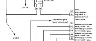
The wiring diagram is shown in the following figure. I think that comments are unnecessary, especially since the diagram is color. The only thing is that a voltmeter is completely unnecessary and you can safely throw it away - it only shows the voltage in the on-board network.
Modulator plate: This is where the whole secret of stable operation of the Jupiter engine with one Hall sensor lies. Gaps in spark formation in some cases are associated with incorrect design of the curtain modulator (magnetic flux switch). Pay more attention to its location in relation to the sensor. When open, the shutter should not block either the magnet or the magnetic circuit (the metal “beak” at the end of the sensor); when closed, the modulator should completely block both of them. Otherwise, the sensor will produce fuzzy signals that the switch will not be able to recognize, and this is fraught with omissions in spark formation, and, consequently, malfunctions of the motor. The modulator itself should be made in the form of a disk with a cutout made of steel 0.8-1.0 mm thick, as shown in the figure. The main thing is that the ratio of the periods of the closed state of the sensor to the open state is 2:1 (this is a prerequisite for the smooth operation of the switch control chip). If the engine is 1-cylinder, then the cutout angle in the modulator should be approximately 120 degrees, but if the engine is 2-cylinder, then the cutout angles should be 60 degrees. It is also important to note that the minimum cutout width is 11mm. When setting the ignition timing, remember: the spark strikes when the modulator “opens” the sensor. Before installing the BSZ, make sure that there is no excessive play in the generator shaft. This “carrier” of the curtain must fit within an axial run of up to 0.35 mm, and its swing in the transverse plane is limited to 0.5 mm. Modulator blades that move beyond these standards will not fit into the narrow slot of the sensor and will smash the fragile plastic housing of the Hall sensor to smithereens. The bumpiness is most often caused by wear of the generator bearings - change them without hesitation, especially since contact ignition is also not friendly with backlash and will not be able to work smoothly. Setting up: At first I had difficulty setting the ignition timing. You can’t get into electronics with a traditional light bulb for setting contacts - a “dialer”. The voltmeter helped me out - I’ll tell you how to use it. I advise you to use a device with a scale of at least 15V and an internal resistance of 10-50 kOhm. Connect it to the terminals of the Hall sensor: place the positive wire on pin No. 2, and the negative wire on No. 3. Set the piston of any cylinder to the position corresponding to the moment of spark formation. Turn on the ignition and turn the modulator (as the crankshaft rotates) until the voltmeter readings change. The moment of discharge on the spark plug corresponds to a voltage surge in the sensor from tenths of a volt to a value close to the on-board power supply of the motorcycle. Having “caught” the spark, without disturbing the position of the curtains, fix the modulator on the generator shaft with a fastening bolt. I must warn you that when adjusting the ignition, be sure to short-circuit the high-voltage wires to the engine body or “load” them with spark plugs. Operating a coil with a broken secondary circuit leads to overload and damage to the BSZ. For the same reason, you cannot “turn off” the engine or one of its cylinders by removing the spark plug caps. If you want to visually verify the presence of a spark, do it as follows. Fasten the wire to be tested (by the insulated part) 5-8 mm from the motor body, turn on the ignition and press the kick. Do not try to fix the wire with your hands - it will jump so hard that sparks will fly out of your eyes. However, this effect is also indisputable proof of the efficiency of the ignition. Once you set the advance, you will forget about the voltmeter for a long time. Check the serviceability of the Hall sensor using a method similar to setting the “angle”. But it is not necessary to rotate the crankshaft - it is enough to insert a steel plate, for example, the tip of a screwdriver, into the sensor slot. A working Hall with an “open” passage produces 0.2-0.4 V, close the “damper” - the voltage in the circuit should be at least 7 V.
Operation and problems: For some reason, many are sure that the red wire of the sensor from the switch is supplied with the same 12 volts that it is “powered by”, and based on these considerations, they connect the sensor not to the switch connector, but to the on-board network of the motorcycle. The voltage there, of course, is the same, but it is only passed through the system for protecting the sensor from power surges, which makes its operation more precise and uninterrupted. Now about switches. The devices are not simple, expensive and cannot be repaired; they do not forgive incorrect connections. Buying a ready-made “switch-sensor” harness in a store (especially since it costs about 60 rubles) is much cheaper than replacing a damaged “brain”. There is not enough space on the motorcycle, my hands are itching to remove the radiator from the switch. This cannot be done, since within ten minutes the switch will overheat and die. Another good piece of advice: if you are going to redo the ignition, then all the parts should be “from the same place” (sensor, switch, harness and coil). It is better to take a coil for 1-cylinder vehicles 3112.3705 from front-wheel drive Zhiguli, and for 2-cylinder vehicles - a two-spark 3012.3705 (from a modern Volga or Oka). Do not check the spark between the high-voltage wire and the ground; look for the spark only on the spark plug (which should have good contact with the ground at the time of testing). If you move the wire too far from ground, the voltage in the secondary winding of the coil, trying to break through the excessive air gap, will exceed reasonable limits, and a spark will jump inside the ignition coil and disable it. But since the coil is essentially a transformer, the voltage will also increase in the primary winding. And the output transistor of the switch may not withstand this. If it burns out, the switch cannot be restored. When writing this article, materials from the magazine “Moto” were used.
You can ride a motorcycle without worrying about its technical condition. But the owners of the “iron horse” love their cars, take good care of them, carry out the necessary maintenance, showing true care for their beloved friend.
Modernization brings a lot of pleasure to the owners of this type of transport. Many people have one dream - to install contactless ignition. “Ancient” contact-type systems have long since become obsolete. They are no longer used on modern motorcycles and cars. One headache:
- loss of gap between the contacts of the breaker;
- changing the geometry of contacts;
- not constant sparking;
- failure of high-voltage wire insulation;
- unstable operation of the high-voltage coil;
- impossibility of starting the engine when the battery voltage is low.
- the spark does not ignite the combustible mixture in the engine cylinder
Electronic ignition on Izh Jupiter 5 with a Hall sensor allows you to completely get rid of these shortcomings.
In what cases is ignition adjustment necessary?
During the operation of the vehicle, the owner faces many problems. The most serious failure is related to the engine. In order to spend significant funds on major repairs, it is necessary to monitor the technical condition of the motorcycle and carry out preventive work, including adjusting the valves and valves (video author - Hana Rulyu).
If you do not monitor the SZ, then the motorcycle engine may not reveal its full potential and will not work at full capacity. This can lead to a reduction in its service life. An ignition adjustment is necessary if the engine is running poorly, the muffler or carburetor is firing. True, before setting up the SZ, you should make sure that the cause of the malfunction is in it.
It happens that the flywheel bolt, which connects the two halves of the crankshaft, comes loose, begins to play and does not work well. Sometimes he even cuts the key.
Setting up the SZ may be necessary after repairing lock 5. The installation and connection itself are carried out according to the diagram.
Electrical circuit diagram of the IZH Planet Sport motorcycle
How to make the transition to contactless SZ? When the engine is switched off, the indicator lights up, and when the engine is running, it goes out.
How can I modify the generator? After long-term use, the ignition circuit of IZ Jupiter 5 is changed by the owners to systems from other Soviet motorcycles.
The turn signal switch is located on the frame under the gas tank.
Wiring diagram for IZH Jupiter 5 The bike of the fifth Jupiter has a contact SZ, which is battery-powered, so the operation of the vehicle is highly dependent on the state of charge of the battery. Install the generator in reverse order.
Burnt contacts, oily spark plugs and batteries with a charge of less than 12 V further worsen sparking. An additional coil is used as an exciter. Charging IZH
Related article: Checking the loop resistance phase zero
Scooter ignition
Ignition from a scooter on the Izh Jupiter can work without a battery. Before setting it up, we need three details:
- Scooter switch;
- Ignition coil;
- Inductive original sensor (must have a single wire output).
The DC switch is powered from a 12 W network, also the on-board network of the motorcycle is 12 W, the switch has 4 wires, the first of which is plus, the second is minus, the third is to the coil, the fourth is to the inductive sensor. We reliably connect the negative wire from the switch to the negative wire from the motorcycle (ground), and connect the positive wire that goes to the standard coil to the positive wire of the switch.
Ignition coil connection:
- We connect the negative wire to the ground of the motorcycle;
- we stretch the second wire to the switch and connect it to the output under the coil
In order not to pull an additional wire to the inductive sensor through the entire engine, you can use the wire that connected the contact group and the standard ignition coil.
To do this, you need to take the wire from the switch that goes to the inductive sensor and connect it to the wire that went to the standard coil. Next, remove the capacitor and connect the inductive sensor. Particular attention must be paid to positioning the generator cover. It needs to be installed properly and not touch anything when rotating.
To do this, you need to shorten the cam a little and also make notches on it that prevent the modulator itself from turning. It is also worth observing the parameters of the gap between the modulator and the inductive sensor, which should be within 1-1.5 mm. When installing the ignition, you need to know that the spark strikes when the modulator leaves the sensor, and not at the input.
Once electronic ignition from a scooter is installed on a motorcycle, its performance will improve significantly. In particular, it will start much better (this will be especially noticeable when the battery charge level is low). Speed gain will also improve noticeably. The motorcycle will idle smoothly, which indicates proper engine operation.
( 2 ratings, average 1 out of 5 )
How to correctly set the ignition on Jupiter 5
Home » Articles » Automotive articles » How to correctly set the ignition on Jupiter 5 Today, the Jupiter 5 motorcycle model is one of the latest in this brand and is still popular. This is due to the affordable price and ease of technical setup. But unfortunately, the model has a drawback - a two-cylinder engine with a short resource, which requires ignition adjustment. How to set the ignition to Jupiter 5 will be discussed in the article.
Contactless ignition
- We unscrew the candles. There is no need to remove them from the caps. You just need to lean them on the ribs of the cylinder.
- Now you need to catch the crankshaft at the dead point of one piston. It should be rotated back so that the piston drops 2.6 mm.
- In this case, the modulator must be in free rotation. Due to this, with the ignition in the “on” position, the moment of spark formation is “caught”.
- And after that, the resulting position is fixed by pulling the modulator.
- We carry out all the manipulations from steps 1 to 3 with the second cylinder. After setting it to 2.6 mm, you need to rotate the crankshaft by the generator nut.
If a coincidence occurs, then everything was done correctly. If not, then proceed as follows:
- late ignition - loosen the control modulator nut and act according to scheme 1–3;
- early ignition - grind the modulating edge until the desired effect is obtained (until the spark on the spark plug appears at the right time).
Contact ignition
How to set contact ignition on Jupiter? Some of the models left the factory with contact ignition. To set it up, you need to prepare: screwdrivers, a 12V light bulb with two wires coming from it, a caliper, a spanner and an open-end wrench.
- First you need to remove the cover. This will open access to the ignition mechanism.
- Then unscrew all the spark plugs and place them in the cylinder located on the right; insert a screwdriver instead of one.
- Now you need to turn the nut (located in the center) connected to the crankshaft. The piston is placed in m.t. (above). M.t. is at the maximum protrusion of the screwdriver (the position is fixed with a mark).
- The next step will require help. It is necessary that one person holds the screwdriver, and the other on the m.t. Using a caliper, I noted the coincidence of the instrument scale with the mark.
- Now we ask an assistant to turn the crankshaft counterclockwise.
On the body of the caliper we mark the lowering of the screwdriver at 2.6 mm. This is how the advance is adjusted.
When aligning the piston, pay attention to the ignition cams (which one is open). The lamp contacts are applied to it: to ground and to the cam. Release the fixing screw and begin to rotate the adjusting screw. As soon as the lamp goes out, the moment is caught. At this stage, the adjusting screw is held, and then it is tightened with a fixing screw
The setting of the first cylinder is completed. Proceed to the second according to a similar scheme
At this stage, the adjusting screw is held, and then it is tightened with a fixing screw. The setting of the first cylinder is completed. Proceed to the second one using a similar scheme.
Conclusion
It is possible to set the ignition correctly on Jupiter 5, but this motorcycle, despite its simplicity, is a rather demanding mechanism. A lot depends on the ignition setting: speed range, engine power and fuel consumption. Knowing how to set up contact and non-contact ignition, you can always stay on top. And for those who do not have enough instructions, we invite you to familiarize yourself with the material: how to set the ignition on Jupiter video.
Setting the appropriate options
Setting up the BSZ on Izh Jupiter 5 also requires special attention. The ignition is turned on with the tachometer connected. After thirty seconds, indicators of 3000, 4000, 5000 rpm should appear on the device panel. If they are present, then the switch is working correctly.
In other cases, you should pay attention to previously grounded candles. We insert a screwdriver into the hall connector, and then pull it out
A spark should appear on the spark plugs. If it was not possible to cause a spark using the steps described above, then the reason for the incorrect operation is incorrect connections.
The setup looks like this. The dial indicator is unscrewed and the cylinder piston is adjusted. Having connected the voltmeter to the second and third connectors, you need to start rotating the modulator axis. After a jump from 7 to 0.1 volts is detected, the modulator must be secured with a nut. Usually the required advance angle is set.
The test run should be successful if you install the components yourself according to the instructions. Now you can use BSZ.
The main problem with the Izh Jupiter motorcycle engine is the standard contact ignition system. Any owner of Jupiter sooner or later faces the problem of failure of one of the cylinders due to a change in the gap in the contacts or failure of the capacitor. Adjustment helps, but usually not for long. This problem can be radically solved by installing a contactless ignition system on a motorcycle.
Single-channel BSZ.
There are probably many options for BSZ design, but we won’t consider them all. Let's focus on the simplest, and probably the most common option in our country. There is no motorcycle market or motorcycle store nearby where you can buy a factory-made BSZ, and there is no turner with a machine nearby either. We will proceed from this.
Minimum set for installation
But we can’t do without a minimum set, so before you start work, you need to stock up on the following components, which are sold in any auto shop or car market in our country:
1. Switch from VAZ 2108
2. Hall sensor from VAZ 2108
3. Set of wires for BSZ from VAZ 2107 (from distributor (Hall sensor) to switch)
4. Two-terminal ignition coil (from an Oka or Gazelle car with a ZMZ 406 engine)
5. Two automotive silicone high-voltage wires of the required length with caps for spark plugs (you can buy a kit for a VAZ and take it from there, you can simply find used wires, after first making sure they are working)
Next, in addition to the components, we will need a small flat piece of sheet steel 1-1.2 mm thick to make a modulator and a plate for the Hall sensor. I warn you right away that stainless steel or non-ferrous metals are not suitable for the manufacture of the modulator, since they are not magnetic materials. To make a plate for the Hall sensor, you can use any material of sufficient strength.
Tools you may need are a drill with drills, files, a chisel, a hammer and other tools that, as a rule, are found in any garage.
Rework process
We dismantle the old ignition system. We remove the plate with contacts, capacitors, ignition coils with high-voltage wires from the motorcycle. We install the switch in the right glove compartment.
We attach the ignition coil to the frame under the tank. We connect the wiring connector to the switch, connect the black ground wire from the connector to ground. We connect the wire from terminal No. 1 of the switch connector to one of the coil terminals. We connect the second terminal of the coil to the old wiring, to the wire to which “+12V” is supplied when the ignition is turned on. In the old wiring, this wire connected both ignition coils. From it we pull an additional “+12V” wire to the switch, which we connect to the 4th wire in the connector. We carefully isolate everything. We insert the wire with the connector to the Hall sensor into the cavity of the generator.
You can check the functionality of the system. We connect the Hall sensor to its connector, connect the high-voltage wires to the coil and to the spark plugs. We provide reliable weight to the candles. Turn on the ignition and pass a metal object (you can use a flat screwdriver) through the Hall sensor slot. The spark plugs should spark. The scheme is working. (If there is no spark, then something is connected incorrectly and everything needs to be checked again.) Now it remains to supply a spark at the right time to the cylinders, for this:
Contactless ignition on Izh - understanding unclear terms
- BSZ
- contactless ignition system; - Modulator
- metal disk (steel 0.8-1.0 mm thick), plate, curtain. Installed on the axis of the ignition timing mechanism (distributor shaft). Produces “generation” of magnetic pulses to the Hall sensor. - Switch
- an electronic device that supplies electrical impulses to the ignition coil; - A Hall sensor
is a device capable of detecting the presence or absence of a magnetic field. If there is a field, a control pulse goes to the switch. The sensor position is fixed. - The ignition coil
is a converter of pulses coming from the switch into high-voltage pulses supplied directly to the spark plugs.
How to set the ignition?
When setting up the ignition, problems often arise with setting the signal advance angle. A voltmeter will help fix this problem. Looking ahead, it should be said that a device designed for a minimum of 15 V and 10-50 kOhm (internal resistance) is ideal. A voltmeter is connected directly to the terminals. Next, you should bring the piston to the position at which sparking occurs. Then turn on the ignition and turn the modulator until the readings on the device change. You can track the charge on the spark plug by the voltage on the sensor, which should jump. This value is equal to tenths of a volt close to the on-board power supply of the equipment. As soon as the spark is “groped”, you need to fix the position of the modulator directly on the generator shaft. This is usually done with a bolted connection. When adjusting the ignition, constantly short-circuit the high-voltage wires to the frame of the unit. Otherwise, excessive load on the ignition cannot be avoided, which can lead to its failure.
System assembly and installation
The contacts in the breaker, the capacitor, the ignition bobbins and the armor wires, which are part of the previous ignition device, are probably eliminated. The switch should be installed in the glove compartment on the right, and the ignition coil directly under the tank. There are no gaps for fastening on the reel, which means it can be attached using a thick layer of adhesive tape. The standard bolt is also eliminated along with other parts.
In place of the bolt, install a pin of the specified size and put on a washer. Then, the rotor is tightened with a nut located at its end. The hall sensor is attached to the stator by any means. The basic rule when installing it is to set the optimal cross-sectional distance of the modulator and the ratio of the radius and line of symmetry.
When the hall sensor can be secured, we apply the modulator. It should fit into the hole made in the sensor. In most situations, there is a discrepancy between the sizes, so it is necessary to place washers on the stud. If you manage to maintain the required gap, it is recommended to install an engraver and tighten the modulator with a third-party nut.
Required Parts
Correctly setting the equalizer on a Sony radio
In order for the ignition system to work correctly, a number of auxiliary parts are required. They are listed below:
- Switch for BSZ VAZ cars. You should not choose exclusively from the low price segment. The Astro switch has a lot of positive reviews;
- Hall Sensor. The best option for Jupiter 5 is a similar manufacturer VAZ. By purchasing it in branded packaging, you protect yourself from counterfeits;
- Ignition coil with two terminals. You should choose between the gazelle engine number 406 or Oka with an electronic ignition system;
- A pair of silicone armor wires with rubber caps;
- The modulator is a butterfly-shaped plate made of iron.
Modulator
The most difficult stage is the production of the modulator
It is important to maintain the required shape. The more reliably the required dimensions are observed, the lower the likelihood of problems occurring after implementing the system, that is, there will be no need to adjust it using a file
The ignition timing must match on any cylinder used.
The bolt hole must be located in the middle. Otherwise, the engine operation will not be synchronized. It is also recommended to check the integrity of the crankshaft bearings. If you find defects, you should immediately replace it.
The contact ignition is not able to work normally if the bearings are damaged. The thickness of the part should not exceed one and a half millimeters. If it is thin, it will not be possible to avoid deformation, and if it is thick, it will come into contact with the surface of the hall sensor housing.
To create the plate, it is allowed to use any material except steel. Aluminum and others should not be used as they are not magnetic. The drawing that must be followed can be found in the public domain. The presented diagram will be useful to those people who decide to modernize the vehicle ignition device. Below are methods for installing electrical ignition devices in Jupiter.
It must be turned by a professional turner. He will make a simple disk and draw on it the markings of elementary distances between the corners. Then, in accordance with it, you will cut out the necessary sectors at home. The cost of the modulator is seventy rubles.
It is not advisable to use an ordinary plate, since its width is less than twelve millimeters. This will not be enough to fully accumulate the energy resource in the coil. Of course, it can be installed, but achieving four thousand revolutions per minute will become impossible.
In addition to the above you will need:
A stud with an applied thread of seven millimeters, pitch 1, as well as a pair of nuts with washers of the corresponding parameters. The priority material for these components is brass. This is explained by the least magnetization of the plate from the generator rotor.
If you use a standard bolt, then difficulties may arise with the implementation of the ignition. The bolt tends to follow the modulator as it is tightened. However, it is necessary to observe the leading indicator, maintain the same position of the rotor and modulator, and tighten the bolt. It is advisable to use a pin, since many are not able to perform all the necessary actions in total;
A set of wires with connectors for ignition without contact from VAZ. This part can be purchased or made with your own hands.
Generator
The motorcycle is equipped with a 3-phase alternator, which has an electromagnetic excitation circuit. The principle of its operation is based on some features. So, the electrical circuit of “IZH Planet-4” looks like this: the current is supplied to the rectifier, which, in turn, converts it into direct current, then supplies it to consumers. The factory instructions for the generator contain the following elements:
Voltage regulator with rectifier “BPV-14-10”;
The head light circuit consists of the rear brake light, parking light and color control light. The motorcycle is equipped with a speedometer with mileage indicators (daily and total), a tachometer, indicator lamps for turn signals and head lights, a voltmeter and an engine temperature sensor. Very often during operation it is necessary to adjust the gap between the contacts of the breaker. To do this, it is best to use a diagram and special tools to know which elements need to be dismantled.
While easily fixing mechanical failures, motorcyclists experience difficulties if the electrics fail. It’s completely in vain, the wiring diagram of the planet Izh 5 is not complicated, it’s easy to figure out.
There is no need to have special stands and equipment for repairs. A minimum knowledge of electrical engineering and a simple avometer (tester) is enough; even often you can get by with just a test lamp.
We will tell you in more detail about the main electrical wiring components and possible malfunctions. The Izh Planet wiring diagram makes it easy to find a broken wire or damaged insulation (for example, a bad contact always gets hot).
In this case, we look to see if there is a spark at the coil output and at the output at the spark plug contact. Let's take a closer look at the main wiring components of the Izh Planet.
Setting up contact ignition on Izh Jupiter - 5
Let's take a step-by-step look at how to set up contact ignition on this device:
- Align the piston of the desired cylinder: - insert a screwdriver into the cylinder - rotate the crankshaft while holding the screwdriver
- Take a ruler and place it next to the screwdriver.
- Rotate the crankshaft, holding the screwdriver down with your finger so that it is level. We find a dead point.
- Turn the crankshaft in the opposite direction (1.5-2 mm).
- A spark is generated when the cam opens, locate the two adjusting bolts.
- Take a light bulb with two contacts, connect one to ground, the other to the contact.
- Turn on the ignition switch.
- You need to find the moment when the light comes on (the moment it lights up, the start occurs), and when it goes out, the contact closes on the contrary.
- Turn off the ignition, do and adjust the same with the second cylinder
Guide to setting up BSZ on a motorcycle
How to install electronic ignition on Izh Jupiter 5
To configure the system on a motorcycle, it is advisable to use devices with a scale of up to 15 volts and an internal resistance of up to 0 kOhm. Thanks to the electronic device, adjusting the unit will not take much time and effort. The terminals from the device must be connected to the Hall sensor. The procedure for setting up contact ignition without using auxiliary devices is shown in more detail in the video below (the author of the video is the Han Rulyu channel).
So, for proper tuning, place the cylinder piston in a position that provides the most optimal spark formation. Any cylinder can be used. Then the ignition is activated, and the modulator device must be turned in the direction of movement of the rotor with the crankshaft. Rotation is carried out until changes are visible on the voltmeter screen. At the moment when you can catch a spark, the position of the curtains should not be changed. As for the modulator device, it must be securely fastened to the generator shaft; a fastening screw is used for this.
During setup, you should in any case short-circuit the high-voltage circuits to the motor housing. This is done so that when using a short circuit, the system does not overload, which can ultimately lead to failure of the BSZ. In addition, the engine cannot be stopped when removing the spark plug caps.
After the adjustment is made, the performance of the system must be checked. If you place the cable being tested approximately 7-8 mm from the power unit and then try to start the engine, a spark should jump out. As you can see, in general, the procedure for setting up a node is not particularly complicated, but it requires care and the right approach, so the above recommendations are still worth considering. In addition, one should not forget about safety precautions, since incorrect actions can lead to a short circuit in the wiring and failure of the unit as a whole.
Main stage
As noted in the assembly diagram of the Izh-Planet 5 box, further disassembly operations are carried out above the insides of the roof of the unit, since the secondary shaft and sector could remain in it. If it is necessary to remove them, you need to straighten the petals of the lock washer, unscrew the nut, remove the star and washer. Holding the gear very carefully to prevent the shaft from jumping out, the cover is moved to a clean and flat surface with the gear facing up.
It is worth noting that the bearing of this part of the assembly does not have a retaining ring. Therefore, when removing the shaft with bearing, the rollers may fall out, so be careful. If the specified element has exhausted a decent service life, there is a risk that when dismantling the secondary shaft, the outer ring may jump out of the seat and remain on the rollers. Next you need to start pressing out the oil seal. To do this, the installation rings are removed from the hole in the cover, after which the outer ring of the bearing is removed.