Replacing the rear spar of VAZ 2105/07 cars
Spars on VAZ “classic” cars, i.e. VAZ from the first to the seventh models have the same design. The weak points of these side members are the mounting points for the steering mechanism, cross beam, stabilizer bar mounting and on the right side of the pendulum mounting. By design, these places cannot be called weak, since it is in these fastening points inside the spar that amplifiers are installed, but they also do not withstand our road conditions and the service life of these vehicles.
Since the beginning of this spring, several cars have already been received for repair of side members at the place where the beam is attached and the steering mechanism is attached. Basically, cracks on the side members are discovered by technicians when diagnosing the chassis and refuse to adjust the wheel alignment angles until these defects are eliminated. The main cause of cracks is loose fastenings, road conditions, and, as they say, metal fatigue.
Most often, the rigidity of the steering mechanism fastening on the left front spar is broken and a crack appears in the area of the lower mounting bolt, resulting in a backlash of the body relative to the spar, which significantly affects the violation of wheel toe adjustment. In the initial stage, there may not be a crack, but play has already appeared, this indicates that there is a crack on the amplifier, inside the spar. All this means that this defect cannot be eliminated by simple welding on the outside of the spar, and it is impossible to weld along the mounting plane, since the correct installation of the steering mechanism will be disrupted.
In this situation, an operation is required to penetrate the internal cavity of the spar, the procedure for which we will familiarize ourselves with.
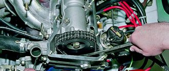
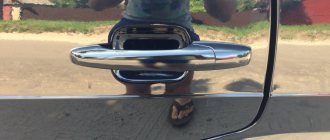
The internal steering gear mounting reinforcements can be accessed from the mudguard side; in this case, you need to remove the left front wheel and unscrew the lower steering gear mounting bolt without completely disconnecting it.
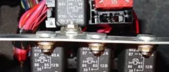
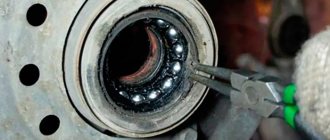
We drill out several welding points (the number of points depends on the required size of the window, in our case there are 4 of them) and cut them out with a grinder as shown in Figure 1. We cut them down along the edge. As can be seen in Figure 2, a second layer has appeared - this is an amplifier, which also needs to be removed.
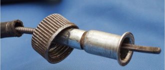
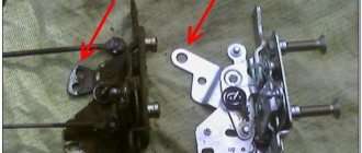
Around the hole you can see three points that also need to be drilled - this is the fastening of the spacer sleeve to the inside of the amplifier and then open it. In this case, the spacer sleeve no longer held on the inner wall of the spar and was removed along with the amplifier plate, as we see in Figure 3.
And here is a crack that definitely had to be there and it is located on the amplifier, as a result of which the spacer sleeve broke off during welding at three points. Next, you need to weld everything and install the reinforcing lining of your design.
In order to accurately install the spacer sleeve, we tighten it with the same fastening bolt, only with a nut on the side of the steering mechanism, which is in its place and does not interfere with the repair of the spar. We weld the bushing with three points.
Next, remove the bolt and weld the window with the same overlays and through the drilled holes.
All that remains is to treat the welding areas with anti-corrosion materials, install the lower steering gear mounting bolt, install the front left wheel and the repair is complete.
In this case, the destruction of the spar was at the initial stage, so the window had to be cut to a minimum size and only one bolt was unscrewed. As they say, any treatment is always easier to carry out at the initial stage, and the result is always better.
There is 1 comment. to the topic: “Repair of the front side member on a VAZ 2101 - 2107”
How to make money: Tips
Develop your mining network bit.ly/2OOmu60 – CryptoTab – increase your income
Lone wolves only exist in books and westerns, but in life we rely on loved ones. With the CryptoTab browser you can earn money alone, but the most profitable thing is to create your own network of miners.
Income from the mining network
You will receive 15% of the amount of currency mined by invited users. Those whom they invite will bring you 10% - and so on until the 10th level of the network. If everyone who installed a browser using your link invites at least a couple of people, they will bring others, and others will bring third parties - your network will grow and begin to generate serious income. Earnings from a mining network may be more than from your main occupation! Invite people and you don't even have to mine yourself: we'll pay interest as long as at least one member of your network uses CryptoTab.
How to attract more miners
Among your friends and subscribers there will probably be those who want to earn income simply by using the browser. Tell them about CryptoTab! Share this post on Facebook, Reddit, LinkedIn, Twitter, Tumblr, Pinterest or another network. Publish a promotional post on your page, in groups and communities, or send a personal message.
On Facebook, you can share posts not only in your timeline, but also in groups - even those in which you are simply a member. Find communities with a large audience, publish promotional posts - and the growth of your mining network is guaranteed! Select “Share in group”, type the first letters of the name and find the desired group in the drop-down list.
Your contacts in WhatsApp, Telegram, Viber, Line and other messengers can generate profit! People are more willing to respond to messages addressed to them personally, so messaging in instant messengers may work better than posts on social networks. Send a short message that explains the benefits of mining with CryptoTab and how it works. Don't try to sound serious and formal, write in simple words: the same way you communicate in conversations and chats. And if you are not confident in your writing talents, use ready-made texts.
E-mail is a proven promotion channel that should not be ignored. Everyone has an email, and besides, you can say something in a letter that wouldn’t fit into a short message or post. Use logos, banners and other materials in your design bit.ly/2OOmu60 - CryptoTab Promo - this will make your letters more colorful and convincing. Don’t forget to greet the recipients, try to write briefly and to the point. Be sure to fill in the “Subject” field - otherwise the letters will end up in spam!
Use different links
Add several referral links to monitor the effectiveness of different promotion channels. Focus on those sites that bring more visits and installations; if the channel doesn't work, try other approaches.
Reasons for the destruction of side members
The main reason for the destruction of side members is metal fatigue, which occurs from the exposure of the car body structure to variable loads. As a result of the following factors, cracks may gradually appear in the side members (they may even burst, in which case they will need to be replaced):
- Poor quality of roads
- Corrosion processes
- Accidents
Cars, even SUVs, that are actively used in conditions of poor quality roads are especially susceptible to the destruction of side members. In this regard, the VAZ 2121, which in many ways “adopted the blueprint” of body parts from the “classic” VAZ 2106, endures the hardships of operation in off-road conditions especially hard. It cannot be compared in terms of strength with the same UAZ. A typical problem with the “classic” Niva is cracks in the front side members. To prevent the destruction of the side members, owners of Niva 2121 cars prefer to strengthen them in advance using specialized kits.
VAZ 2105 (Zhiguli)
A selection of body dimensions, data on body geometry and control points of the VAZ 2105 (Zhiguli) from factory documentation.
A significant part of body repair work is carried out on damaged vehicles, which in most cases require checking the geometry of the attachment points of components and assemblies of the chassis of the VAZ 2105 (Zhiguli) car.
0 – baseline; 1 – upper radiator mount; 2 – fastening the steering gear housing and the pendulum lever; 3 – axis of the brake and clutch pedals; 4 – center of the steering mechanism; 5 – center of the wheel; 6 – mounting of rear suspension shock absorbers; 7 – center of the rear technological hole of the central reinforcement of the trunk floor; 8 – rear mounting of the gas exhaust muffler; 9 – front muffler mount; 10 – fastening of the transverse rod of the rear suspension; 11 – rear wheel axle; 12 – axes of bolts for fastening the upper longitudinal rods of the rear suspension; 13 – axes of bolts fastening the lower longitudinal rods to the body brackets; 14 – fastening of brackets for lower longitudinal rods; 15 – center of the rear technological hole of the front spar; 16 – center of the technological hole of the front spar; 17 – center of the wheel; 18 – attachment points for the front suspension cross member; 19 – mounting of the anti-roll bar; 20 – lower radiator mount; 21 – car axle; 22 – upper radiator mount; 23 – front wheel axle; 24 – rear engine mount mount; 25 – fastening of the cardan shaft support; 26 – mounting of rear suspension shock absorbers
0 – reference line; 1 – intersection of the axes of the front anti-roll bar mounting bolts with the surfaces of the side members; 2 – center of the axes of the lower bolts securing the steering gear housing and the pendulum arm bracket; 3 – intersection of the centers of the front technological holes of the front floor with the surfaces of the side members; 4 – intersection of the rear technological holes of the front floor side members with the surfaces of the side members; 5 – center of the axes of the bolts for fastening the lower longitudinal rods; 6 – center of the mounting axes of the upper longitudinal rods; 7 – intersection of the axis of the crossbar mounting bolt with the body bracket; 8 – intersection of the center of the rear technological hole of the central reinforcement of the rear floor with the surface of the amplifier; 9 – center of the axles of the front anti-roll bar mounting bolts; 10 – intersection of the centers of the axes of the lower mounting bolts of the steering gear housing and the pendulum arm bracket with the surfaces of the side member mudguards; 11 – centers of the front technological holes of the front floor side members; 12 – centers of the rear technological holes of the front floor side members; 13 – intersection of the axes of the bolts for fastening the lower longitudinal rods with the outer surfaces of the body brackets; 14 – intersection of the axes of the bolts for fastening the upper longitudinal rods with the outer surfaces of the middle side members; 15 – intersection of the axis of the bolt securing the transverse rod with the body bracket; 16 – center of the rear technological hole of the central reinforcement of the rear floor; 17 – longitudinal axis of the car
Damage to the body can be very different. Therefore, the repair rules in each individual case must be their own, most suitable for these damages.
In almost all cases of damage, it is necessary to remove some parts in order to detect damage, straighten and align the frame. In cases of severe damage, remove all easily removable interior upholstery parts to facilitate measurement, control and installation of hydraulic or screw jacks to correct distortions and deflections.
By editing it is necessary to restore the original linear dimensions of the body frame.
The diagonal dimensions of window openings should be 1375±4 mm for the wind window, and 1322 4 (1322–2) mm for the rear window. The distances between the flanges of the window openings along the axis of the car must be equal to 537 3 mm for the wind window and 509 3 mm for the rear window.
The difference in the diagonal dimensions of the wind window opening, as well as the openings of the rear window, hood, and trunk lid of one body must not exceed 2 mm.
Most often, when repairing the frame, replacement of the fenders, roof panels, front and rear panels is required. Methods for replacing and repairing these parts can be used as a basis for repairing other frame parts. It is also necessary to know the location of the welds.
Method of strengthening spars
Overlays for strengthening the side members
The main way to strengthen the front side members on a Niva 2121 car is to install a ready-made set of linings. Those available for sale cost between 3000-4000 rubles, they look like semi-handicraft production. Here we simply reproduced a drawing of a part that is freely available. Agree that it’s impossible to think of anything more sophisticated in appearance and price for a budget car for off-road driving. The kit includes a reinforcement in the form of steel sheets (3 mm thick) and shock absorbers for brackets (4 mm thick). If you have excess free time, but no money, then you can make the overlay yourself; the drawing of the Niva 2121 spar overlay for KOMPAS can be freely downloaded on the Internet. But it is better to “cut out” the part based on a cardboard pattern, which can be made based on the existing spar. Then, using a 3mm thick steel sheet, the part is cut out with a grinder. Since you will still need access to them, we present an algorithm for dismantling the surrounding units of the Niva 2121.
How to access the side members
- You will need to drive the Niva 2121 onto an overpass or a lift. Then the wheels are dismantled.
- Remove the caliper by unscrewing the clamp
- Using the “lever” technique or a hammer, knock out the knot
- Loosen both shock-absorbing fasteners
- Hang the brake system cylinder on the hoses
- Removing the upper arm, upper bump stop and cup
- Releasing the gearbox and steering pendulum
So, let's move on to the next part of the work on strengthening the side members of the Niva 2121 - installing the linings:
Check the quality of the seat for the shock absorbers.
Note! Dismantling of the “house” is carried out by drilling the welded points. First, use a drill with a No. 5 drill. Then it’s the turn of the drill for No. 10. You can examine the points for welding only after thoroughly cleaning the metal around. You remove the house and then clean the surface of the spar to identify possible minor defects that may be there. Then clean again.
Note! The trim must be in close contact with the spar!
Correct replacement of the VAZ 2107 spar
This is the spar
The VAZ 2107 spar has problems:
- with a place for fixing the steering mechanism,
- with cross beam,
- with stabilizer bar mounts.
Amplifiers are installed in the above locations. But they are not able to withstand the load created by existing road surfaces and work out the entire service life characteristic of a given vehicle. Auto mechanics often discover cracks in the side members when repairing the chassis. In this case, the wheel mounting angles are not adjusted until the specified defect is eliminated.
The main reasons for the appearance of cracks are weak fastening, poor road conditions and “fatigue” of the metal used.
Purpose and tasks
The spar is literally the power part of the car. The purpose of the unit varies depending on the type of vehicle:
- In trucks and 4x4 cars, side members are the main unit that is part of the frame;
- In passenger vehicles, the task of the part is to strengthen the bottom of the car and the lower part of the trunk.
In the first and second cases, the U-shaped unit takes on the weight of the body, components and passengers of the vehicle.
Another function is shock absorption. The task of the node is to absorb possible deformation. But here it is important to maintain a fine line between rigidity and pliability.
If you “overdo it” with the first indicator, then the unevenness of the road will be transmitted to the passengers inside the car. That is why the part of the body where people are supposed to be is made with maximum shock absorption (to reduce the impact force).
The shock-absorbing function is realized by installing a longitudinal force structure installed in the front and rear of the body. The main feature of the structures is the ability to dampen (smooth out) impacts.
Spars of VAZ 21 Volga.
Basic work when repairing a part
If the rigidity of the steering system fixation is violated, a crack will form in the area of the lower fixation bolt on the left front side member. As a result, there is a backlash in the body in relation to this design, which has a negative effect on wheel toe adjustments. If there is no crack, but play has appeared, then we can talk about the presence of a defect on the amplifier, inside the VAZ 2107 spar. It is impossible to fix the problem using conventional welding. It is forbidden to weld along the fixation plane, as the correct installation of the steering mechanism will be disrupted.
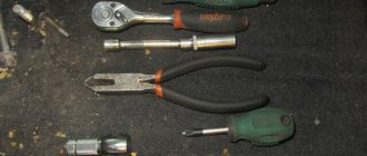
Auto mechanics recommend getting to the inner plane of the VAZ 2107 spar. To do this, you will need the following tools: keys, welding, grinder, screwdriver, pencil, ruler. You can approach the mechanism from the side of the mudguard. First, the front left wheel is dismantled by unscrewing the lower bolt securing the steering mechanism.
Further repairs involve drilling out several welding points. The exact quantity depends on the parameters of the window that is cut using a grinder. The amplifier is removed in the same way.
3 points appear around the hole and are drilled. With their help, the spacer sleeve of the amplifier is attached. Often this element no longer adheres to the inner wall of the VAZ 2107 side member, so it is removed along with the amplifier plate.
Now you can see the crack that has appeared on the amplifier itself. This defect can be eliminated by welding and installing a reinforcing lining. The same mounting bolt is used to install the spacer sleeve. In this case, the nut is screwed on from the side of the steering mechanism, which is in its place (it should not interfere with repair work on the VAZ spar). The bushing is welded with 3 points. After removing the bolt, the window is welded using the same pads. All welding points are treated with special anti-corrosion materials.
The final stage is the installation of the lower bolt for fixing the steering mechanism and installation of the wheel. It is easier to repair the spar at the initial stage of problems, since you will need to cut the window to a minimum size and unscrew only 1 bolt.
Types
As already mentioned, side members occupy different positions in the car. Here, a lot depends on the characteristics of the body (truck, passenger car or truck).
The location is as follows:
- Parallel and horizontal to each other;
- Vertical, with a slight bend;
- Horizontal and minimum angle;
- Horizontal and slight bend.
The type of design that is mentioned first has found application in freight transport.
Mercedes-Benz truck frame with parallel-horizontal side members.
As for the other options, they are popular and used in passenger cars.
Rear left floor member of VAZ 21099.
Installation of the power element and adjustment
The front suspension beam of the VAZ 2107 is mounted in the reverse order of its removal and in compliance with the rules and safety measures. A qualified replacement of this power element involves the use of new fasteners. During the work, it is necessary to defecate the suspension units, especially the ball joints and silent blocks. Replacing faulty elements will avoid repeated repairs in the near future.
Repair and restoration work of this kind on a VAZ 2107 car is usually carried out by the owners themselves. This is usually done in order to save money, but precise adjustment of wheel alignment angles is quite difficult to perform without special equipment. To do this, contact a specialized service station. Replacing load-bearing body elements inevitably leads to changes in settings.
Installing a new beam on a VAZ 2107 car will eliminate the problem of yaw while driving. The car becomes more controllable and does not deviate from the chosen trajectory. The new beam increases the torsional rigidity of the body, which has a positive effect on its overall condition.