Design and principle of operation
The designers of the Chevrolet Niva used a dual fan unit in the cooling system. This slightly complicated the connection diagram, but sharply increased the efficiency of radiator airflow. The fans are driven by 12-volt DC synchronous motors with a permanent magnet inductor. Electric motors have a closed, non-demountable design and do not require maintenance.
The power of each electric motor is 110 W. The fan assembly draws 18 amps.
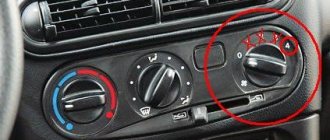
The fans are turned on one by one using an electromagnetic relay controlled by the on-board computer. When the coolant heats up above 99 degrees, the electric fan located closer to the engine air intake starts. The switch-on temperature of the second impeller is 101 degrees. The fan connection diagram is shown below.
The fan power system includes three relays and a resistor, which, if necessary, provides a reduced rotation speed of the first motor. Power is supplied from the battery through fuses that save the wiring and battery in the event of a short circuit. Control signals come from pins 29 and 68 of the motor controller.
The fans automatically turn off when the antifreeze cools to 95 degrees.
Consecutive switching on and off of engines reduces the load on the on-board electrical network. In most cases, it is possible to normalize the temperature only with the help of the first fan. This is especially useful when driving at night, when headlights and side lights put a lot of stress on the generator.
The ability to force fans on can be useful when driving off-road or in city traffic jams. However, the designers of the Chevrolet Niva did not provide the car with this function. It can be implemented independently or at a service station. It is necessary to connect backup relays parallel to the switching contacts and power them from a button installed in the car interior.
Useful video about installing and connecting the forced fan button on the Shnivy:
Important: forced activation increases the reliability of the cooling system. In case of malfunctions of sensors, relays or on-board computer, the driver can manually turn on the radiator airflow.
It is useful to equip the Chevrolet Niva with a switch that forcibly turns off the fan motors. This will protect their blades when fording water obstacles.
Cooling system 2123 Chevy-Niva Niva-Chevrolet
Purpose and classification of cooling systems
The temperature of the gases in the cylinders of a running engine reaches 1800-2000 degrees. Only part of the heat released in this case is converted into useful work. The remainder is discharged into the environment by the cooling system, lubrication system and external surfaces of the engine.
An excessive increase in engine temperature leads to burnout of the lubricant, disruption of normal clearances between its parts, which results in a sharp increase in their wear. There is a danger of sticking and jamming. Engine overheating causes a decrease in the cylinder filling ratio, and in gasoline engines it also causes detonation combustion of the working mixture.
A large decrease in the temperature of a running engine is also undesirable. In an overcooled engine, power is reduced due to heat loss; the viscosity of the lubricant increases, which increases friction; part of the combustible mixture condenses, washing away the lubricant from the cylinder walls, thereby increasing wear of parts. As a result of the formation of sulfur and sulfur compounds, the cylinder walls are subject to corrosion.
The cooling system is designed to maintain the most favorable thermal conditions. Cooling systems are divided into air and liquid. Airborne ones are extremely rare on cars these days. Liquid cooling systems can be open or closed. Open systems are systems that communicate with the environment through a steam pipe. Closed systems are isolated from the environment, and therefore the coolant pressure in them is higher. As you know, the higher the pressure, the higher the boiling point of the liquid. Therefore, closed systems allow the coolant to be heated to higher temperatures (up to 110-120 degrees).
According to the method of fluid circulation, cooling systems can be:
- forced, in which circulation is provided by a pump located on the engine;
- thermosyphon, in which fluid circulation occurs due to the difference in the density of the fluid heated by the engine parts and cooled in the radiator. While the engine is running, the liquid in the cooling jacket heats up and rises to its upper part, from where it enters the upper radiator tank through a pipe. In the radiator, the liquid gives off heat to the air, its density increases, it falls down and returns to the cooling system through the lower tank.
- combined, in which the most heated parts (cylinder heads) are cooled forcibly, and the cylinder blocks are cooled according to the thermosiphon principle.
Cooling system design
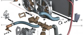
The most widespread in automotive internal combustion engines are closed liquid systems with forced circulation of coolant (coolant). Such systems include: a cooling jacket for the block and cylinder head, a radiator, a coolant pump, a fan, a thermostat, pipes, hoses, and an expansion tank. The cooling system also includes a heater radiator.
The coolant located in the cooling jacket, heated by the heat generated in the engine cylinder, enters the radiator, is cooled in it and returns to the cooling jacket. Forced circulation of liquid in the system is provided by a pump, and its enhanced cooling is due to intensive air blowing of the radiator. The degree of cooling is regulated by a thermostat and by automatically turning the fan on or off. Liquid is poured into the cooling system through the radiator neck or expansion tank. The capacity of the cooling system of a passenger car, depending on the engine size, is from 6 to 12 liters. The coolant is drained through plugs, usually located in the cylinder block and lower radiator tank.
The radiator releases heat from the coolant to the air. It consists of a core, upper and lower tanks and fastening parts. For the manufacture of radiators, copper, aluminum and alloys based on them are used. Depending on the core design, radiators are tubular, plate and honeycomb. Tubular radiators are the most widespread. The core of such radiators consists of vertical tubes of oval or round cross-section, passing through a series of thin horizontal plates and soldered to the upper and lower radiator tanks. The presence of plates improves heat transfer and increases the rigidity of the radiator. Tubes of oval (flat) cross-section are preferable to round ones, since their cooling surface is larger; In addition, if the coolant freezes in the radiator, the flat tubes do not rupture, but only change the cross-sectional shape.
In plate radiators, the core is designed so that the coolant circulates in the space formed by each pair of plates welded together at the edges. The upper and lower ends of the plates are also soldered into the holes of the upper and lower radiator tanks. The air cooling the radiator is sucked by a fan through the passages between the soldered plates. To increase the cooling surface, the plates are usually wavy. Plate radiators have a larger cooling surface than tubular ones, but due to a number of disadvantages (quick contamination, a large number of soldered seams, the need for more careful maintenance) they are used less frequently.
In the core of the honeycomb radiator, air passes through horizontal, circular tubes, washed externally by coolant. To make it possible to solder the ends of the tubes, their edges are flared so that in cross-section they have the shape of a regular hexagon. The advantage of cellular radiators is that they have a larger cooling surface than other types of radiators.
A filler neck, closed with a plug, and a pipe for connecting a flexible hose that supplies coolant to the radiator are soldered into the upper tank. On the side of the filler neck there is a hole for a steam pipe. The outlet flexible hose is soldered into the lower tank. The hoses are attached to the pipes with clamps. This connection allows for relative movement of the engine and radiator. The neck is hermetically sealed with a plug, isolating the cooling system from the environment. It consists of a housing, a steam (outlet) valve, an air (intake) valve and a locking spring. If the liquid boils in the cooling system, the vapor pressure in the radiator increases. When a certain value is exceeded, the steam valve opens and steam escapes through the steam pipe. After stopping the engine, the liquid cools, the steam condenses and a vacuum is created in the cooling system. There is a danger of squeezing the radiator tubes. To prevent this phenomenon, an air valve is used, which, when opened, allows air into the radiator.
To compensate for changes in the volume of coolant due to changes in temperature, an expansion tank . Some radiators do not have a filler neck, and the system is filled with coolant through an expansion tank. In this case, the steam and air valves are located in its plug. Marks on the expansion tank allow you to monitor the coolant level in the cooling system. Checking the level is carried out on a cold engine.
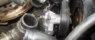
The coolant pump ensures its forced circulation in the cooling system. The centrifugal pump is installed in the front part of the cylinder block and consists of a housing, a shaft with an impeller and an oil seal. The pump body and impeller are cast from magnesium and aluminum alloys, and the impeller is also made from plastic. The pump is driven by a belt from the engine crankshaft pulley. Under the action of the centrifugal force that occurs when the impeller rotates, coolant from the lower radiator tank enters the center of the pump housing and is thrown towards its outer walls. From the hole in the wall of the pump housing, the coolant enters the hole in the cooling jacket of the cylinder block. The leakage of coolant between the pump housing and the block is prevented by a gasket, and at the point where the shaft exits there is a seal.
To increase the air flow passing through the radiator core, a fan . It is mounted either on the same shaft with the coolant pump, or separately. It consists of an impeller with blades screwed to a hub. To improve air flow to the engine and radiator, a guide casing can be installed on the latter. The fan can be driven in several ways. The simplest is mechanical, when the fan is rigidly fixed on the same axis with the coolant pump. In this case, the fan is constantly on, which leads to unnecessary consumption of engine power. In addition, the fan operates even in non-optimal modes, for example, immediately after starting the engine. Therefore, in modern engines such a connection is not used, and the fan is connected to the drive through a coupling. The design of the coupling can be different - electromagnetic, frictional, hydraulic, viscous (viscous coupling), but they all ensure that the fan automatically turns on when a certain coolant temperature is reached. This inclusion is provided by a temperature sensor. Moreover, the use of a fluid coupling and a viscous coupling makes it possible not only to automatically turn the fan on and off, but also to smoothly change its rotation speed depending on the temperature.
The fan can be driven not by the engine crankshaft, but by a separate electric motor. This connection is used most often, as it allows for quite simple automatic control of the on and off moments using a thermistor sensor (its electrical resistance changes depending on the heating). If the operation of the cooling system is controlled by the engine controller, then it becomes possible to change the rotation speed. In addition, the fan “reacts” to driving modes. For example, it turns on at idle when driving in traffic jams to prevent overheating and turns off during suburban driving at high speed, when natural airflow to the radiator is sufficient to cool it.
During engine startup, to reduce wear, it is necessary to quickly warm it up to operating temperature and maintain this temperature during further operation. A thermostat is used to speed up engine warm-up and maintain optimal temperature . The thermostat is installed in the cooling jacket of the cylinder head along the path of fluid circulation from the jacket to the upper radiator tank. Cooling systems use thermostats with liquid and solid fillers.
The liquid filled thermostat consists of a body, a corrugated brass cylinder, a stem and a double valve. A liquid is poured inside a corrugated brass cylinder, the boiling point of which is 70-75 degrees. When the engine is not warmed up, the thermostat valve is closed and circulation occurs in a small circle: coolant pump - cooling jacket - thermostat - pump.
When the coolant is heated to 70-75 degrees in the corrugated cylinder of the thermostat, the liquid begins to evaporate, the pressure rises, the cylinder, unclenching, moves the rod and, lifting the valve, opens the way for liquid through the radiator. When the temperature of the liquid in the cooling system is 90 degrees, the thermostat valve opens completely, at the same time, with a beveled edge, it closes the liquid outlet into a small circle, and circulation occurs in a large circle: pump - cooling jacket - thermostat - upper radiator tank - core - lower radiator tank - pump.
A thermostat with a solid filler consists of a housing, inside of which a copper cylinder is placed, filled with a mass consisting of copper powder mixed with ceresin. The container is closed on top with a lid. Between the cylinder and the cap there is a diaphragm, on top of which there is a rod that acts on the valve. In an unheated engine, the mass in the cylinder is in a solid state, and the thermostat valve is closed under the action of a spring. When the engine warms up, the mass in the cylinder begins to melt, its volume increases and it presses on the diaphragm and rod, opening the valve.
The coolant temperature is monitored using the temperature gauge and the engine overheat warning light on the instrument panel. The warning lamp and indicator are controlled by sensors screwed into the upper radiator tank and into the cylinder head cooling jacket.
Water (in outdated engine designs) or antifreeze can be used as a coolant. The quality of the coolant used for the engine cooling system is no less important for the durability and reliability of its operation than the quality of fuel and lubricants.
Antifreezes are coolants for the car cooling system that do not freeze at subzero temperatures. Even if the ambient temperature is below the minimum operating temperature of antifreeze, it will not turn into ice, but into a loose mass. With a further decrease in temperature, this mass will harden without increasing in volume and without damaging the engine. The basis of antifreeze is an aqueous solution of ethylene glycol or propylene glycol. Propylene glycol base is used less frequently. Its main difference is that it is harmless to humans and the environment, but also a higher price for the same consumer qualities. Ethylene glycol is aggressive to engine materials, so additives are added to it. There can be up to one and a half dozen of them - anti-corrosion, anti-foaming, stabilizing. It is the set of additives that determines the quality and scope of antifreeze. Based on the type of additives, all antifreezes are divided into three large groups: inorganic, organic and hybrid.
Inorganic (or silicate) are the most “ancient” liquids in which silicates, phosphates, borates, nitrites, amines, nitrates and their combinations are used as corrosion inhibitors. Antifreeze, which is widely used in our country, also belongs to this group of antifreezes (although many mistakenly consider it a special type of coolant). Their main disadvantage is their short service life due to the rapid destruction of additives. Deteriorated additive components form deposits in the cooling system, impairing heat transfer. The formation of silicate gels (clumps) in the coolant is also possible.
The most modern organic (or carboxylate) antifreezes use additives based on salts of carboxylic acids. Such antifreezes, firstly, form a much thinner protective film on the surfaces of the cooling system, and secondly, inhibitors act only in places where corrosion occurs. Consequently, additives are consumed much more slowly, thereby significantly increasing the service life of antifreeze.
Hybrid antifreezes occupy an intermediate position between organic and inorganic antifreezes. Their additive package mainly includes carboxylic acid salts, but also a small proportion of silicates or phosphates.
Antifreezes are available either in the form of concentrates or in the form of ready-to-use liquids. The concentrate must be diluted with distilled water before use. The proportion is determined by the required minimum freezing temperature of the antifreeze. The base of antifreeze is colorless, so manufacturers paint them in different colors using dyes. This is done to make it easier to control the level of antifreeze and warn about the toxicity of liquids. Color matching does not always indicate antifreeze compatibility.
In modern engines, the engine cooling system can be used to cool exhaust gas recirculation (EGR), cool automatic transmission oil, and cool the turbocharger. Some direct injection and turbocharged engines have a dual-circuit cooling system. One circuit is designed to cool the cylinder head, the other - the cylinder block. In the circuit cooling the cylinder head, the temperature is maintained 15-20 degrees lower. This makes it possible to improve the filling of the combustion chambers and the mixture formation process, as well as reduce the risk of detonation. The fluid circulation in each circuit is controlled by a separate thermostat.
Main elements of the Niva-Chevrolet cooling system (2123)
The cooling system of our car was based on the system from the pre-built “2121”, modifying its weak points, namely, we connected the radiator of the “stove” without a tap, diverted the coolant outflow from the stove not into the pump but into the thermostat, and the system also drains into the thermostat heating the dampers.
The main difference from the 2121 cooling system is the “cunning” thermostat, modified according to the type of article from the “behind the wheel” magazine.
and so, the “Classic” thermostat
And the principle of its operation:
Our thermostat (2123)
And the purpose of its pipes
As you can see, the principle of operation of the thermostat is not very different from the thermostat 2101, but significant changes have been made to it in terms of the control plan. Now the operation of the thermostat is also influenced by a decrease in temperature in the heater radiator and a decrease in temperature in the air damper heating circuit. When warming up, the thermostat passes hot coolant through the upper radiator hose. There is also a steam outlet pipe (4) that connects the cooling system with the expansion tank, where the pressure-regulating plug in the system is installed.
Basic cooling system malfunctions
External signs of cooling system malfunctions include overheating or undercooling of the engine. Engine overheating is possible as a result of the following reasons: insufficient amount of coolant, weak tension or broken coolant pump belt, failure to engage the clutch or fan motor, thermostat sticking in the closed position, large amounts of scale deposits, severe contamination of the outer surface of the radiator, malfunction of the exhaust (steam) plug valve radiator or expansion tank, coolant pump malfunction.
Sticking the thermostat in the closed position stops fluid flowing through the radiator. In this case, the engine overheats, but the radiator remains cold. An insufficient amount of coolant may occur if it leaks or boils over. If the coolant level has dropped as a result of boiling, you should add distilled water; if the liquid has leaked out, add antifreeze. You can open the radiator cap or expansion tank only when the coolant has cooled down sufficiently (10-15 minutes after stopping the engine). Otherwise, the pressurized coolant may splash out and cause burns. Liquid leakage occurs through leaks in the connections of the pipes, cracks in the radiator, expansion tank and cooling jacket, if the coolant pump seal is damaged, the radiator cap is damaged, or the cylinder head gasket is damaged. When operating a car, it is necessary to monitor not only the level, but also the condition of antifreeze. If its color becomes reddish-brown, it means that the system parts are already corroding. Such antifreeze must be replaced immediately.
Engine overcooling can occur due to the thermostat sticking in the open position, as well as in the absence of insulating covers in the winter. If the closed cooling system is leaking, then increased pressure is not created in it and the engine does not warm up to operating temperature. And since the engine does not warm up, the ECU constantly enriches the mixture. Thus, a leaky cooling system increases fuel consumption. Systematic operation of the engine on a rich mixture leads to oil dilution, increased carbon formation, and rapid failure of the catalytic converter.
It is also worth paying attention to the fact that coolant boils on average at 100C. The temperature for turning on the fans on the Niva-Chevrolet is 98-105 degrees. The expansion tank plug creates a pressure of 1 atm in the system, which increases the boiling point of the liquid to 110 C (approximately). IF THE COOLING SYSTEM IS DEPRESENTED, THEN THE COOLANT BOILES AT 100C AND THE ENGINE IS OVERHEATED. It is very important that the pressure in the system is exactly 1 Atm, which can only be ensured by a good expansion tank cap. If the pressure is higher, the rubber pipes will leak, and sometimes the radiators will diverge where the tanks are attached.
Circuit breakers
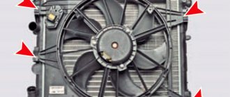
The electrical circuits of Niva Chevrolet cars produced before and after 2009 are different. In both cases, 50-amp fuses protecting the electric fan power circuits are located in an additional unit. It is located behind the glove box on the passenger side of the cabin. The figure shows where the fan fuses are located.
If the permissible current is exceeded, the insert melts and the circuit opens. Therefore, fuses are the first thing to check if the electric cooling fan does not work. The performance of a part can be assessed visually or using an ohmmeter (multimeter). To do this, you will first have to remove the fuse from the socket.
Fan relay
The additional block contains not only fuses. There are also three electromagnetic relays that control the operation of the electric motors of the cooling system. Their control circuits are powered from the ignition switch and on-board controller outputs, and the power current comes from the battery through fuses.
The relay operates as follows:
- Voltage is applied to the control terminals.
- Current passes through the inductor, resulting in an electromagnetic field.
- The steel contacts attract and close.
- The current passing through the relay drives the electric motor.
As soon as the control voltage disappears, the contacts open under the influence of the spring and the fan stops.
You can check the functionality of the relay in three ways:
- Replace the relay with a known working one and test the operation of the system.
- With the engine off and the ignition on, disconnect the temperature sensor connector. You should hear the relay click.
- Dismantle and test the output contacts with a multimeter, applying voltage to the terminals of the induction coil.
Possible malfunctions and their causes
1.Both fans do not work. The electric motors may fail, the temperature sensor may malfunction, or the power wires coming from the battery or ignition switch may be broken.
2. The second fan does not work. Causes: sensor malfunction, fuse or electromagnetic relay failure. It is also possible that the power cable may be broken.
3. The left fan does not turn on. Causes: faulty power resistor or temperature sensor, blown fuse or relay. It is also possible that the power cable may be broken.
4. Only two fans turn on at a time. This happens when an additional resistor in the circuit of the first electric motor breaks.
5. The fan does not turn off. Typically, the fan runs constantly when the relay is broken or the coolant temperature sensor is faulty.
Repair of fans, sensor, relays, fuses and additional resistor is not provided. If these parts break, they should be replaced with new ones.
Replacing fans
If the fan motors do not start when the wires from the battery are connected directly to the power terminals, the devices must be replaced.
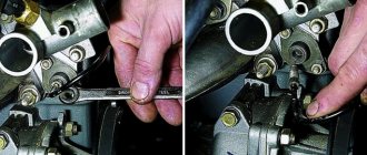
To do this, you will need a set of wrenches ranging in size from 10 to 17 mm and a Phillips screwdriver.
Before starting work, you need to drive the car onto an inspection ditch or a lift and turn off the power to the on-board network by removing the negative terminal of the battery.
Fans are dismantled as follows:
- Remove the crankcase protection and mud guard.
- Unscrew the screws and remove the thick spider-shaped plate and a couple of tin covers that are located in front under the bottom of the car.
- Unscrew the radiator frame cross member.
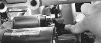
- Loosen the tension and remove the power steering belt and pump.
- Remove the 4 bolts holding the power steering pump.
Useful video showing how to remove and change fans:
Important: to get to the bolt covered by the oil filter, you need to move the amplifier away from the bracket.
- Push the pump back, hanging it on the hoses.
- Remove the air conditioner drive belt.
- Remove the bolt holding the timing belt pulley.
- Remove the pulley and belt.
- Unscrew the four nuts at the corners of the electric fan housing and the two bolts securing it in the middle.
- Remove the fan unit from the studs and pull it down.
Tip: The crankshaft position sensor makes it difficult to remove the fans. Therefore, they need to be pulled out gradually. The left side is lowered first, then the block is moved to the left, raising the right edge so that the casing becomes vertical.
This method is probably suitable for restyled Niva Chevrolet models. On older cars, you will have to remove the radiator grille and bumper, unscrew the fasteners and move the air conditioning and cooling radiators forward. After this, access to the electric fans will be open.
During dismantling, you should carefully remember the procedure. Assembly is carried out in reverse order.
Important: the service life of the fan motors is approximately the same. Therefore, even if one of them fails, both must be replaced. Otherwise, you will soon have to repair the car again.
Popular materials
Not available, for the year of manufacture either. The fans will turn on only based on the sensor signal. Tip: The crankshaft position sensor makes it difficult to remove the fans. Starter
From the chip connected to one of the fans, we remove the negative wire; it is usually black.
But in this case, in order to turn on the fans at high speeds, you will need to redo everything back.
The most popular are electric-driven fans, which consist of an electric motor, an electronic control unit, a temperature sensor and a fan switch relay.
Crankshaft position sensor. Except for the tee.
Let's look at the diagram Connecting Niva fans in a serial connection. Injection system fuse box.
We drag the harness over the steering column and move a piece of hose along it so that its middle is above the steering shaft. Distributor NIVA. Control of transfer case levers in all modes. Practice. Differentials NIVA 1h
More on the topic: Energy inspection of a building
Removing and replacing the fan resistor
Before starting work, you must go to the inspection hole and remove the terminal from the battery. For repairs you will need 10-13 wrenches, a screwdriver and a new resistor. The part is installed in the beam below the radiator. The removal procedure is as follows:
- Unscrew the fastening bolts and remove the crankcase protection along with the mudguard.
- Remove the protective strip of the resistor and unscrew the part.
Assembly is performed in reverse order.
Source
Checking and removing fans
To understand whether they work or not, you need to disconnect the connector from their motors, and connect a lamp to the wires through which voltage is supplied; we do the same with the sensor; if both lamps light up, then the problem is in the fans.
To remove them you need to do the following:
- Disconnect all wires
- Removing the upper pipe
- Removing the bumper
- If there is an air conditioner, bend the tubes (this must be done carefully, as they may burst) or drain the freon (filling it back will not be cheap), then remove the air conditioner radiator.
- You need to loosen the nuts on the radiator casing
- Tilt the radiator so that you can remove the fan unit
- Unscrew the bolts that secure the block and remove it
After removal, it is recommended to immediately replace both with new ones, since there is a possibility that a little time will pass and the second element will fail and all replacement work will need to be done again. You can do this procedure from below, but you will need special equipment, and you will need to move the engine ten centimeters back, which is very labor-intensive.
Operating principle and system design
Niva design engineers used a paired block of coolers to increase the efficiency of radiator air conditioning , although this made the connection diagram more difficult to maintain in the future.
A 12-volt permanent magnet synchronous motor (PMSM) is used to drive the fans. Thanks to their non-separable design, electric motors do not require special maintenance. The power of the electric motor is 110 W, and the ventilation unit itself, when fully assembled, uses 18 A.
Switching on occurs in a certain order thanks to an electromagnetic relay controlled by the on-board computer. The electric fan, located next to the radiator grille, starts when the temperature of the cooling fluid exceeds 99°C. The second impeller turns on when the permissible heating values reach 101°C.
Operation of fuses
The configurations of the 2009 Chevrolet NIVA and later models differ quite greatly in their electrical supply circuits . However, in both cases, the fuses are provided with special inserts designed to protect the power circuit and located in the additional unit located behind the glove compartment. The electric current in the circuit is 50 A.
If the digital current values are exceeded, the circuit may open or melt . The performance of a part is assessed using a visual component and a multimeter. To evaluate, you should carefully remove the fuse located in the block in advance.
Relay for starting the fan
The spare block may contain not only the fuses themselves, but also electromagnetic relays . They control the operation of the engine cooling system, the circuits of which are powered by the ignition switch of the on-board computer. The current comes from the battery through the fuses themselves.
The relay operates as follows : at the very beginning, voltage is applied to the output, as a result an electromagnetic field is formed by passing current through the inductive coil. Subsequently, the current passing through the relay starts the engine. If the voltage is removed, the contacts will open due to the spring that is present in the mechanism, and the fan itself will stop.
There are several ways to check the operation of the relay . The simplest method is to replace the relay with the same working one and check the condition of the system. Turn off the engine, then disconnect the temperature sensor connector, after which you will hear a characteristic click of the relay. Then you need to remove and test the output contacts using multimeters, constantly applying voltage to the output. From the temperature sensor, information is supplied to the unit switching device.
The temperature sensor itself is a resistor, the values of which vary in a variable temperature range : from 1.3-1.8 Ohms at 30°C to 155-196 Ohms at 90°C. To give an accurate assessment of its performance, use a thermometer and an ohmmeter, calculating the resistance at different temperatures. To check, the part is removed and then immersed in an aqueous environment. The sensor can be found near the main exhaust system. It is dismantled using a spanner.
Power sensor
The control unit receives information about the antifreeze temperature from a temperature sensor. It is a resistor whose resistance changes with heating and cooling: from 1.3-1.8 kOhm at 30℃ to 155-196 Ohm at 90℃. You can check its performance using an ohmmeter and a thermometer. To do this, you need to remove the part, immerse it in water and measure the resistance at different temperatures.
The sensor is located on the engine head in the area of the exhaust pipe of the cooling system. You can unscrew it with a socket or socket wrench.
We recommend watching a video that shows where the sensor is located and how to check:
Typical breakdowns
The most common reasons : malfunction of the temperature sensor, damage to the power system, malfunction of the wires passing from the battery to the ignition switch, inoperability of the second fan.
The main reasons may be sensor defect , failure of a fuse or electromagnetic relay. If the performance of the left fan is reduced, this may indicate a breakdown of the “resistance”, temperature sensor, damage to the fuse or relay.
When turning on two fans simultaneously, you should pay special attention to one more device in the circuit of the first electric motor. Failure to operate occurs when the relay itself is damaged or the temperature receiver for cooling the liquid is damaged.
All of the above parts are not repaired . After each damage they are replaced with new ones.
Tips for motorists
In the cold season, such a malfunction can be noticed when moving at low speed and stopping frequently. In summer it will appear much faster. For the engines of this car, the use of two fans in the cooling system is provided, since the car was originally designed for driving in difficult road conditions. The reason the fan fails to turn on may be a small “problem” that will only take a couple of minutes to fix.
Where to start the search
Since the fan is driven by an electric motor, a car tester is needed to troubleshoot; in extreme cases, a test light will do. It is small in size, so you can carry it in your car all the time. The electric motors are switched on through the contacts of electromagnetic relays, of which there are three in the cooling system on this car. Pulses to turn on the fans come from two temperature sensors. There are two of them in the system, and they are installed on the engine.
Electrical circuit diagram of Chevrolet Niva cooling system fans.
Electrical circuit diagram of Chevrolet Niva cooling system fans.
Cooling system fans.
The fans can only be turned on when the engine is running. Depending on the engine temperature, the controller turns on the electric motors of the engine cooling system fans through auxiliary relays, individually or in pairs.
The electric cooling fans turn on if the coolant temperature exceeds 105 °C .
The electric fans turn off when the coolant temperature drops below 101 °C or the engine stops.
The electric fans turn on regardless of the coolant temperature when the air conditioning compressor is turned on.
If there are active coolant temperature sensor fault codes, the cooling system fans operate until the codes clear or the engine stops.
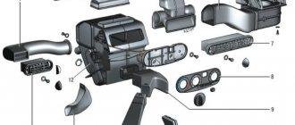
Cooling system fans electrical circuit diagram.
1 – right electric motor of the engine cooling system fan; 2 – additional relay; 3 – fuse; 4 – additional resistor; 5 – relay for turning on the right electric motor; 6 – left electric motor of the engine cooling system fan; 7 – relay for turning on the left electric motor; A – to the battery terminal; B – to the main relay; C – to the “+” terminal of the battery.
Wire color designation.
Source
Relay and fuse diagram for Chevrolet Niva after 2009 (restyling)
Year of release
| 2009 | 2010 | 2011 | 2012 | 2013 | 2014 | 2015 | 2016 | 2017 | 2018 | 2019 and present |
Relay circuit
| Number on the diagram | What is he responsible for? |
| K1 | not used |
| K2 | windshield wiper relay |
| K3 | relay-interrupter for direction indicators and hazard warning lights |
| K4 | low beam headlight relay |
| K5 | headlight high beam relay |
| K6 | additional relay |
| K7 | Rear window defroster relay |
| K8 | reserve |
Fuses and inserts
| Number | What is he responsible for? | Current strength, A |
| F1 | License plate lights, side light lamps in the left headlight and left rear light, engine compartment lamp, side light indicator lamp | 5 |
| F2 | Low beam lamp left headlight) | 7,5 |
| F3 | High beam lamp, left headlight unit), indicator lamp for turning on the high beam headlights | 10 |
| F4 | Left fog lamp | 10 |
| F5 | Power window relay, front power windows | 30 |
| F6 | Cigarette lighter fuse | 15 |
| F7 | Horn Relay, Horn, Trunk Lamp | 20 |
| F8 | Heated tailgate glass element, heated tailgate glass relay, heated outside rear view mirror elements | 25 |
| F9 | Heated tailgate switch, windshield wiper relay, windshield wiper motor, windshield washer pump, right steering column switch, glove compartment lamp, reverse lamps | 20 |
| F10 | Remote control unit for electrical accessories (door lock) | 20 |
| F11 | Side light lamps in the right headlight and right rear lamp, instrument lighting brightness control | 5 |
| F12 | Low beam lamp, right headlight), gear motors for headlight beam control | 7,5 |
| F13 | High beam lamp, right headlight) | 10 |
| F14 | Right fog lamp | 10 |
| F15 | Outside mirror control unit, electric outside rear view mirrors, heated seat control unit | 20 |
| F16 | Relay-breaker for direction indicators and hazard warning lights | 10 |
| F17 | Interior lamps, anti-theft system status warning lamp, brake lights, additional brake light | 7,5 |
| F18 | Heater fan, heater fuse | 25 |
| F19 | Relay-interrupter for direction indicators and hazard warning lights (in turn signal mode), instrument cluster (except for engine management system malfunction warning lamp), starter relay | 10 |
| F20 | Fog lamps in the rear lights, anti-theft control unit, buzzer | 7,5 |
Remote relays
| Number | What is he responsible for? |
| 1 | Fog lamp relay (FTL) |
| 2 | Power window relay |
| 3 | Seat heating relay |
| 4 | Horn relay |
| 5 | Starter relay |
Chevrolet Niva cooling system fan connection diagram
Sometimes an opportunity happens - the temperature gauge on the dashboard of your Niva Chevrolet is already in the red zone, and the cooling fan doesn’t even think of turning on to somehow influence the situation. There are several reasons for this - starting from the failure of the relay or coolant temperature sensor and ending with the failure of the fan itself. In order not to panic and not think about global and expensive repairs, you need to accurately determine the cause of this breakdown. For this we need a wiring diagram for the electric fans of the cooling system, by the way, here it is:
As you can see in the diagram, we have two fans, and three relays. Where are these relays located and which one is responsible for which fan? This photo will answer your question:
Actually, now all that remains is to check the arrival of +12 volts to certain circuits according to the diagram and find the culprit of the non-working cooling fan, which is much more difficult to do without a diagram at hand!
By the way, here is another visual diagram of their inclusion:
By the way, some who are not indifferent to the sounds of cooling fans are finalizing their connection diagram, but that’s a completely different story.
Source
Reasons why the cooling fan does not work on a Chevrolet Niva
To maintain the optimal temperature in the engine, a cooling system is installed in the car. One of the main elements in this system are fans, thanks to which the required amount of air is supplied to the engine through the radiator core. If it stops working, the Niva Chevrolet cooling fan overheats as excess heat begins to accumulate. Unlike classic cars, it has two fans, making the functioning of the systems much more complicated. If the arrow that shows the temperature is in the red area, and the cooling system refuses to work, and at the same time the cooling fan does not turn on, then the car should be taken to a car service center as quickly as possible, or you should try to find the cause of the malfunction yourself.