Den242 › Blog › Identifying faults in the ignition system
Determining malfunctions in the ignition system
Malfunctions in the ignition system lead to the fact that either the engine does not start, or runs intermittently at idle or in all modes, or does not develop full power.
Due to the fault of the ignition system, the engine may not start for the following reasons:
open or short circuit in the low voltage circuit;
malfunction of spark plugs, distributor, coil or ignition switch;
incorrect connection of wires to spark plugs;
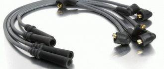
contamination or breakage of high-voltage wires;
incorrect setting of ignition timing;
damage to the runner and distributor cap.
Unstable engine idling may be caused by an increased gap between the spark plug electrodes or incorrect ignition timing. The reasons why the engine operates unstably in all modes may be damage or unreliable connection of high-voltage wires, oily or faulty spark plugs, faulty switch, slider or distributor cap.
The reason why the engine runs unstably at high speeds may be a faulty ignition distributor.
The engine does not develop full power due to a faulty ignition switch or distributor or incorrect ignition timing.
When the ignition switch operates, a large amount of heat is generated.
In order not to damage the electronic devices of the ignition system, as well as to avoid possible injuries, follow these rules:
1. Do not touch high-voltage wires and system components (coil, switch, etc.) with your hands while the engine is running, since the non-contact ignition system has a higher voltage compared to the contact system.
2. Do not check the operation of the system “for a spark” by holding the tip of a spark plug or a high-voltage wire in your hands. To check, use a special spark gap.
3. It is prohibited to lay low and high voltage wires of the ignition system in the same harness.
4. Do not disconnect the wires from the battery terminals with the ignition on: this will damage the electronic components of the ignition system.
5. It is forbidden to disconnect the block with wires from the switch when the ignition is on: the switch will be damaged.
6. Do not loosen the screws that secure the switch: through these screws it is connected to ground.
During the check, do not touch the wires and devices of the ignition system while the engine is running.
Disconnect and connect the ignition system wires only when the ignition is turned off.
To check for a “spark” you need to use a special spark gap with a gap between the electrodes of 5–7 mm. If the gap is more than 10 mm, the electronic devices of the ignition system may fail. You can use old working spark plugs as a spark gap. The gap between the spark plug electrodes should be 0.7–0.8 mm.
Malfunctions in the ignition system lead to unstable engine operation, and starting problems are also possible.
Before you start troubleshooting the ignition system, make sure that the fuel system is working properly. If gasoline does not enter the carburetor, the engine will not start. To check, remove the hose from the carburetor coming from the fuel pump and pump fuel with the manual pumping lever, while fuel should splash out of the hose. The engine may run rough due to a high fuel level in the carburetor float chamber, a faulty brake booster vacuum, or a leaky connection between the booster vacuum hose and the engine intake pipe or the booster check valve.
3.10.1. Reasons for unstable engine operation:
1. Dirty or damaged high-voltage wires. This is especially true in wet, rainy weather.
2. High-voltage wires are not fully inserted into the sockets of the ignition distributor cap or ignition coil, as well as into the tips of the spark plugs.
3. The spark plugs are faulty or the gaps between the spark plug electrodes are not adjusted.
4. The ignition timing is incorrectly adjusted.
5. Malfunction of the slider or its resistor.
6. Damage to the ignition distributor cap (especially noticeable in damp and rainy weather).
7. Malfunction of the ignition switch.
8. Malfunction of the ignition coil.
Periodically clean high-voltage wires, spark plug tips, ignition coil, distributor cap and switch with base from dust and dirt.
3.10.2. Engine won't start
1. Check if voltage is supplied to the spark plugs. To do this, remove the high-voltage wire from the central socket of the distributor cover and connect it to the arrester. Turn on the starter for a few seconds, while a spark should periodically jump between the electrodes of the spark gap. If there is no spark, then voltage is not supplied to the spark plugs. If there is a spark, check the operation of the spark plugs in the same way, removing the tips with wires from them one by one. If any spark plug does not spark, replace its wire. If there is a spark on all wires, but the engine does not start, replace the spark plugs.
2. If voltage is not supplied to the spark plugs (no spark on all four spark plugs), replace the distributor slider. Sometimes the slider resistor fails. You can check its performance using an ohmmeter: the resistor resistance should be 0.9–1.1 kOhm. If the resistance is different from the specified value, replace the slider. If, after replacing the slider, voltage is not supplied to the spark plugs, replace the ignition distributor cap. If after this the engine does not start, replace the ignition coil, switch and ignition distributor in sequence.
3.10.3. The engine is running erratically
1. Clean the high-voltage wires and check their condition. Damage to the insulation of high-voltage wires and the ignition distributor cap can be detected in the dark. To do this, start the engine and inspect the engine compartment. A characteristic glow will be visible in the damaged area.
2. To determine which spark plug is faulty, disconnect the wire from it with the engine off, and then start the engine. If interruptions in engine operation increase, then the spark plug is working. After this, stop the engine and connect the wire to the spark plug. Remove the wire from the other spark plug and start the engine again. If the nature of the vibrations has not changed, this spark plug is faulty and must be replaced. If the engine continues to run rough, replace the spark plug wire.
3. If all spark plugs and wires are in good condition, and the engine continues to run unstably, replace the slider and ignition distributor cap.
4. If, after replacing the cover and slider, interruptions in engine operation continue, replace the ignition switch.
Purpose, principle of operation of the ignition coil
The device is the most conservative part in a gasoline internal combustion engine. Its prototype was invented in Germany by the engineer Ruhmkorff in the mid-nineteenth century. It replaced magnetos in automobile engines in the early 20th century.
The main purpose of the device is to convert low-voltage electrical pulses with an amplitude of about 12 Volts (vehicle on-board voltage) into high-voltage pulses with an amplitude of more than 15,000 Volts. High voltage is necessary to break down the working area of the spark plug.
According to the type of design and ignition circuit, the coils are classified:
Ignition coil device
Single devices are used in systems with an ignition distributor. Twins are used in four-cylinder internal combustion engines without a distributor. One part forms a high-voltage pulse to the 1st and 4th cylinders, the second serves the 2nd and 3rd. Triple and quad coils are sometimes used in six-cylinder and eight-cylinder engines, respectively. Individual coils are widely used in modern cars. They are installed on each spark plug individually. A custom spark plug coil has a number of advantages over conventional ones:
By type of control they are divided into:
In the ignition contact bobbins, a low-voltage pulse is generated by a chopper. When the primary circuit is switched by a breaker, an electromotive force pulse is induced in the primary circuit. The device is an autotransformer that increases the pulse amplitude N times, where N is the transformation coefficient equal to the ratio of the number of turns in the secondary to the primary winding. The transformation ratio of contact devices exceeds 1000.
Contactless systems use electronic coils. Their transformation ratio is higher and they form a stable spark. During repairs, contact and non-contact devices cannot be interchanged.
A built-in switch is installed on most individual coils, often installed on dual coils. Their disadvantage is a higher probability of failure due to the presence of electronic components.
Signs of a faulty switch: how to check the switch yourself.
Purpose and design features of the switch.
A switch is one of the elements of a car's electrical equipment. His task
– ensuring normal operation of the contactless ignition system. The assembly is fastened in the engine compartment.
The device is different
reliability, ability to withstand severe vibrations and shock loads. This is very important, because the switch housing contains sensitive electronics.
At the heart of the VAZ switch
– standard L 497 microcircuit, which controls an “NPN” type transistor.
>Scheme feature
– possibility of programming by the user and setting the required delay coefficient. Starting a cold engine directly depends on the correctness of this indicator.
Thanks to precise settings
, you can speed up the crankshaft rotation speed (while eliminating failures in operation) and guarantee high-quality traction of the power unit.
The main parameters of the switch device include:
Voltage range – from 6 to 16 Volts; operating voltage level – 13.5 Volts; ensuring an uninterrupted spark when the crankshaft rotates in the range from 20 to 7000 rpm; switching current – from 7.5 to 8.5 A.
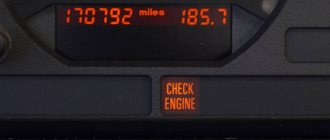
Signs of a faulty switch.
One of the main symptoms of a faulty switch is loss of spark.
. The engine starts hard and stalls from time to time, causing interruptions in operation.
But don't rush to replace it
- it is important to verify the reason, because
loss of spark can occur for a number of reasons
- failure of the Hall sensor, rupture of the timing belt, malfunction of the ignition coil, poor contact in the distributor cap, problems in the wiring, and so on.
If diagnostics of other nodes does not produce results
, then we can move on to our “hero”. But how to check the switch, since the device has a very complex design?
How to check the switch yourself.
Most car enthusiasts don’t bother with diagnostics and simply install a new unit. This method has its advantages.
Firstly
, there is no need to waste time checking - just install a new part.
Secondly
, you can immediately determine whether this is the reason or not. In fact, there is no need to be afraid of the work, because checking the switch takes a few minutes.
So, to carry out work at home, a test lamp (nominal voltage should be 12 Volts) and a standard set of keys are enough.
With their help, you can verify the presence or absence of pulses, and later make a decision about the serviceability of the device itself.
Algorithm for checking the switch:
To begin work, it is advisable to disconnect the battery so as not to accidentally short-circuit the wiring that you will unscrew.
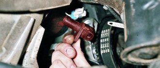
Using an eight-point wrench, unscrew the nut and remove the wiring from the ignition coil marked “K”. This wire is easy to recognize - it is brownish in color and goes to the terminal labeled one on the switch;
Connect this wire through a control light to terminal “K” on the ignition coil, and then connect the battery;
Turn on the engine starter and observe the lamp's actions. If it blinks, then the switch is working. If the light bulb does not show any signs of life, then the only way out is to replace the device.
If there are doubts about the serviceability of a part, the check should be carried out on a special stand (there is always one at the service station).
In this case, it is possible not only to determine whether the product is working, but also to measure the duration of the pulses.
When the first suspicions appear, you should not immediately change the switch or spend money on a specialist. You are quite capable of doing the job yourself.
Moreover, now you know how to check the switch on the VAZ 2109 and other models of the domestic brand. All that remains is to allocate time and prepare a minimum set of tools. Have a good trip and of course no breakdowns.
Source: autozona54.ru
Top 5 reasons for switch failure: overload and other reasons
Breakdown of switching equipment can be caused by external and internal factors.
Violation of basic operating rules
Trivial carelessness can lead to failure of the switch. The quality of work is affected by various mechanical influences:
- sudden pulling out of network cables;
- accidental blows to the body;
- falling from a great height.
Among the reasons for damage to internal components, it is also worth mentioning the fire of microcircuits as a result of contact with water or any other liquid.
To protect the switch from the human factor, it is enough to follow the rules of safe operation, described in detail in the user manual.
Low quality software
The problem of insufficiently reliable software is faced by owners of budget switches from unknown manufacturers, as well as users of counterfeit network equipment (counterfeits of well-known brands).
Important: Using the link https://www.moyo.ua/comp-and-periphery/network_equip/kommutatory-nastraiv/cisco/ you can purchase an original Cisco switch based on certified software.
If the software malfunctions, re-flashing the switch can restore functionality.
Electrical network instability
An electrical surge or short circuit is fatal to almost any network equipment. Switches, routers, access points and other devices are especially susceptible to damage during a thunderstorm.
To protect devices from short-circuit currents and sudden voltage drops, uninterruptible power supplies and external stabilizers should be used.
Damage to ports for connecting equipment
If the switch itself, according to visual signs, works without interruptions, but you cannot connect any device to it, the problem lies in the network ports. Most likely, as a result of prolonged use, the “inputs” simply wore out and became unusable.
This problem can be solved at any service center. Specialists will quickly replace damaged ports and restore functionality to the device.
Failure of one of the internal elements of the switch
If the switch stops turning on, you should look for the cause of the breakdown inside. The device’s memory board may have burned out, one of the microcircuits has failed, or the built-in power supply has stopped working.
A trip to the service center or independent replacement of faulty spare parts will help eliminate all these breakdowns.
Don’t panic and immediately after a switch malfunctions, look for a replacement. Most problems can be fixed with much less money spent on repairs than on purchasing a new device.
Checking and replacing the ignition switch VAZ 2107
The task of the VAZ 2107 ignition system is to generate a spark that ignites the air-fuel mixture in the cylinders. In older “classic” models, this works based on the “breaker-ignition coil” connection. On more modern cars, a contactless ignition system is installed, where the VAZ 2107 ignition switch is responsible for sparking.
Switch malfunctions affect the efficiency and performance of the entire ignition system and the vehicle as a whole. Therefore, it will not be superfluous to learn how to check the VAZ 2107 switch and replace it, if necessary.
What is it for, where is it located and what does it look like?
As was said, the switch is needed for driving on low-octane gasoline. This fuel costs much less than premium grades. At the same time, the engine output still remains at a high level due to better ignition of the air-fuel mixture. Thus, the switch is a device that promotes the appearance of a productive spark in the ignition unit. It can be considered a microcomputer stimulating the converter. Naturally, the switch must rely on some data. In our case, these are signals from the synchronization sensor.
Structurally, the element can be combined with the ECU. In this case, it is located on the distributor (VAZ 2106, 2107) or next to the converter - on the ZIL TK102U. The option of being on a separate metal platform is no exception. As a rule, this is either a car fender or a partition under the hood (Ford). And on German Audis the switch is installed in the engine compartment under the windshield. It is provided with a protective casing made of moisture-proof material.
Switch Purpose
The non-contact ignition system is distinguished by the fact that the electrical impulse supplied to the coil (coils) is generated not by the breaker contact installed in the distributor, but by the switch. The electronic circuit of the latter supplies a spark to the cylinders with an optimal timing, based on data about the current operating mode of the engine and the position of the crankshaft at each specific moment.
The switch is able to withstand physical stress, vibration and temperature changes over a wide range. The absence of contacts in the circuit ensures greater reliability and durability of the unit. Another advantage of this solution is that the VAZ 2107 switch has the ability to be reprogrammed by the user to set the timing advance corresponding to the fuel quality and dynamic requirements for the vehicle.
VAZ 2107 switch parameters
The operating voltage of the switch is 13.5 volts, the permissible voltage range is from 6 to 16 volts. The maximum switching current is 8.5 amperes. The switch provides stable sparking in the engine speed range from 20 to 7000 rpm.
Design and principle of operation
The first switches were extremely primitive. A simple circuit of transistors was regulated using an electrical impulse. The device did not last long in this form. The era of high technology has arrived, thanks to which more effective innovative solutions have begun to be applied.
On cars assembled in the Russian Federation, the spark stimulator was first used on the VAZ-2108 car. The device belonged to the 36.3734 series, also of native production. Subsequently, more modernized switches with different design and technical designs began to be used. However, combined or composite assembly technology has always remained unchanged for Russian microcircuits. And its advantage is that it is repairable, unlike the same foreign analogues.
Today, a switch is a combination of several elements: spark plugs, transistors, sensors. It can be used in hybrid or thyristor ignition. Electrical impulses are controlled automatically, which provides a number of practical advantages:
And when the Hall element was introduced, and the switch began to control several converters at once, the advantages only increased. So much so that they began to use a “coil + commutator” tandem on each individual spark plug. Here's what exactly we managed to achieve:
The principle of operation of the switch can be imagined as follows. First, the system monitors the position of the engine crankshaft. Then, an inductive Hall sensor included in the distributor design takes readings from the position of the pistons in the cylinders. It also supplies the switch with an impulse. The signal is amplified to 12 volts and sent to a coil. Due to this, the current decreases and the voltage increases.
Nowadays, electronic switches are used for efficient ignition of fuel in VAZ 2109, 2110, 2114 Samara, as well as ZAZ-1102. The 3734 series of these devices is produced under article numbers 3620-, 36- and 78. The tasks of the key here are performed by a productive mosfit, and the current value is controlled by an integrated electrical circuit.
Connection diagram for VAZ 2107 switch
The contactless ignition system of the VAZ 2107 includes:
- Candles.
- Ignition distributor (sensor).
- Anti-interference screen.
- Non-contact slider position sensor.
- Switch that controls spark generation.
- Ignition coil.
- Assembly block.
- Ignition switch relay.
- Ignition switch on the steering column.
Wire “A” goes to the positive terminal of the car generator output. The connection diagram for the VAZ 2107 switch is shown in the figure:
Signs of a malfunction of the VAZ 2107 switch
The main symptom of a switch failure is the absence of a spark at the spark plugs. Alternatively, the spark may not be powerful enough or disappear periodically. In this case, the engine starts poorly, runs intermittently, stalls at idle, loses power, or its speed constantly fluctuates. It should be remembered that all these signs can also appear due to malfunctions of other parts of the ignition system: the Hall sensor. wires and spark plugs, ignition coil, distributor. The spark also disappears when the timing belt breaks and there is no contact in the power supply circuit of the ignition system. To accurately determine the cause, it is necessary to separately check the functionality of the switch.
Price
More details in the table.
And finally, remember that when replacing a powerful switching transistor, it is important to pay attention to the quality of fixation of the part to the switch body. Many beginners make mistakes here or do not apply enough heat-conducting paste. As a result, the device cannot be repaired.
A characteristic feature of the car can be considered its rapid obsolescence, but long life. The most modern car today, in at least two years, will be inferior to other, newer cars with improved characteristics. But even now there are cars from the last century on the roads. Therefore, it is not just interesting, but sometimes necessary, to know at least in general terms what such vehicles are, their structure, features, including such a thing as a simple ignition switch, which significantly changed the capabilities of the car.
Examination
The easiest way to test a switch is to try replacing it with a known good one. But this can only be done if a working switch is at hand. It is not advisable to buy a new unit just to test the operation of the old one. There is a cheaper and not particularly complicated way. To test the switch, you only need a standard set of keys and a test lamp. This is enough to verify the presence or absence of pulses supplied to the ignition coil. Before checking the switch, make sure that “plus” is supplied to it and the ignition coil. Also check the connection contacts of the Hall sensor and the functionality of the sensor itself. Checking the VAZ 2107 ignition switch is performed as follows:
- turn off the ignition;
- unscrew the nut on the ignition coil and disconnect the brown wire marked “K” (the wire goes to connector “1” on the switch);
- connect a test lamp to the gap between the wire terminal and the coil terminal;
- turn on the ignition;
- turn the key and start the starter.
A flashing light indicates a working switch. If the lamp does not light, the switch needs to be replaced.
Replacing a VAZ 2107 switch
To replace the switch, you must complete the following steps:
- turn off the ignition;
- disconnect the wire block from the switch connector;
- unscrew the fastening nuts;
- remove the old switch and put a new one in its place;
- tighten the fastening nuts;
- connect the wire block to the connector.
At this point, the replacement of the VAZ 2107 switch is completed and you can check the operation of the ignition by trying to start the engine.
Source: semerkavaz.ru
Ignition settings
When setting up the ignition, you will need to do the most important thing - install the shafts according to the marks so that the gas distribution functions synchronously with the operation of the piston group. This is the first thing you should do before you start adjusting the ignition. It is worth noting that there should not be any particular difficulties during setup, especially on VAZ 2108-21099 cars. The thing is that the ignition distributor on the engines of these machines can only be installed in one position. Moreover, the ignition switch does not undergo any settings during this procedure, since it does not have any.
Malfunctions of the contactless ignition system in which the engine does not start
Malfunctions of the contactless ignition system - The main reasons that impede starting, as well as normal operation of the engine, and methods for eliminating them in the contactless ignition system (Fig. 15) are similar to the reasons and elimination methods characteristic of the contact ignition system, which were discussed earlier.
At the same time, the design features of some elements of the contactless ignition system, methods for detecting and eliminating basic faults require compliance with the following recommendations.
Recommendations
Malfunctions of the non-contact ignition system - It is not allowed to disconnect the high voltage wires while the engine is running and check the functionality of the ignition system elements “for spark”, as this can lead to injuries (due to high energy), as well as burnout of high-voltage insulation and failure of the system devices ignition
To avoid damaging the switch, do not disconnect the wires from the battery terminals while the engine is running.
When troubleshooting, as well as when performing preventative work on the distributor sensor, be sure to turn off the ignition.
In a contactless ignition system, low and high voltage wires are not allowed to be laid in the same harness.
Let us consider in detail some of the reasons characteristic of a contactless ignition system that make it difficult to start the engine.
Malfunctions of the contactless ignition system – There are no current pulses to the ignition coil, the operation of the switch is impaired. The switch is designed to convert sensor pulses into current pulses in the primary winding of the ignition coil, i.e. it opens and closes the low voltage circuit by locking and unlocking the output transistor.
| Rice. 15. Diagram of a non-contact ignition system: 1 – spark plug; 2 – sensor-distributor; 3 – ignition coil; 4 – switch; 5 – ignition switch; 6 – resistor; 7 – LED; 8 – terminal block on the sensor-distributor |
If the engine does not start when the fuel supply system to the carburetor is working properly, then a faulty switch may be the likely cause. Typically, an accurate check of the technical condition of the switch (basic pulse parameters) is carried out on a bench using an oscilloscope and a rectangular pulse generator. However, you can evaluate the performance of the switch, i.e., make sure whether it produces current pulses to the ignition coil or not, in a simple way using an A12, 3 W lamp. To do this, it is necessary, for example, in the ignition system of a VAZ-2108 car, to disconnect the brown wire with red stripes from the ignition coil, coming from terminal 1 of the switch, and connect the tip of the wire to the control lamp. Connect the other terminal of the lamp to terminal B of the ignition coil. Then turn on the ignition and crank the engine with the starter. If the control lamp flashes when the engine crankshaft is rotated by the starter, then the switch produces current pulses to the ignition coil, i.e. the low voltage circuit is working.
In cases where the control lamp does not blink, the switch does not output current pulses to the ignition coil. Therefore, it is faulty and requires replacement. It should be recalled that due to a malfunction of the commutator, the engine may not develop full power or may have interruptions in operation at all crankshaft speeds.
There is a break in the switch's power wires. The absence of current pulses on the primary winding of the ignition coil may be due to a break in the wires connecting the switch to the ignition switch or to the ignition coil, or due to their unreliable connection.
In this case, you need to carefully check the condition of the wires and the reliability of their connections. Replace any damaged wires found and tighten any loose connections.
The ignition switch is damaged. Often the reason for the lack of current pulses to the ignition coil can be a malfunction of the ignition switch. When the ignition is turned on, contacts 15/1 and 30/1 do not close. To eliminate this malfunction, you need to check the serviceability of the ignition switch using the method discussed earlier. Replace the faulty contact part of the ignition switch with a spare one.
There are no voltage pulses to the switch from the sensor, the contactless sensor is faulty. A non-contact sensor is installed instead of the breaker contacts, provides control pulses to the switch and is located in the ignition distributor sensor (Fig. 17).
The functionality of the contactless sensor can be checked as follows (Fig. 16). An adapter connector with a voltmeter must be connected between the plug connector of the ignition sensor-distributor and the connector of the wire bundle. Turning on the ignition and slowly turning the crankshaft with a special key, use a voltmeter to measure the voltage at the output of the sensor. If the contactless sensor is working properly, the voltage at its output should change sharply from the minimum (no more than 0.4 V) to the maximum - no more than 3 V less than the supply voltage. The supply voltage is usually 8 - 14 V.
If the test reveals that the cause of the voltage pulses generated by the sensor does not correspond to the above limits, then the faulty sensor must be replaced.
A break in the wires between the sensor and the switch. In the practice of operating passenger cars, most often voltage pulses from a contactless sensor may not arrive at the switch due to a break in the wires between the ignition distributor sensor and the switch. It is necessary to check the condition of the wires and the reliability of their connections by external inspection. Replace any damaged wires found, and securely secure weak connections between wires and devices.
General faults
Malfunctions of the ignition system in general can be divided into the following categories:
- When the engine fails to start.
- When the engine does not develop full power.
- When there are interruptions in engine operation.
As for the first type, these are the following malfunctions:
- Damage to the wire connecting the ignition module and the power relay;
- Failure of the power relay;
- Oxidation or looseness of wire tips in the sockets;
- Insulation failure or contamination of wires;
- Changing the gap between the electrodes of the spark plugs or their oiling;
- Malfunction in the ignition module;
- Failure of the controller, as a result of which pulses stopped flowing to the module;
- Failure, incorrect installation or broken wires of the sensor that regulates the position of the crankshaft;
- Damage to the contact corner of the sensor;
- Current leakage due to cracks and burns that appear on the cover or sensor, as well as the accumulation of moisture and carbon deposits on the inside of the cover;
- Stopping the operation of the solenoid valve from the carburetor due to a break in the wire that connects it to the controller;
- Controller failure;
- Switch failure;
- Malfunction in the switch;
- Incorrect installation of the ignition element;
- Coil damage.
The second category includes the following types of main malfunctions of the ignition system:
- The ignition timing is incorrectly set.
- Weakening of the regulator spring or sticking of its weights.
- A change in the shape of the pulses on the primary winding of the commutator, which is one of the main reasons for its malfunction.
- Damage to the hose, the task of which is to connect the exhaust pipe and the absolute pressure sensor.
- Failure of the previously mentioned sensor.
- Fuel condensate settles on the walls of the hose.
- Stopping the controller from responding to changes in signals from the sensor.
- Malfunctions in the operation of temperature sensors.
- Damage to the wire connecting the controller and sensors.
Auto help:
80% of road problems are corrected on site
Wide range of services: more than 50 types of on-site repair work
24/7 technical assistance
Efficiency: time of arrival of a technical assistance specialist is 30 minutes within St. Petersburg
Equipping technical assistance vehicles with all necessary professional equipment and tools
You can see the cost of services here – prices.
Contacts
Address: St. Petersburg, Evdokima Ogneva st., 12
Telephone
Manager's email
Call or make an appointment at a time convenient for you.
We are always happy to help you.
Published: June 3, 2017admin
Add a comment Cancel reply
You must be logged in to post a comment.
Source: pomoshch-na-dorogakh.ru
Car switch repair
How to check and repair the switch yourself?
If with some malfunctions in the car you can somehow get to the repair point, then with a faulty switch the engine will not start at all. Some drivers often carry a spare switch with them. In this article we will look at the principle of operation, some malfunctions of the car switch and methods for repairing it.
Possible reasons for switch failure
- Often the switch fails due to water getting into it. As a result, the Kr1055xp4 microcircuit (analogous to L497B) fails,
- Due to overvoltage or time, the output transistor type KT8231A1, KT8225A, KT8232A1, KTD8252A, KTD8264A, KTD8267, KT898A, KT8127A1 (analogous to BU941ZP) often fails.
Characteristics of some high-power transistors used in switches.
| Name | Type of shell | Analogue | Structure | Pk max, W | Ukb max, V | Uke max, V | Ueb max, V | Ik max (imp), A | h21е |
| KT8127A1 | TO-218 (KT-43) | BU941ZT(ZP) | NPN | 100 | 1500 | 700 | 5 | 5(7,5) | 35 |
| KT8231A1 | TO-218 (KT-43) | BU941ZT(ZP) | NPN | 155 | 350-450 | 350-500 | 5 | 15 | 300 |
| KT898A | TO-218 (KT-43) | BU931ZP/BU941ZT(ZP) | NPN | 125 | 350 | 350 | 15 | 5 | 400 |
| BU941ZT(ZP) | TO-218 (KT-43) | — | NPN | 155 | 350 | 350 | 15 | 15(30) | 400 |
Excerpt from car diagram
Automotive switch test bench
To test the switch, we assemble such a simple stand as in the figure below. We connect a 12 V light bulb instead of the coil.
Normal Switch Operation
When we turn the axis of the distributor with the DH (hall sensor), the light comes on. When we don’t turn it, the light doesn’t light up.
A little about the Hall sensor
A Hall sensor is a magnetoelectric device that takes its name from the name of the physicist Hall, who discovered the principle on the basis of which this sensor was subsequently created. Simply put, it is a magnetic field sensor. There are two types of Hall sensors: analog and digital.
Analog Hall sensors
Analog Hall sensors - convert field induction into voltage, the value shown by the sensor depends on the polarity of the field and its strength. But again, you need to consider the distance at which the sensor is installed.
How to identify a faulty ignition coil
The procedure for checking the serviceability of the coil depends on how many ignition coils are in the car. If your car has individual ignition coils, in order to identify the faulty one with a high degree of probability, you can swap the supposedly faulty and known-good coils. If, as a result of this replacement, a spark appears in the cylinder in which there was no spark, and disappears in the other, therefore, the bobbin is truly faulty. In the same way, you can check dual and block coils, but you will have to modify the circuit, which is not always convenient.
How to determine which ignition coil is not working without making changes to the electrical circuit
To do this, you need to stock up on thick dielectric gloves and a dry rubber mat. The use of only ordinary dielectric gloves is unacceptable: they can withstand a breakdown voltage of 6300 Volts; the voltage applied to the candle is approximately three times higher.
If your car has two or more ignition coils, if one of them malfunctions, the car should start, but struggle a lot. By removing the tips of the high-voltage wires of the spark plugs or connectors from individual coils one by one, the stability of the engine is assessed. If the internal combustion engine has not changed its operation as a result of removing the connector, then there is no spark in this cylinder. If the engine starts to shake even more, or stalls altogether, there is a spark, the bobbin is faulty, or it is not receiving impulses or power.
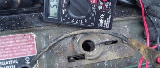
High voltage arrester
Multimeter
If the car engine does not start at all and does not catch, you can evaluate the serviceability of the coil using the parametric method. For this you will need a multimeter. An ordinary coil like the Zhiguli one can be ringed without difficulty. To do this, first set the multimeter’s measurement limit to the resistance measurement mode of 200 Ohms or “diode, continuity” and measure the resistance between the coil terminals + and K. The resistance should be in the range from 0.2 to 1.0 Ohms. Please note that during measurement at this limit a small error may appear, which will slightly increase the multimeter readings. Then switch the multimeter mode to the limit of 20 kOhm and measure the resistance value of the second winding (between terminal K and the copper tip into which the high-voltage wire is inserted). The resistance should be in the range of 1 kilo ohm to 3 kilo ohms (2000 - 3000 ohms).
It is impossible to check a coil with a built-in pulse amplifier using this method, since the lead of the primary winding is not connected to its terminals. A common malfunction of individual devices is breakdown of the limiting resistor. It is located under the rubber extension of the reel structure, which is easily removed. The resistor should be removed and its resistance measured with a multimeter at a limit of 20 kilo-ohms. It should be between 1 and 3 kilo-ohms.
Megaohmmeter
You can also evaluate the insulation resistance if you have a megohmmeter at your disposal. The insulation resistance (between the copper contact into which the high-voltage spark plug wire is inserted and the housing) must be more than 300 megaohms. This measurement is of an evaluative nature. If the resistance is less, the coil is probably faulty, if the resistance is more, it is probably working, it is impossible to judge more precisely.
A simple three-terminal coil can be checked “by weight”, that is, by assembling a simple circuit. The +12V voltage from the battery is connected to the + terminal, a high-voltage wire is inserted into the connector, and a spark plug is connected to the second terminal. The spark plug body is connected to the metal part of the engine. Next, connect a stranded insulated conductor with a cross-section of 2 sq. mm to contact K. Holding the insulation, briefly touch the metal part of the engine with the other stripped end of the wire. A spark should jump where the engine touches and through the spark plug. In electronic coils, the spark from the spark plug is less intense. You cannot experiment with this method for a long time.
Some specialized service stations have self-made inspection stands. Their use requires special methods.